EP0504487A2 - Balance électromécanique avec vibrateur à corde - Google Patents
Balance électromécanique avec vibrateur à corde Download PDFInfo
- Publication number
- EP0504487A2 EP0504487A2 EP91121682A EP91121682A EP0504487A2 EP 0504487 A2 EP0504487 A2 EP 0504487A2 EP 91121682 A EP91121682 A EP 91121682A EP 91121682 A EP91121682 A EP 91121682A EP 0504487 A2 EP0504487 A2 EP 0504487A2
- Authority
- EP
- European Patent Office
- Prior art keywords
- temperature
- quartz
- frequency
- quartz oscillator
- oscillator
- Prior art date
- Legal status (The legal status is an assumption and is not a legal conclusion. Google has not performed a legal analysis and makes no representation as to the accuracy of the status listed.)
- Granted
Links
Images
Classifications
-
- G—PHYSICS
- G01—MEASURING; TESTING
- G01G—WEIGHING
- G01G3/00—Weighing apparatus characterised by the use of elastically-deformable members, e.g. spring balances
- G01G3/12—Weighing apparatus characterised by the use of elastically-deformable members, e.g. spring balances wherein the weighing element is in the form of a solid body stressed by pressure or tension during weighing
- G01G3/16—Weighing apparatus characterised by the use of elastically-deformable members, e.g. spring balances wherein the weighing element is in the form of a solid body stressed by pressure or tension during weighing measuring variations of frequency of oscillations of the body
-
- G—PHYSICS
- G01—MEASURING; TESTING
- G01G—WEIGHING
- G01G3/00—Weighing apparatus characterised by the use of elastically-deformable members, e.g. spring balances
- G01G3/12—Weighing apparatus characterised by the use of elastically-deformable members, e.g. spring balances wherein the weighing element is in the form of a solid body stressed by pressure or tension during weighing
- G01G3/13—Weighing apparatus characterised by the use of elastically-deformable members, e.g. spring balances wherein the weighing element is in the form of a solid body stressed by pressure or tension during weighing having piezoelectric or piezoresistive properties
-
- G—PHYSICS
- G01—MEASURING; TESTING
- G01G—WEIGHING
- G01G3/00—Weighing apparatus characterised by the use of elastically-deformable members, e.g. spring balances
- G01G3/18—Temperature-compensating arrangements
Definitions
- the invention relates to an electromechanical balance with a frequency-giving force sensor and a microprocessor for reshaping the measurement variable, a first quartz oscillator being provided as a clock generator for the microprocessor and as a timer for measuring the vibration frequency of the force sensor, and also with a frequency-giving temperature sensor for measuring the balance temperature.
- a frequency-generating force sensor e.g. a string vibrator may be provided.
- the temperature sensor measures the temperature of the balance, whereby the measured temperature values are evaluated for the arithmetical correction of the measured variable.
- the invention now shows a way to solve the problem mentioned in a simple manner and with less effort.
- the invention consists in that the first quartz oscillator has a temperature-dependent oscillation frequency and serves as a temperature sensor for measuring the balance temperature, that the temperature dependence of the oscillation frequency of this first quartz oscillator is adapted to that of the force sensor, and that a second A quartz oscillator with an oscillation frequency that is at least approximately independent of the temperature is provided, which serves as a timer for measuring the temperature-dependent oscillation frequency of the first quartz oscillator.
- the first quartz oscillator which serves as a clock for the microprocessor and as a timer for measuring the oscillation frequency of the frequency-transmitting force sensor, is a relatively expensive component, primarily due to the tight quality tolerances required with regard to the aforementioned tasks.
- an equally high-quality component for example in the form of a quartz oscillator, is required for the temperature sensor in order to meet the accuracy requirements mentioned.
- the functions of the two quartz oscillators with respect to the temperature measurement are to some extent interchanged, since the clock generator of the microprocessor also functions as a temperature sensor, the second quartz oscillator only serving as a timer, for which cheaper designs are available.
- the first quartz oscillator is also used for direct temperature compensation of the force sensor.
- the latter measure not only has the advantage that the existing high-quality quartz oscillator is better utilized; rather, temperature compensation, which is based on a direct counteraction, is more accurate under the given conditions than the arithmetical correction method. Since the characteristic of the force sensor also represents the most important weighing parameter, the proposed measure is of particular importance. The decisive factor here is the fact that frequency-giving force sensors, for example string vibrators, can be produced with only very little variation in the characteristic curve are, so that a corresponding comparison is unnecessary.
- the exact temperature measurement is used for the mathematical correction of the weighing result based on the other temperature-dependent weighing parameters.
- a second quartz oscillator is only required as a timer in the solution according to the invention.
- a commercially available quartz oscillator designed for watches can be used for this.
- watch crystals are very inexpensive, but still have the accuracy required for the aforementioned purpose and are largely independent of temperature.
- the use of a temperature-independent quartz oscillator as a timer for the frequency-giving temperature sensor has the further advantage that, as is usually the case, two temperature-dependent quartz oscillators with different temperature dependencies of the frequency, but only a single quartz oscillator, are decisive for temperature detection. In this way the interference potential is reduced.
- the print carrying the microprocessor is preferably mounted on the load cell containing the force sensor and arranged together with it in a common housing in order to achieve the most accurate possible detection of the temperature profile in the load cell.
- the temperature as a measured variable can be derived, for example, from the oscillation frequencies of the two quartz oscillators using the temperature functions shown as power series, for example for an initial temperature of 25 ° C.
- the quotient of the two frequency values is only a function of the temperature.
- the temperature information results from equation (3).
- temperature coefficient ⁇ 2 0
- a further advantage results if types are selected for the quartz crystals of the two quartz oscillators, in which the coefficients ( ⁇ ) of the quadratic element of the temperature function shown as a power series are equal to one another. In this case there is a linear dependence of the temperature according to equation (3). An adjustment at a certain temperature value (e.g. 20 °) is sufficient to obtain the absolute temperature as the measured variable. In many cases, however, the adjustment mentioned can even be dispensed with, since the relative accuracy of the temperature measurement is usually sufficient for compensation purposes.
- a certain temperature value e.g. 20 °
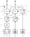
- a string vibrator 1 with a string 4 clamped between two brackets 2 and 3 serves as a frequency-generating force sensor Oscillator 5 is set in natural vibration.
- a signal whose frequency changes with the tension force of the vibrating string 4 acting on the holders 2 and 3, ie with the load on the scale.
- This signal is fed via a pulse shaper 6 to a counter 7 which is controlled by a microprocessor 8.
- the frequency value f 1 corresponding to a certain scale load is determined in the microprocessor 8 in a manner known per se and the weight value GW to be displayed by the scale is calculated taking into account any corrections.
- the first quartz oscillator 9 is also designed as a frequency-giving temperature sensor, ie it is provided with a quartz Q1, whose temperature coefficient ⁇ 1 has a non-zero value.
- the counting pulses taken from the pulse shaper 10 of the quartz oscillator 9 are fed to a further counter 13 in order to determine the temperature value.
- the microprocessor 8 calculates from the counted pulses of the counter 13 in a similar manner to the counter 7, the frequency value f2 and finally the quotient of the two frequency values f1 and f2. The result is a digital temperature value TW that is available for compensation purposes.
- the temperature characteristic curve of the first quartz oscillator 9 is further adapted to that of the string oscillator 1.
- the quartzes Q1 and Q2 used for the two quartz oscillators 9 and 11 are advantageously chosen such that the temperature coefficients ⁇ x have the same value. This results in a linear relationship between the determined temperature value TW and the temperature prevailing at the temperature sensor 9.
Landscapes
- Physics & Mathematics (AREA)
- General Physics & Mathematics (AREA)
- Oscillators With Electromechanical Resonators (AREA)
- Electric Clocks (AREA)
- Indication And Recording Devices For Special Purposes And Tariff Metering Devices (AREA)
Applications Claiming Priority (2)
| Application Number | Priority Date | Filing Date | Title |
|---|---|---|---|
| CH825/91 | 1991-03-19 | ||
| CH825/91A CH684441A5 (de) | 1991-03-19 | 1991-03-19 | Elektromechanische Waage mit Saitenschwinger. |
Publications (3)
| Publication Number | Publication Date |
|---|---|
| EP0504487A2 true EP0504487A2 (fr) | 1992-09-23 |
| EP0504487A3 EP0504487A3 (en) | 1993-04-28 |
| EP0504487B1 EP0504487B1 (fr) | 1995-06-07 |
Family
ID=4196078
Family Applications (1)
| Application Number | Title | Priority Date | Filing Date |
|---|---|---|---|
| EP91121682A Expired - Lifetime EP0504487B1 (fr) | 1991-03-19 | 1991-12-18 | Balance électromécanique avec vibrateur à corde |
Country Status (5)
| Country | Link |
|---|---|
| US (1) | US5232063A (fr) |
| EP (1) | EP0504487B1 (fr) |
| JP (1) | JPH0752591Y2 (fr) |
| CH (1) | CH684441A5 (fr) |
| DE (2) | DE59105670D1 (fr) |
Cited By (1)
| Publication number | Priority date | Publication date | Assignee | Title |
|---|---|---|---|---|
| CN1034441C (zh) * | 1993-08-12 | 1997-04-02 | 武汉大学 | 时间分辨电化学石英晶体微天平 |
Families Citing this family (8)
| Publication number | Priority date | Publication date | Assignee | Title |
|---|---|---|---|---|
| JPH10170669A (ja) * | 1996-12-11 | 1998-06-26 | Hudson Soft Co Ltd | 計測装置及びこれを用いた玩具 |
| US5900592A (en) * | 1997-08-29 | 1999-05-04 | Lockheed Martin Energy Research Corp. | Load sensing system |
| US6080939A (en) * | 1998-06-12 | 2000-06-27 | Rupprecht & Pataschnick Company, Inc. | Mass determination device having counterbalanced normalized temperature coefficients |
| JP2000180250A (ja) * | 1998-10-09 | 2000-06-30 | Ngk Insulators Ltd | 質量センサ及び質量検出方法 |
| WO2001033175A1 (fr) * | 1999-11-01 | 2001-05-10 | The Johns Hopkins University | Unite a commande automatique pour des capteurs a quartz de microbalance |
| GB0229515D0 (en) * | 2002-12-19 | 2003-01-22 | Trw Ltd | Improvements in radar apparatus |
| EP1785703B1 (fr) * | 2005-11-15 | 2011-12-21 | Mettler-Toledo AG | Procédé destiné à la surveillance et/ou la détermination de l'état d'un dispositif de mesure de force et dispositif de mesure de force |
| CN105486334B (zh) * | 2015-12-01 | 2017-11-10 | 常州大学 | 一种关于振弦传感器频率的快速测量装置 |
Family Cites Families (14)
| Publication number | Priority date | Publication date | Assignee | Title |
|---|---|---|---|---|
| JPS52119960A (en) * | 1976-03-31 | 1977-10-07 | Kubota Ltd | Weight transducer using quartz vibrator |
| CH591071A5 (fr) * | 1976-04-01 | 1977-08-31 | Mettler Instrumente Ag | |
| JPS539570A (en) * | 1976-07-14 | 1978-01-28 | Kubota Ltd | Weight transducer |
| JPS5430881A (en) * | 1977-08-12 | 1979-03-07 | Tokyo Electric Co Ltd | Weight measuring aparatus |
| CH638894A5 (de) * | 1979-08-28 | 1983-10-14 | Mettler Instrumente Ag | Elektrische waage. |
| US4382479A (en) * | 1981-05-19 | 1983-05-10 | Setra Systems, Inc. | Weighing system |
| US4464725A (en) * | 1981-05-19 | 1984-08-07 | Setra Systems, Inc. | Temperature compensated measuring system |
| US4513831A (en) * | 1981-05-19 | 1985-04-30 | Setra Systems, Inc. | Weighing system |
| CH654411A5 (de) * | 1981-06-02 | 1986-02-14 | Mettler Instrumente Ag | Elektrische waage. |
| US4418774A (en) * | 1981-12-08 | 1983-12-06 | Franklin Electric Co., Inc. | Weight or force measuring apparatus |
| US4765377A (en) * | 1983-06-06 | 1988-08-23 | Sidney Soloway | Filling and weighing system |
| US4535638A (en) * | 1983-10-03 | 1985-08-20 | Quartztronics, Inc. | Resonator transducer system with temperature compensation |
| US4623030A (en) * | 1985-10-21 | 1986-11-18 | Alcor, Inc. | Piezoelectric ratio weighing device |
| US4838369A (en) * | 1988-09-02 | 1989-06-13 | Crystal Gage Inc. | Load cell having digital output |
-
1991
- 1991-03-19 CH CH825/91A patent/CH684441A5/de not_active IP Right Cessation
- 1991-12-18 EP EP91121682A patent/EP0504487B1/fr not_active Expired - Lifetime
- 1991-12-18 DE DE59105670T patent/DE59105670D1/de not_active Expired - Fee Related
- 1991-12-20 DE DE9115887U patent/DE9115887U1/de not_active Expired - Lifetime
-
1992
- 1992-01-23 US US07/824,405 patent/US5232063A/en not_active Expired - Fee Related
- 1992-03-19 JP JP1992014830U patent/JPH0752591Y2/ja not_active Expired - Lifetime
Cited By (1)
| Publication number | Priority date | Publication date | Assignee | Title |
|---|---|---|---|---|
| CN1034441C (zh) * | 1993-08-12 | 1997-04-02 | 武汉大学 | 时间分辨电化学石英晶体微天平 |
Also Published As
| Publication number | Publication date |
|---|---|
| DE9115887U1 (de) | 1992-02-20 |
| US5232063A (en) | 1993-08-03 |
| JPH04122327U (ja) | 1992-11-02 |
| EP0504487A3 (en) | 1993-04-28 |
| EP0504487B1 (fr) | 1995-06-07 |
| DE59105670D1 (de) | 1995-07-13 |
| CH684441A5 (de) | 1994-09-15 |
| JPH0752591Y2 (ja) | 1995-11-29 |
Similar Documents
| Publication | Publication Date | Title |
|---|---|---|
| DE69422985T2 (de) | Schaltung zur unterdrückung von schwingungen in einem schwingenden laserringkreisel | |
| DE19910415B4 (de) | Verfahren und Vorrichtung zum Abstimmen eines ersten Oszillators mit einem zweiten Oszillator | |
| DE2239998C3 (de) | Waage mit Auswertegerät, Digitalanzeige und einer sich über mehrere Anzeigeeinheiten erstreckenden Null-Grobjustierung | |
| WO2001075399A9 (fr) | Dispositif de mesure de debit massique | |
| DE3706243A1 (de) | Verfahren und einrichtung zur kraftmessung | |
| DE19653592A1 (de) | Von einem Mikroprozessor gesteuerte Sensor-Konditionierungs-Schaltung | |
| DE3119759A1 (de) | Industrielle verfahrensregel- bzw. -messvorrichtung und verfahren zur erzeugung eines signals an einer zentralen steuerstation | |
| EP0504487B1 (fr) | Balance électromécanique avec vibrateur à corde | |
| DE3432987A1 (de) | Vorrichtung zum messen des pegels eines geschmolzenen metalls in der giessform einer stranggiessmaschine | |
| DE3218511C2 (de) | Verfahren und Vorrichtung zum temperaturkompensierten Erfassen einer Kraft | |
| EP0379840B1 (fr) | Manomètre à diapason en quartz | |
| DE102019100863B4 (de) | Temperaturkompensation für Wirbelstromsensoren | |
| DE2824503A1 (de) | Vorrichtung zur messung der schallgeschwindigkeit in werkstuecken | |
| DE2452669A1 (de) | Vorrichtung zur bestimmung der lageaenderung eines gegenstandes | |
| EP0032358A2 (fr) | Oscillateur à compensation de température numérique | |
| DE2239995B2 (de) | Elektronischer Massen- und Kraftmesser | |
| DE3304223C2 (de) | Verfahren und Vorrichtung zur Feststellung der Füllstandshöhe bzw. der An- oder Abwesenheit eines Stoffes in einem Behälter | |
| DE3131455A1 (de) | Magnetostriktiver wegmesser | |
| EP1059516A1 (fr) | Appareil et procédé pour la mesure du niveau de remplissage de récipients | |
| DE1766781B1 (de) | Verfahren zur digitalen quadrierung des quotienten aus einer unbekannten messfrequenz einer eieltrischen spannung und einem konstanten vorgewaehlten wert einer grundfrequenz und vorrich tung zur durchfuehrung des verfahrens | |
| DE2330972C3 (de) | Verfahren und Vorrichtung zum Messen der Dichte eines Meßobjektes durch Frequenzbestimmung | |
| DE2521687C3 (de) | Meßwertwandler zur kapazitiven Füllstandsmessung | |
| DE2534219C3 (de) | Schaltungsanordnung zur digitalen Auswertung der in Form elektrischer Signale vorliegenden Frequenzen von Dehnungsmeßsaiten | |
| DE19648241C2 (de) | Meßverfahren zur Bestimmung von Massen | |
| DE3608384C2 (fr) |
Legal Events
| Date | Code | Title | Description |
|---|---|---|---|
| PUAI | Public reference made under article 153(3) epc to a published international application that has entered the european phase |
Free format text: ORIGINAL CODE: 0009012 |
|
| AK | Designated contracting states |
Kind code of ref document: A2 Designated state(s): DE FR GB |
|
| PUAL | Search report despatched |
Free format text: ORIGINAL CODE: 0009013 |
|
| AK | Designated contracting states |
Kind code of ref document: A3 Designated state(s): DE FR GB |
|
| 17P | Request for examination filed |
Effective date: 19930318 |
|
| 17Q | First examination report despatched |
Effective date: 19940711 |
|
| GRAA | (expected) grant |
Free format text: ORIGINAL CODE: 0009210 |
|
| AK | Designated contracting states |
Kind code of ref document: B1 Designated state(s): DE FR GB |
|
| GBT | Gb: translation of ep patent filed (gb section 77(6)(a)/1977) |
Effective date: 19950612 |
|
| REF | Corresponds to: |
Ref document number: 59105670 Country of ref document: DE Date of ref document: 19950713 |
|
| ET | Fr: translation filed | ||
| PGFP | Annual fee paid to national office [announced via postgrant information from national office to epo] |
Ref country code: DE Payment date: 19951030 Year of fee payment: 7 |
|
| PLBE | No opposition filed within time limit |
Free format text: ORIGINAL CODE: 0009261 |
|
| STAA | Information on the status of an ep patent application or granted ep patent |
Free format text: STATUS: NO OPPOSITION FILED WITHIN TIME LIMIT |
|
| 26N | No opposition filed | ||
| PGFP | Annual fee paid to national office [announced via postgrant information from national office to epo] |
Ref country code: FR Payment date: 19970926 Year of fee payment: 7 |
|
| REG | Reference to a national code |
Ref country code: FR Ref legal event code: CD |
|
| PGFP | Annual fee paid to national office [announced via postgrant information from national office to epo] |
Ref country code: GB Payment date: 19971216 Year of fee payment: 7 |
|
| PG25 | Lapsed in a contracting state [announced via postgrant information from national office to epo] |
Ref country code: GB Free format text: LAPSE BECAUSE OF NON-PAYMENT OF DUE FEES Effective date: 19981218 |
|
| GBPC | Gb: european patent ceased through non-payment of renewal fee |
Effective date: 19981218 |
|
| PG25 | Lapsed in a contracting state [announced via postgrant information from national office to epo] |
Ref country code: FR Free format text: LAPSE BECAUSE OF NON-PAYMENT OF DUE FEES Effective date: 19990831 |
|
| REG | Reference to a national code |
Ref country code: FR Ref legal event code: ST |
|
| PG25 | Lapsed in a contracting state [announced via postgrant information from national office to epo] |
Ref country code: DE Free format text: LAPSE BECAUSE OF NON-PAYMENT OF DUE FEES Effective date: 19991001 |