EP0504240B1 - Entdeckungsvorrichtung - Google Patents
Entdeckungsvorrichtung Download PDFInfo
- Publication number
- EP0504240B1 EP0504240B1 EP91900863A EP91900863A EP0504240B1 EP 0504240 B1 EP0504240 B1 EP 0504240B1 EP 91900863 A EP91900863 A EP 91900863A EP 91900863 A EP91900863 A EP 91900863A EP 0504240 B1 EP0504240 B1 EP 0504240B1
- Authority
- EP
- European Patent Office
- Prior art keywords
- lens
- detection device
- receiver
- transmitter
- microwave
- Prior art date
- Legal status (The legal status is an assumption and is not a legal conclusion. Google has not performed a legal analysis and makes no representation as to the accuracy of the status listed.)
- Expired - Lifetime
Links
- 238000001514 detection method Methods 0.000 title claims abstract description 18
- 230000005855 radiation Effects 0.000 claims abstract description 6
- 239000007788 liquid Substances 0.000 claims description 10
- 239000012530 fluid Substances 0.000 claims description 5
- 238000010586 diagram Methods 0.000 description 2
- 230000000694 effects Effects 0.000 description 2
- 239000000463 material Substances 0.000 description 2
- 230000009977 dual effect Effects 0.000 description 1
- 239000002305 electric material Substances 0.000 description 1
- 239000011521 glass Substances 0.000 description 1
- 239000002480 mineral oil Substances 0.000 description 1
- 235000010446 mineral oil Nutrition 0.000 description 1
- 230000004048 modification Effects 0.000 description 1
- 238000012986 modification Methods 0.000 description 1
- 229920003023 plastic Polymers 0.000 description 1
- 239000004033 plastic Substances 0.000 description 1
- 229920000573 polyethylene Polymers 0.000 description 1
- 239000000725 suspension Substances 0.000 description 1
- 235000015112 vegetable and seed oil Nutrition 0.000 description 1
- 239000008158 vegetable oil Substances 0.000 description 1
Images
Classifications
-
- G—PHYSICS
- G01—MEASURING; TESTING
- G01S—RADIO DIRECTION-FINDING; RADIO NAVIGATION; DETERMINING DISTANCE OR VELOCITY BY USE OF RADIO WAVES; LOCATING OR PRESENCE-DETECTING BY USE OF THE REFLECTION OR RERADIATION OF RADIO WAVES; ANALOGOUS ARRANGEMENTS USING OTHER WAVES
- G01S7/00—Details of systems according to groups G01S13/00, G01S15/00, G01S17/00
- G01S7/02—Details of systems according to groups G01S13/00, G01S15/00, G01S17/00 of systems according to group G01S13/00
-
- G—PHYSICS
- G01—MEASURING; TESTING
- G01S—RADIO DIRECTION-FINDING; RADIO NAVIGATION; DETERMINING DISTANCE OR VELOCITY BY USE OF RADIO WAVES; LOCATING OR PRESENCE-DETECTING BY USE OF THE REFLECTION OR RERADIATION OF RADIO WAVES; ANALOGOUS ARRANGEMENTS USING OTHER WAVES
- G01S13/00—Systems using the reflection or reradiation of radio waves, e.g. radar systems; Analogous systems using reflection or reradiation of waves whose nature or wavelength is irrelevant or unspecified
- G01S13/88—Radar or analogous systems specially adapted for specific applications
- G01S13/93—Radar or analogous systems specially adapted for specific applications for anti-collision purposes
- G01S13/931—Radar or analogous systems specially adapted for specific applications for anti-collision purposes of land vehicles
-
- H—ELECTRICITY
- H01—ELECTRIC ELEMENTS
- H01Q—ANTENNAS, i.e. RADIO AERIALS
- H01Q3/00—Arrangements for changing or varying the orientation or the shape of the directional pattern of the waves radiated from an antenna or antenna system
- H01Q3/12—Arrangements for changing or varying the orientation or the shape of the directional pattern of the waves radiated from an antenna or antenna system using mechanical relative movement between primary active elements and secondary devices of antennas or antenna systems
- H01Q3/14—Arrangements for changing or varying the orientation or the shape of the directional pattern of the waves radiated from an antenna or antenna system using mechanical relative movement between primary active elements and secondary devices of antennas or antenna systems for varying the relative position of primary active element and a refracting or diffracting device
-
- B—PERFORMING OPERATIONS; TRANSPORTING
- B60—VEHICLES IN GENERAL
- B60W—CONJOINT CONTROL OF VEHICLE SUB-UNITS OF DIFFERENT TYPE OR DIFFERENT FUNCTION; CONTROL SYSTEMS SPECIALLY ADAPTED FOR HYBRID VEHICLES; ROAD VEHICLE DRIVE CONTROL SYSTEMS FOR PURPOSES NOT RELATED TO THE CONTROL OF A PARTICULAR SUB-UNIT
- B60W2420/00—Indexing codes relating to the type of sensors based on the principle of their operation
- B60W2420/40—Photo, light or radio wave sensitive means, e.g. infrared sensors
- B60W2420/408—Radar; Laser, e.g. lidar
-
- B—PERFORMING OPERATIONS; TRANSPORTING
- B60—VEHICLES IN GENERAL
- B60Y—INDEXING SCHEME RELATING TO ASPECTS CROSS-CUTTING VEHICLE TECHNOLOGY
- B60Y2400/00—Special features of vehicle units
- B60Y2400/30—Sensors
- B60Y2400/301—Sensors for position or displacement
- B60Y2400/3017—Radars
-
- G—PHYSICS
- G01—MEASURING; TESTING
- G01S—RADIO DIRECTION-FINDING; RADIO NAVIGATION; DETERMINING DISTANCE OR VELOCITY BY USE OF RADIO WAVES; LOCATING OR PRESENCE-DETECTING BY USE OF THE REFLECTION OR RERADIATION OF RADIO WAVES; ANALOGOUS ARRANGEMENTS USING OTHER WAVES
- G01S13/00—Systems using the reflection or reradiation of radio waves, e.g. radar systems; Analogous systems using reflection or reradiation of waves whose nature or wavelength is irrelevant or unspecified
- G01S13/88—Radar or analogous systems specially adapted for specific applications
- G01S13/93—Radar or analogous systems specially adapted for specific applications for anti-collision purposes
- G01S13/931—Radar or analogous systems specially adapted for specific applications for anti-collision purposes of land vehicles
- G01S2013/932—Radar or analogous systems specially adapted for specific applications for anti-collision purposes of land vehicles using own vehicle data, e.g. ground speed, steering wheel direction
-
- G—PHYSICS
- G01—MEASURING; TESTING
- G01S—RADIO DIRECTION-FINDING; RADIO NAVIGATION; DETERMINING DISTANCE OR VELOCITY BY USE OF RADIO WAVES; LOCATING OR PRESENCE-DETECTING BY USE OF THE REFLECTION OR RERADIATION OF RADIO WAVES; ANALOGOUS ARRANGEMENTS USING OTHER WAVES
- G01S13/00—Systems using the reflection or reradiation of radio waves, e.g. radar systems; Analogous systems using reflection or reradiation of waves whose nature or wavelength is irrelevant or unspecified
- G01S13/88—Radar or analogous systems specially adapted for specific applications
- G01S13/93—Radar or analogous systems specially adapted for specific applications for anti-collision purposes
- G01S13/931—Radar or analogous systems specially adapted for specific applications for anti-collision purposes of land vehicles
- G01S2013/9327—Sensor installation details
- G01S2013/93271—Sensor installation details in the front of the vehicles
Definitions
- This invention relates to a detection device which is intended to be mounted on a vehicle and which can provide a signal indicative of an object in front of the vehicle.
- the signal obtained from such a device can be used to modify the operation of one or more of the control systems of the vehicle or it can be used to achieve vehicle braking or it may be used merely to provide a warning to the driver of the vehicle.
- the object of the invention is to provide a microwave device of the kind and for the purpose specified in a simple and convenient form.
- detection device for the purpose specified includes a microwave device constructed so as to provide a fixed beam and includes means for varying the divergence of the beam in accordance with the speed of the vehicle.
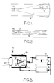
- a vehicle is indicated at 10 and is fitted with a fixed beam microwave range sensor which produces a microwave beam indicated at 11 in Figure 1 and at 12 in Figure 2.
- the vehicle is illustrated as travelling in the centre lane of a motorway in Figure 1 and in the near side lane of a dual carriageway in Figure 2.
- the beam 11 has a wide divergence and it will be seen to cover objects 13 which are not directly in the path of the vehicle whereas in Figure 2 where the beam is narrow, an object 14 which is close to and in the path of the vehicle lies to one side of the beam and is therefore not detected. It is clear therefore that it would be more appropriate to use the narrow beam when travelling on a motorway at a higher speed and the wider beam when travelling at a lower speed in town traffic. It is proposed therefore to vary the divergence of the beam produced by the sensor in accordance with the speed of the vehicle.
- an adjustable beam microwave sensor is shown at 15 and comprises a microwave transmitter/ receiver device 16 mounted on a base 17 which is secured to one end of an outer tube 18 within which is slidable an inner tube 19.
- the inner tube mounts at its end remote from the base, a microwave lens 21 conveniently formed from a plastics, and the two tubes can be moved relative to each other by means of a motor 20 conveniently of the stepper type.
- the motor 20 is mounted on the inner tube 19 and drives a screw threaded shaft which is engaged by a nut mounted on the base 17.
- the motor and the nut are mounted within the interior of the sensor they can be mounted on the outside of the sensor.
- the power of the lens 21 is such that the beam which is produced by the sensor 15 diverges and the extent of the divergence can be varied by altering the distance between the lens 21 and the transmitter/receiver 16.
- the signal provided by the sensor 15 is processed in a processor 22 which is also supplied with a vehicle speed signal and the signal provided by the processor 22 which will indicate the distance of the object from the vehicle, is applied to the vehicle brake and throttle controller 23.
- the controller 23 is also supplied with the vehicle speed signal and can take appropriate action to reduce the speed of the vehicle to avoid collision with the object in the path of the vehicle and moving more slowly than the vehicle.
- the motor 20 is controlled by a control unit 24 which also receives the vehicle speed signal and adjusts the distance between the lens 21 and the transmitter/receiver 16 to provide the appropriate divergence of the beam for the vehicle speed.
- the lateral position of the object apart from its range can be determined by varying the divergence of the beam and if for example the beam is increasing in width as soon as the object is detected, the divergence of the beam will provide an indication of the lateral position of the object. Measuring the rate of change of angle from the straight ahead position provides the trajectory of the object across the beam. This is useful for deciding if action has to be taken when going around bends in the road.
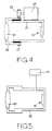
- FIG. 4 An alternative arrangement is seen in Figure 4 in which the inner and outer tubes 25, 26 are provided with an interengaging ball screw thread.
- the outer tube is also provided with a ring gear 27 the teeth of which are engaged by a pinion 28 driven by a stepper motor 29.
- the lens in this case is mounted on the outer tube and the transmitter/receiver 16 on the inner tube.
- the arrangements shown in Figure 3 and 4 vary the divergence of the beam produced by the sensor by varying the distance between the lens 21 and the transmitter/receiver.
- the divergence of the beam produced by the sensor can be varied by maintaining the distance between the lens and the transmitter/receiver constant and varying the dielectric constant of the medium through which the radiation passes between the lens and the transmitter/receiver.
- Figure 5 shows the lens 21 and the transmitter/receiver 16 mounted at opposite ends of a hollow casing 30.
- the pressure of the air or other gas within the casing can be varied. This has the effect of varying the density of the air or other gas and therefore the dielectric constant.
- the interior of the casing is connected to a variable pressure source 31 the pressure of which is controlled in accordance with the vehicle speed by means of the control unit 24.
- the pressure of air or other gas may in fact be below atmospheric pressure and in the case of air, the source of air could be the inlet manifold of the engine driving the vehicle.
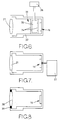
- Figure 6 shows an arrangement in which the casing 32 mounting the lens and the transmitter/receiver 16 contains a cell 33 which contains liquid under pressure.
- the cell is provided with a pair of glass or like windows 34 which between them define a chamber 35 containing the liquid.
- the liquid is derived from a source 36 which may for example be a pump forming part of the vehicle braking system in which case the liquid is brake fluid.
- the fluid may also be taken from the vehicle power steering system or the suspension system. Again the pressure of the liquid in the chamber 35 is controlled in accordance with vehicle speed.
- Figure 7 shows the lens 21 and the transmitter/receiver 16 in a fixed relationship and in order to adjust the divergence of the beam the operating frequency of the transmitter/receiver is varied using a suitable control 37.
- a further way of varying the divergence of the beam is to adjust the focal length of the lens.
- the lens 38 and the transmitter/receiver 16 are mounted in fixed relationship with each other.
- a ring 39 formed from piezo-electric material or a plurality of cells formed from the same material spaced about the lens.
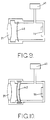
- a flexible diaphragm 40 there is introduced between the transmitter/receiver 16 and the lens 21 a flexible diaphragm 40.
- the diaphragm may be formed from polythene and is transparent to the radiation beam and interposed between the diaphragm and the lens 21 is a liquid such as vegetable oil based brake fluid or mineral oil.
- the space between the diaphragm and the transmitter/receiver is connected to a source 41 of air under pressure.
- the pressure of air can be varied to change the curvature of the diaphragm.
- the volume of liquid must be able to change to accommodate the change in shape of the diaphragm and this can be achieved by allowing some air or other gas to remain in the space or by providing an expansion cylinder.
- Figure 10 there is interposed between the transmitter/receiver 16 and the lens 21 a fluid filled chamber 42 the walls of which are again transparent to the beam and are flexible.
- the pressure of air between the chamber 42 and the transmitter/receiver 16 can be varied to cause flexure of the walls of the chamber.
- the chamber forms as does the diaphragm of Figure 9, a supplementary lens the focus of which can be varied to vary the angle of the divergence of the beam.
- the divergence of the beam may also be adjusted by setting up a standing wave in the lens normal to the microwave waves and adjusting the frequency of the standing wave, the beam width of the microwave signal can be adjusted through interference with the standing wave.
- the standing wave can be generated in the lens using a transducer in the form of a Braggs cell.
- the standing wave also has the effect of changing the effective density of the material forming the lens.
Landscapes
- Engineering & Computer Science (AREA)
- Radar, Positioning & Navigation (AREA)
- Remote Sensing (AREA)
- Physics & Mathematics (AREA)
- Computer Networks & Wireless Communication (AREA)
- General Physics & Mathematics (AREA)
- Electromagnetism (AREA)
- Radar Systems Or Details Thereof (AREA)
- Manufacture Or Reproduction Of Printing Formes (AREA)
- Printing Plates And Materials Therefor (AREA)
- Optical Radar Systems And Details Thereof (AREA)
Claims (14)
- Erkennungseinrichtung zum Anbringen an einem Fahrzeug mit einer Mikrowelleneinrichtung, wobei die Erkennungseinrichtung ein Signal bereitstellt, welches kennzeichnend für ein Objekt vor dem Fahrzeug ist, dadurch gekennzeichnet, daß
die Mikrowelleneinrichtung einen Feststrahl bereitstellt, wobei die Erkennungseinrichtung weiter ein Mittel zum Variieren der Divergenz des Strahles entsprechend der Fahrzeuggeschwindigkeit aufweist. - Erkennungseinrichtung nach Anspruch 1, gekennzeichnet durch eine Linse, die relativ zu der Mikrowelleneinrichtung derart angeordnet ist, daß die durch die Mikrowelleneinrichtung ausgesandte Strahlung durch die Linse hindurch gelassen wird.
- Erkennungseinrichtung nach Anspruch 2,
dadurch gekennzeichnet, daß
die Mikrowelleneinrichtung ein Sender/Empfänger ist, wobei die Linse auch die von einem Objekt reflektierte Strahlung hindurch läßt. - Erkennungseinrichtung nach Anspruch 2,
dadurch gekennzeichnet, daß
das Mittel den Abstand zwischen der Linse und der Mikrowelleneinrichtung einstellt. - Erkennungseinrichtung nach Anspruch 4,
dadurch gekennzeichnet, daß
das Mittel einen Schrittmotor aufweist. - Erkennungseinrichtung nach Ansprüch 2,
dadurch gekennzeichnet, daß
das Mittel die Dielektrizitätskonstante des Mediums, das zwischen der Linse und der Mikrowelleneinrichtung angeordnet ist, einstellt. - Erkennungseinrichtung nach Anspruch 6,
dadurch gekennzeichnet, daß
das Medium Luft oder ein anderes Gas ist und ein Mittel vorgesehen ist zum Ändern des Druckes der Luft oder des anderen Gases. - Erkennungseinrichtung nach Anspruch 6,
dadurch gekennzeichnet, daß
das Medium eine Flüssigkeit ist, die in einer Zelle enthalten ist, die sich zwischen der Linse und der Mikrowelleneinrichtung befindet, wobei ein Mittel zum Ändern des Druckes der Flüssigkeit vorgesehen ist. - Einrichtung nach Anspruch 2,
dadurch gekennzeichnet, daß
das Mittel die Brennweite der Linse einstellt. - Erkennungseinrichtung nach Anspruch 9,
dadurch gekennzeichnet, daß
das Mittel ein piezoelektrisches Element aufweist, das zum Verändern der Form der Linse betreibbar ist. - Erkennungseinrichtung nach Anspruch 2,
dadurch gekennzeichnet, daß
das Mittel eine stehende Welle innerhalb der Linse erzeugt, wobei die Frequenz der stehenden Welle einstellbar ist. - Erkennungseinrichtung nach Anspruch 2, gekennzeichnet durch eine Linse mit variablem Brennpunkt, welche zwischen die erste erwähnte Linse und den Sender/Empfänger eingebracht ist.
- Erkennungseinrichtung nach Anspruch 12,
dadurch gekennzeichnet, daß
die weitere Linse eine flüssigkeitsgefüllte Kammer mit flexiblen Seitenwänden und ein Mittel zum Variieren des Druckes, der gegen die Wand der Kammer angelegt wird zum Bewirken einer Verbiegung der Seitenwände aufweist. - Erkennungseinrichtung nach Anspruch 12,
dadurch gekennzeichnet, daß
die weitere Linse ein flexibles Diaphragma, welches zwischen den Sender/Empfänger und die erste erwähnte Linse eingebracht ist, wobei der Raum, der zwischen dem Diaphragma und der Linse definiert ist, durch Flüssigkeit besetzt ist und ein Mittel, das vorgesehen ist zum Variieren des Druckes, der an die Fläche des Diaphragmas angelegt wird, die zu dem Sender/Empfänger zeigt, zum Variieren der Krümmung des Diaphragmas, aufweist.
Applications Claiming Priority (3)
| Application Number | Priority Date | Filing Date | Title |
|---|---|---|---|
| GB8927905 | 1989-12-09 | ||
| GB898927905A GB8927905D0 (en) | 1989-12-09 | 1989-12-09 | Detection device |
| PCT/GB1990/001913 WO1991009323A2 (en) | 1989-12-09 | 1990-12-07 | Detection device |
Publications (2)
| Publication Number | Publication Date |
|---|---|
| EP0504240A1 EP0504240A1 (de) | 1992-09-23 |
| EP0504240B1 true EP0504240B1 (de) | 1995-02-15 |
Family
ID=10667727
Family Applications (1)
| Application Number | Title | Priority Date | Filing Date |
|---|---|---|---|
| EP91900863A Expired - Lifetime EP0504240B1 (de) | 1989-12-09 | 1990-12-07 | Entdeckungsvorrichtung |
Country Status (7)
| Country | Link |
|---|---|
| EP (1) | EP0504240B1 (de) |
| JP (1) | JPH05502296A (de) |
| KR (1) | KR920704154A (de) |
| BR (1) | BR9007900A (de) |
| DE (1) | DE69017043T2 (de) |
| GB (1) | GB8927905D0 (de) |
| WO (1) | WO1991009323A2 (de) |
Families Citing this family (16)
| Publication number | Priority date | Publication date | Assignee | Title |
|---|---|---|---|---|
| JP3278871B2 (ja) * | 1991-09-13 | 2002-04-30 | 株式会社デンソー | アンテナ装置 |
| DE4326529A1 (de) * | 1993-08-06 | 1995-02-09 | Bayerische Motoren Werke Ag | Verfahren zum Vermeiden von Kollisionen von Kraftfahrzeugen |
| JP3163981B2 (ja) * | 1996-07-01 | 2001-05-08 | 株式会社村田製作所 | 送受信装置 |
| DE19642810C1 (de) * | 1996-10-17 | 1998-04-02 | Bosch Gmbh Robert | Radarsystem, insbesondere Kraftfahrzeug-Radarsystem |
| JPH10145129A (ja) * | 1996-11-01 | 1998-05-29 | Honda Motor Co Ltd | アンテナ装置 |
| JPH10284930A (ja) * | 1997-04-04 | 1998-10-23 | Murata Mfg Co Ltd | アンテナ装置および送受信装置 |
| DE19737292C1 (de) * | 1997-08-27 | 1999-06-10 | Bosch Gmbh Robert | Antennenlinse und Kraftfahrzeug-Radarsystem |
| DE19961774A1 (de) * | 1999-12-21 | 2001-07-12 | Bosch Gmbh Robert | Vorrichtung zum Einstellen eines Richtstrahlsystems |
| DE10059891A1 (de) * | 2000-12-01 | 2002-06-13 | Continental Teves Ag & Co Ohg | Kraftfahrzeugabstandssensor |
| JP3473576B2 (ja) * | 2000-12-05 | 2003-12-08 | 株式会社村田製作所 | アンテナ装置および送受信装置 |
| JP2002246832A (ja) * | 2001-02-15 | 2002-08-30 | Matsushita Electric Ind Co Ltd | 通信装置 |
| DE10113323C2 (de) | 2001-03-20 | 2003-04-03 | Bosch Gmbh Robert | Radarsensorplattform |
| US7724180B2 (en) * | 2007-05-04 | 2010-05-25 | Toyota Motor Corporation | Radar system with an active lens for adjustable field of view |
| JP2010528378A (ja) * | 2007-05-25 | 2010-08-19 | エックスバグ・プロプライエタリー・リミテッド | 車両制御方法およびシステム |
| DE102007027975A1 (de) * | 2007-06-19 | 2008-12-24 | Robert Bosch Gmbh | Sensorvorrichtung für ein Kraftfahrzeug |
| JP2014155098A (ja) * | 2013-02-12 | 2014-08-25 | Nitto Denko Corp | アンテナモジュールおよびその製造方法 |
Family Cites Families (9)
| Publication number | Priority date | Publication date | Assignee | Title |
|---|---|---|---|---|
| BE354930A (de) * | 1933-08-31 | |||
| US2716746A (en) * | 1950-10-31 | 1955-08-30 | Rca Corp | Focusing of radar beams for a tracking radar |
| US3448822A (en) * | 1966-06-23 | 1969-06-10 | Micro Electronics Intern Inc | Vehicle anti-collision automatic control-system |
| US3749197A (en) * | 1971-05-12 | 1973-07-31 | B Deutsch | Obstacle detection system |
| US4062018A (en) * | 1973-12-21 | 1977-12-06 | Kokusai Denshin Denwa Kabushiki Kaisha | Scanning antenna with moveable beam waveguide feed and defocusing adjustment |
| DE2623643C2 (de) * | 1976-05-26 | 1986-11-20 | Daimler-Benz Ag, 7000 Stuttgart | Verfahren zum selbsttätigen Regeln des Sicherheitsabstandes eines Fahrzeuges zu vorausfahrenden Fahrzeugen und Vorrichtung zur Durchführung dieses Verfahrens |
| US4791427A (en) * | 1985-11-22 | 1988-12-13 | United Technologies Corporation | Multimode, multispectral antenna |
| DE3630700A1 (de) * | 1986-09-09 | 1988-03-17 | Siemens Ag | Optische linse |
| US4833469A (en) * | 1987-08-03 | 1989-05-23 | David Constant V | Obstacle proximity detector for moving vehicles and method for use thereof |
-
1989
- 1989-12-09 GB GB898927905A patent/GB8927905D0/en active Pending
-
1990
- 1990-12-07 EP EP91900863A patent/EP0504240B1/de not_active Expired - Lifetime
- 1990-12-07 BR BR909007900A patent/BR9007900A/pt not_active Application Discontinuation
- 1990-12-07 JP JP3501316A patent/JPH05502296A/ja active Pending
- 1990-12-07 KR KR1019920701368A patent/KR920704154A/ko not_active Abandoned
- 1990-12-07 DE DE69017043T patent/DE69017043T2/de not_active Expired - Lifetime
- 1990-12-07 WO PCT/GB1990/001913 patent/WO1991009323A2/en not_active Ceased
Also Published As
| Publication number | Publication date |
|---|---|
| WO1991009323A2 (en) | 1991-06-27 |
| EP0504240A1 (de) | 1992-09-23 |
| JPH05502296A (ja) | 1993-04-22 |
| BR9007900A (pt) | 1992-08-25 |
| WO1991009323A3 (en) | 1991-09-05 |
| DE69017043T2 (de) | 1995-09-21 |
| KR920704154A (ko) | 1992-12-19 |
| DE69017043D1 (de) | 1995-03-23 |
| GB8927905D0 (en) | 1990-02-14 |
Similar Documents
| Publication | Publication Date | Title |
|---|---|---|
| WO1991009323A2 (en) | Detection device | |
| US6073491A (en) | Method and arrangement for making contactless distance and pressure measurements within an air spring | |
| US5337864A (en) | Suspension system with improved resonance damping and a method for regulating the suspension system | |
| US8692706B2 (en) | Sensor device for measuring the compression travel and/or the compression rate of wheels and/or axles of vehicles | |
| US5936161A (en) | Arrangement for making contactless distance measurements | |
| EP0710389B1 (de) | Akoustische sende- und empfangseinheit | |
| JP2977898B2 (ja) | ソナー位置センサを有するショックアブソーバ | |
| CN1113009A (zh) | 使用聚合压电膜的探物传感器 | |
| US20070151364A1 (en) | Apparatus for ascertaining and/or monitoring volume-or mass-flow of a medium | |
| KR100443119B1 (ko) | 간격 측정 장치 | |
| JP2004340911A (ja) | 車両用液面検出装置 | |
| US4945768A (en) | Pressure sensor | |
| JP4277761B2 (ja) | 液面検出装置 | |
| US4441173A (en) | Very low frequency hydrophone calibration | |
| JP2004294073A (ja) | 車両用液面検出装置 | |
| KR970001153A (ko) | 간섭 발진방식의 공진주파수 조정방법 | |
| JP3908189B2 (ja) | 車両用液面検出装置 | |
| JPH06308225A (ja) | 車載用レーダ装置 | |
| US7148467B2 (en) | Object detecting apparatus having case breakage detecting function | |
| JP4120554B2 (ja) | 車両用液面検出装置 | |
| JP3510480B2 (ja) | 音響レンズ付き指向性送波器 | |
| JP2005117569A (ja) | 超音波センサ | |
| US2987699A (en) | Homing-torpedo reverberation-attenuating transducer apparatus | |
| JPH07282399A (ja) | 車間距離測定方法 | |
| GB2153124A (en) | Apparatus for sensing the distance between two bodies, one of which is moving relative to the other |
Legal Events
| Date | Code | Title | Description |
|---|---|---|---|
| PUAI | Public reference made under article 153(3) epc to a published international application that has entered the european phase |
Free format text: ORIGINAL CODE: 0009012 |
|
| 17P | Request for examination filed |
Effective date: 19920413 |
|
| AK | Designated contracting states |
Kind code of ref document: A1 Designated state(s): DE FR GB IT |
|
| 17Q | First examination report despatched |
Effective date: 19940419 |
|
| GRAA | (expected) grant |
Free format text: ORIGINAL CODE: 0009210 |
|
| AK | Designated contracting states |
Kind code of ref document: B1 Designated state(s): DE FR GB IT |
|
| ITF | It: translation for a ep patent filed | ||
| REF | Corresponds to: |
Ref document number: 69017043 Country of ref document: DE Date of ref document: 19950323 |
|
| ET | Fr: translation filed | ||
| PLBE | No opposition filed within time limit |
Free format text: ORIGINAL CODE: 0009261 |
|
| STAA | Information on the status of an ep patent application or granted ep patent |
Free format text: STATUS: NO OPPOSITION FILED WITHIN TIME LIMIT |
|
| 26N | No opposition filed | ||
| REG | Reference to a national code |
Ref country code: GB Ref legal event code: IF02 |
|
| REG | Reference to a national code |
Ref country code: GB Ref legal event code: 732E |
|
| PGFP | Annual fee paid to national office [announced via postgrant information from national office to epo] |
Ref country code: GB Payment date: 20061106 Year of fee payment: 17 |
|
| PGFP | Annual fee paid to national office [announced via postgrant information from national office to epo] |
Ref country code: FR Payment date: 20061201 Year of fee payment: 17 |
|
| PGFP | Annual fee paid to national office [announced via postgrant information from national office to epo] |
Ref country code: IT Payment date: 20061231 Year of fee payment: 17 |
|
| REG | Reference to a national code |
Ref country code: GB Ref legal event code: 732E |
|
| GBPC | Gb: european patent ceased through non-payment of renewal fee |
Effective date: 20071207 |
|
| REG | Reference to a national code |
Ref country code: FR Ref legal event code: ST Effective date: 20081020 |
|
| PG25 | Lapsed in a contracting state [announced via postgrant information from national office to epo] |
Ref country code: GB Free format text: LAPSE BECAUSE OF NON-PAYMENT OF DUE FEES Effective date: 20071207 |
|
| PG25 | Lapsed in a contracting state [announced via postgrant information from national office to epo] |
Ref country code: FR Free format text: LAPSE BECAUSE OF NON-PAYMENT OF DUE FEES Effective date: 20071231 |
|
| PG25 | Lapsed in a contracting state [announced via postgrant information from national office to epo] |
Ref country code: IT Free format text: LAPSE BECAUSE OF NON-PAYMENT OF DUE FEES Effective date: 20071207 |
|
| PGFP | Annual fee paid to national office [announced via postgrant information from national office to epo] |
Ref country code: DE Payment date: 20091203 Year of fee payment: 20 |
|
| PG25 | Lapsed in a contracting state [announced via postgrant information from national office to epo] |
Ref country code: DE Free format text: LAPSE BECAUSE OF EXPIRATION OF PROTECTION Effective date: 20101207 |