EP0503762A2 - Pantographische Halterung für einen Transducer - Google Patents
Pantographische Halterung für einen Transducer Download PDFInfo
- Publication number
- EP0503762A2 EP0503762A2 EP92301019A EP92301019A EP0503762A2 EP 0503762 A2 EP0503762 A2 EP 0503762A2 EP 92301019 A EP92301019 A EP 92301019A EP 92301019 A EP92301019 A EP 92301019A EP 0503762 A2 EP0503762 A2 EP 0503762A2
- Authority
- EP
- European Patent Office
- Prior art keywords
- leaf
- leaves
- mount
- fixed body
- stiffness
- Prior art date
- Legal status (The legal status is an assumption and is not a legal conclusion. Google has not performed a legal analysis and makes no representation as to the accuracy of the status listed.)
- Granted
Links
Images


Classifications
-
- G—PHYSICS
- G11—INFORMATION STORAGE
- G11B—INFORMATION STORAGE BASED ON RELATIVE MOVEMENT BETWEEN RECORD CARRIER AND TRANSDUCER
- G11B5/00—Recording by magnetisation or demagnetisation of a record carrier; Reproducing by magnetic means; Record carriers therefor
- G11B5/48—Disposition or mounting of heads or head supports relative to record carriers ; arrangements of heads, e.g. for scanning the record carrier to increase the relative speed
- G11B5/58—Disposition or mounting of heads or head supports relative to record carriers ; arrangements of heads, e.g. for scanning the record carrier to increase the relative speed with provision for moving the head for the purpose of maintaining alignment of the head relative to the record carrier during transducing operation, e.g. to compensate for surface irregularities of the latter or for track following
- G11B5/584—Disposition or mounting of heads or head supports relative to record carriers ; arrangements of heads, e.g. for scanning the record carrier to increase the relative speed with provision for moving the head for the purpose of maintaining alignment of the head relative to the record carrier during transducing operation, e.g. to compensate for surface irregularities of the latter or for track following for track following on tapes
- G11B5/588—Disposition or mounting of heads or head supports relative to record carriers ; arrangements of heads, e.g. for scanning the record carrier to increase the relative speed with provision for moving the head for the purpose of maintaining alignment of the head relative to the record carrier during transducing operation, e.g. to compensate for surface irregularities of the latter or for track following for track following on tapes by controlling the position of the rotating heads
-
- G—PHYSICS
- G11—INFORMATION STORAGE
- G11B—INFORMATION STORAGE BASED ON RELATIVE MOVEMENT BETWEEN RECORD CARRIER AND TRANSDUCER
- G11B5/00—Recording by magnetisation or demagnetisation of a record carrier; Reproducing by magnetic means; Record carriers therefor
- G11B5/02—Recording, reproducing, or erasing methods; Read, write or erase circuits therefor
Definitions
- This invention relates to signal transducers, also known as heads in the art, such as may be used in storing information in a storage medium such as magnetic tape, and in retrieving the information stored therein and, more particularly, this invention relates to an assembly for holding, supporting and varying the position of a signal transducer.
- helical-scan magnetic tape transports employ one or more mounting assemblies for supporting and adjustably positioning a magnetic transducing head in a rotating drum.
- One such assembly is disclosed in US Patent No.4,212,043 which was filed 1 November 1978 and which issued 8 July 1980 and which is incorporated herein by reference.
- adjustable mounts are secured to the interior of the rotating drum and extend radially toward the periphery of the drum with the head protruding through an opening in the drum to scan the recorded tracks on a magnetic tape curved around the periphery of the drum in a helical path.
- This adjustable mount permits the head to move laterally with respect to the length direction of a recorded track.
- Each adjustable mount also known as a flexural pantographic mechanism in the art, includes a pair of parallel bending or pivoting leaf members anchored at one set of ends to a fixed body.
- the leaf members extend as cantilevered beams with the transducing head assembly mounted near the opposite set of ends in a manner so that the head assembly can operate as a moveable body.
- Each leaf assembly is suitably constructed so that, when a control voltage is applied such as by a tape transport head positioning servo system to a voice coil assembly, the leaf members deflect accordingly, thereby displacing the transducing head supported thereon.
- the extent and direction of the deflection of the head is proportional to and a function of the amplitude and polarity of the control voltage applied to the voice coil.
- the head When used in combination with a servo system feedback circuit, the head may be positioned in an optimum location for following a tape track, which has been recorded on the magnetic tape medium.
- Such a head positioning arrangement has some disadvantages.
- the inherent flexibility of usually long, thin head positioning leaf members sets up undesirable resonances in the leaf members under rapid and repetitive flexure loadings. Such resonances also result in undesirable deflections under repeated flexures of the leaf members.
- the occurrence of such conditions in the leaf members under the desired loading sequence can severely impair the ability of a head mounted on a leaf member to accurately follow a magnetic tape track.
- Such undesirable conditions can be substantially aggravated unless the frequencies of higher mode vibrations, also called oscillations in the art, are raised substantially higher than the frequency bandwidth of a suitable closed loop servo system of which the mounting assembly is a part.
- the primary, or first, mode stiffness K of a leaf member is defined as the ratio F/D, where F is a component of a force that is perpendicular to the plane of a leaf member and D is the deflection of the leaf member. Since the power utilized in producing the force, and hence the deflection, increases with increasing primary mode stiffness, it is desirable to design the leaves in such a manner so as to minimize the primary mode stiffness. At the same time, it is desirable to raise the frequencies of the vibrations of the higher order modes so as to attenuate the undesirable excitation from the higher frequency oscillations mentioned above.
- the higher order mode frequencies can be raised by increasing the higher order mode stiffness of the leaf members to values beyond the designed bandwidth of the dosed loop servo system, i.e., the higher mode frequencies can be increased so that any undesirable excitation that they may put upon the servo system is so significantly attenuated that the servo system, for all practical purposes, is not subjected to those undesirable effects of the higher order mode vibrations.
- U.S. Patent 4,212,043 discloses a solution to this problem wherein the leaf thickness is not uniform. Instead, stiffening members are attached to the central portion of both sides of a much thinner leaf to form laminated leaf composites. This solution, however, can be costly since more parts and additional assembly steps are usually required. Moreover, the stresses on the end portions of the leaves which do not contact the stiffening members are so highly concentrated that it often necessitates that a costly, very thin, high yield strength material be used for this composite laminate construction to maintain the same low primary mode stiffness as with an equivalent constant leaf thickness pantograph mechanism.
- the mount exhibits an acceptably low primary mode stiffness and a suitably increased higher order mode stiffness and is adapted for use in a magnetic tape transport employing a closed loop servo system having a specified frequency bandwidth.
- the mount includes a fixed body and a moveable body such as a magnetic transducing head assembly as well as first and second parallel spaced apart elongated flexible yet similar flexural pantographic leaves. Each flexural pantographic leaf has two opposite ends, two opposite edges and a defined, and preferably uniform, thickness.
- the leaves of the mount include first and second leaf edge extensions, which act as side stiffeners, each edge stiffener being integral with one of the opposite edges of the corresponding leaf.
- Each leaf side stiffener is positioned and constructed so as to leave the leaf thickness unaltered and to leave the value of the primary mode stiffness substantially unaltered, while at the same time raising the stiffness of the higher mode vibrations to values at which their corresponding natural mode frequencies are substantially higher than the specified frequency bandwidth.
- the side stiffeners which minimally increase the primary mode stiffness and which substantially increase the higher order mode stiffnesses of the mount, do not add extra parts to the flexural pantographic leaves themselves.
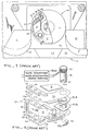
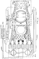
- a broad band magnetic tape transport 11 comprising a tape deck 11a on which is mounted triangular framework 11b, which in turn supports a mounting block 11c for a helical tape scanning drum assembly 11d.
- the drum assembly 11d comprises a rotating central drum portion 12 and stationary upper and lower portions 14 and 15, which are solidly mounted to extend from mounting block 11c, and which constitute mandrels for guiding and forming the tape 17 in a helical path around the rotating drum 12.
- the rotating central drum 12 is fixed to a shaft 16, which constitutes the drive shaft of a motor 18 that is mounted on the lower drum portion 15.
- a pair of diametrically opposed magnetic transducing head assemblies 20 are provided for the rotating drum 12, and the tape is guided by means of a pair of tilted guides 21 in a 180 degree "omega" wrap around the scanning drum assembly 11d and between a pair of tape storage and tensioning reels (not shown) of conventional type.
- the word omega is used to described the wrap because the wrap looks similar to the Greek letter omega, i.e. to the Greek letter ⁇ .
- the head assemblies are each mounted for either rapid or gradual positioning motion in either of the two opposite directions substantially normal to the plane of the rotating drum 12, as by means of springy and flexibly hinged parallel-linkage mounting assemblies 22, also shown in FIG. 3 and also referred herein to as a mounting structure and as a mount.
- An electrical voice coil 23 is mounted on each mounting assembly 22 and is coupled to a tape transport head positioning servo system 300 for providing reversible currents of varying magnitudes causing the coil to act as the movable element of a linear motor for producing the above-described positioning motion of the head assembly 20.
- the stator element of the linear motor is constituted by a permanent magnet member 24, which is fixed to the upper portion 12a of rotating drum 12.
- the portion 12a is made of carbon steel, and also supports a tubular outer pole piece, which circumvallates coil 23, and an inner pole piece that is itself circumvallated by the coil 23.
- a positional sensing coil (not shown) is mounted on each parallel-linkage mounting assembly 22, circumvallating a fixed ferrite element so as to provide a position sensing signal to the servo system 300.
- the fixed ferrite element (not shown) is mounted in an aluminum bushing within a shielding cup (not shown), which can be made, for example, of magnetic shielding conetic material; and the cup in turn is mounted on an aluminum extension member (not shown), attached to the end of the inner pole piece.
- the circuits needed to produce the linear motor driving current and the position sensing signal receiving means form no part of the present invention, and may be conventional as in the prior art (see, for example, U .S. Patent No. 4,485,414).
- the head assemblies 22, which are to be reciprocatingly moved each comprise, in this illustrative discussion, up to ten or more individual magnetic pole-and-gap structures 26, each electrically isolated from the others and constituting a separate magnetic transducing head structure.
- the mass of the "head stack" 20 is far greater than that of the individual transducer structures that have in the prior art been reciprocated satisfactorily, as by means of single leaf structures consisting of bending piezoelectric "bimorph" assembled or pivoting magnetically driven elements. It is also true that the lateral displacements required in a multiple-head stack are greater, and lie generally outside the displacement capability, of the prior art bimorph leaf.
- the head stack 20 actually weighs only a few hundreths of an ounce (or, about 1 gm.) but under the centrifugal forces that are generated during operation, the equivalent mass of such a head stack can be in the neighborhood of 22 pounds (or, about 9.97 kg.). If such a mass were to be fixed at the tip of a bimorph leaf of the prior art, which bends in a characteristic circular arc (see, for example, U. S. Patent No. 4,151,569), or in an S-shape consisting of two oppositely curving circular arcs (see, for example, U .S. Patent No.
- a first bad result relates to the degree of straightening that would vary for different rotational speeds of the drum, with consequent variations in the contact of head and tape, or of the penetration of the head into the tape.
- a second bad result would be a sharp increase in the degree of curvature at the point where the bimorph leaf is anchored to the drum structure, resulting in abnormal concentration of stress and rapid failure or short life for the bimorph leaf structure.
- the leaf is constructed as an already-straight member of great rigidity and stiffness, except at flexure points adjacent the base and adjacent the magnetic head stack, where the structure operates as a springy flexure hinge and is made of materials that are adapted to withstand stress and fatigue, so as to provide cohesive strength and long life for the combination.
- two leaves are used, in parallel-motion linkage arrangement, in order to keep the massive head stack correctly oriented during operation.
- the two leaves of springy and flexibly hinged parallel-linkage mounting assembly 22 are formed as two members 30 of thin "Elgiloy" spring material reinforced by their respective aluminum stiffening members 31, and anchored at the base in a clamping structure consisting of a central spacing block 32 and two sandwiching clamping plates 33, all of aluminum. All of the named parts may be assembled and permanently attached and, where needful, by means of epoxy adhesive.
- the mounting assembly 22 is clamped together and to the drum 12 by means of three stainless steel bolts 34 passing through conforming holes 36 in the elements and threaded into the structure of the rotating drum main (stainless steel) disc 37 (see also FIG. 2).
- the holes 36 are larger in diameter than the bolts 34, so that the bolts function only as clamping bolts; and the base structure is accurately positioned in the plane of disc 37 as by means of orthogonally related gauge surfaces 38 and 39 formed on the spacing block 32, which surfaces are arranged to engage mating gauge surfaces 41 and 42, respectively, formed on the inner side of a peripheral flange 43 of the disc 37.
- the spring members 30 also have edge surfaces 38a dimensioned to lie in the same plane as surface 38 and to act as positioning edges for the assembly.
- the surface 41 is formed parallel to the radial plane of the head stack 20 that passes through the drum axis, so that as the block 32 slides or is slidably adjusted along this surface, the head stack 20 is moved radially in or out through a window opening 44, so as to be adjusted for correct radial position with respect to the outer peripheral surface 46 of the drum and to the tape 17.
- This radial position can be accurately achieved and maintained by means of shims (not shown) placed between the gauge surface 39 of block 32 and gauge surface 42 of the disc 37 prior to tightening the clamping bolts.
- the middle bolt 34 can be formed as a conically tapered screw 34' (FIG.
- a brass locking nut 48 can be provided to lock the tapered screw 34' in its adjusted position.
- the head stack 20 of springy and flexibly hinged parallel-linkage mounting structure 22 is mounted between a pair of brackets 51 extending from base housing 52, which is formed as a hollow aluminum box.
- the housing 52 is affixed to a linear-motor support element 53 consisting of a hollow aluminum tube formed with integral peripheral stiffening flanges 54 adjacent the ends; the ends of spring leaves 30 are affixed to the upper and lower faces of the respective flanges, and the housing 52 is affixed between the flanges.
- a hollow tubular magnesium coil form 56 which is affixed within the tubular portion of support element 53.
- the coil form 56 has an integral hollowed-out spider 57 at the lower end, defining a central tubular opening into which is affixed a Nylon or Derin (Trademarks of DuPont) plastic tubular form for the aforementioned sensing coil (not shown).
- a Nylon or Derin Trademarks of DuPont
- a fixed body 410 which can be embodied in the prior art clamping structure of FIG. 3 including a central spacing block 32, sandwiching clamping plates 33, and bolts 34, is spaced apart by leaves 414 and 416 from a movable body 412, also called a moveable head assembly or simply a head assembly or a moveable assembly, which can be embodied in the prior art head stack 20, which is mounted between a pair of brackets 51 extending from base housing 52, which is affixed to a linear-motor support element 53 consisting of a hollow aluminum tube with integral peripheral stiffening flanges 54 adjacent the ends of two leaves.
- First and second parallel and similar leaves 414 and 416 of similar material and uniform lengths and widths which can be embodied in the two prior art leaves formed as members 30 of thin "Elgiloy" spring material reinforced by the aluminum stiffening members 31, extend between fixed body 410 and moveable assembly 412.
- One set of ends of the leaves is embedded in, or connected to, body 410, for example, by means o the aforedescribed clamping structure while an opposite set of ends is embedded in, or connected to, moveable assembly 412, for example, by means of the aforedescribed head stack, brackets, base housing, support elements, flanges, and hollow tube structure.
- the embedded ends of the leaves remain locked, or affixed, or attached to, or fastened in position while the main body of the leaves are effectively hinged at the embedded ends.
- the moveable body 412 here embodied as the head assembly
- the assembly 412 is deflected a distance D in the direction of the force.
- the leaves 414 and 416 have a primary stiffness K equal to the ratio F/D and exhibit a characteristic "S" shape, which is representative of a primary mode shape 417.
- the leaves 414 and 416 have a secondary mode shape 418 with a central upward bulge, which is substantially in the direction of the force F.
- a secondary mode shape 418 with a central upward bulge, which is substantially in the direction of the force F.
- the modes, which are higher than the secondary mode, are usually not significant for several reasons. One reason is because the changes in the shapes of the leaves 414 and 416 are very small at the frequencies corresponding to the higher mode shapes.
- leaf side stiffening extensions 425 and 445 are, respectively, integral with the leaves 415 and 435, respectively, and can have preferably the same, but can be a different, thickness and can be made of preferably the same, but can be a different, material as the leaves. (This will become more evident in relation to a description of FIG.
- the leaf side stiffeners are positioned longitudinally along both of the edges of each of the leaves and are constructed so that the thickness of the respective leaves remains unaltered from that earlier described.
- leaves 415 and 435 are reminiscent of leaves 414 and 416, respectively, and (b) are pronounced of leaves 30 without their top and bottom stiffening members 31. From that structure very important and advantageous results obtain.
- the value of the primary mode stiffness of the respective leaves 415 and 435 with side stiffening is substantially unaltered when compared to the value of the primary mode stiffness of the respective leaves 414 and 416, respectively, without side stiffening.
- the values of the second and higher mode stiffness vibrations of the respective side stiffened leaves 415 and 435 are substantially raised to values well beyond a designer specified frequency bandwidth for the closed loop servo system of which the moveable head assembly is an element.
- FIG. 7 While the extensions are shown in FIG. 7 with the upper leaf extensions 425 bending downwards and the lower leaf extensions 445 bending upwards, that is only for purposes of illustration and not by way of limitation.
- the illustrated bending is used to save space when the leaves are disposed in the entire mounting structure 1050 of FIGs. 10 and 11 and hence the illustrated bending does not constitute a requirement of the invention.
- the upper leaf extensions 825 of FIGs. 8-12 could bend upwards and the lower leaf extensions 845 of FIGs. 8-12 could bend downwards or the upper leaf extensions and the lower leaf extensions could bend in the same direction whether that be upwards or downwards.
- the extensions 425 and 445 can be placed anywhere along the edges of the leaves but are preferably, but not necessarily, located in a substantially central position along the longitudinal sides of respective leaves 415 and 435 so as to be approximately coincident with the bulge of the secondary mode shape 418 shown in FIG. 6.
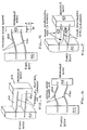
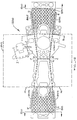
- FIGs. 8 and 9 there is shown, respectively, a side view and a top view of a side-stiffened flexural pantographic mount 822 for positioning a magnetic transducing head stack 820 included in a moveable body head assembly 812 in accord with the principles of our invention.
- Fixed body 810 is spaced from moveable body 812 by the main body of first and second parallel leaves 815 and 835, respectively.
- fixed body 810 and moveable body 812 are shown in FIGs. 8-11 as rectangular graphics around certain parts of side-stiffened flexural pantographic mount 822 to illustrate those parts of the mount, which form, respectively, the fixed body and the moveable body. It may be more clear from FIG.
- the rectangular graphics are just pictorial tools, which aid in the description of the principles of our invention, and are not themselves solid members of the mount.
- leaves 815 and 835 are parallel, the distance between the leaves at hinge plane 830 of the moveable body 812 in FIG. 8, which is called distance h1, is therefore substantially identical to the distance between the leaves at hinge plane 840 of the fixed body 810 in FIG. 8, which is called distance h2.
- a pantographic mount is obtained when the two distances h1 and h2 are equal while a non-pantographic mount is obtained when the two distances h1 and h2 are not equal.
- hinge planes 830 and 840 are also themselves substantially parallel to each other.
- the two pairs of longitudinal side extensions 825 and 845 one pair of side stiffeners 825 being integral with the respective two sides of leave 815 and the other pair of side stiffeners 845 being integral with the respective two sides of leave 835) have been found to raise the primary mode stiffness of the flexural pantographic mount 822 only a small amount while at the same time the side extensions have been found to provide the desired substantial increase in the secondary mode stiffness.
- the trapezoidal shape which is more clear from FIG.
- the front end (i.e., the end towards hinge plane 830) of a leaf is the end to which is attached the moveable body head assembly 812. It may be of interest to note that the front end of a leaf is also the end of a leaf that typically undergoes the largest deflection.
- the ten-to-one scale model also included a back end (i.e., the end towards hinge plane 840), which is the end attached to the fixed body 810.
- the back end (840) width is about 5.3 inches while the front end (830) width is about 4.0 inches.
- the length of the main body of each of the leaves as measured between front end hinge plane 830 and back end hinge plane 840 is about 6.0 inches.
- the longitudinal lengths of the respective side stiffening extensions (825, 845) are about 4.1 inches, which as mentioned above is about three-quarters the front-to-back length of the respective leaf (815, 835).
- the edge extension height as either an upward or a downward edge extension, is commensurate with the thickness of the leaf, for example, in our ten-to-one scale model the edge extension (825, 845) height is equal to about eight times the thickness of the leaf, or about 0.3 inches high. As an aside, it should be mentioned that there is no minimum height requirement for the edge extension side stiffeners to become effective.
- the primary mode frequency of mount 822 is found to have increased a small amount, that is, it increased from 11.1 hertz (Hz) to 11.7 Hz, which is an increase in primary mode stiffness of about 11 percent.
- the secondary mode frequency is found to have substantially increased, here it increased from 167 Hz to 303 Hz, which is an increase in secondary mode stiffness of about 329 percent.
- the ten-to-one scale model embodiment of a side-stiffened flexural pantographic mount for positioning a magnetic transducing head stack assembly in accord with the principles of our invention could be embodied with solid aluminum leaves.
- the leaves in the ten-to-one scale model embodiment were embodied in an aluminum mesh.
- FIGs. 8 and 9 illustrate a diamond shaped mesh 980
- the ten-to-one scale model embodiment uses a circular hole shaped mesh comprising a plurality of regularly spaced circular holes, each hole having a diameter of approximately 3/8 inches. Notwithstanding, we will later make dear that a diamond shaped mesh 980 of FIGs. 8 and 9 is actually preferred over the circular shaped mesh.
- the slight increase in primary mode frequency and the substantial increase in higher secondary mode frequency are obtained when the side stiffened aluminum leaves include a mesh structure. It can be noted that this result is also obtained when the side stiffened aluminum leaves are embodied in a solid leaf structure (versus the mesh leaf structure). It is the side stiffening which creates one beneficial result in using the principles of the present invention. It is the mesh structure which creates another beneficial result in using the principles of the prese invention.
- the mass of the leaf structure is substantially reduced when the aluminum material is omitted from the circular holes in creating a leaf structure with a circular shaped mesh.
- the side stiffened aluminum leaves with a circular shaped mesh gives rise to a structure in which the mass of the leaves is reduced by about fifty per-cent (50%).
- the lower mass leaf structure allows the leaf structure to be more responsive to external driving forces.
- the lower mass leaf structure also requires less power for deflecting the moveable body.
- a tape transport head positioning servo system 300 for providing reversible currents of varying magnitudes causing voice coil 823 to act for producing positioning motion on the head assembly 20 whereby moveable body 812 can be deflected in a manner akin to prior art electrical voice coil 23 being mounted on each mounting assembly 22 and being coupled to means for providing reversible currents of varying magnitudes causing the coil 23 to act as the movable element of a linear motor for producing the positioning motion of head assembly 20. It can be noted tha this beneficial result is not obtained when the side stiffened aluminum leaves are embodied in a solid leaf structure (versus the mesh structure).
- the circular mesh leaf structure is preferred over the solid leaf structure.
- the leaves (815, 835) shown in FIGs. 8 and 9 are formed with a plurality of diamond shaped holes exemplified by diamond shaped hole 980.
- diamond shaped hole 980 it may be noted that it is somewhat easy to discuss the diamond shaped holes 980 through the analogy that each diamond shaped hole looks similar to a baseball field, or baseball diamond, with angular lengths that are like the base paths on the baseball diamond and with corners that are like the four bases on the baseball diamond.
- the base paths have an angular length 982 of about 0.02998 inches along each of the four angular sides like angular length 982 and the corners have a corner length 981 of about 0.011314 inches along each of the four corner sides.
- the skilled artworker can form a diamond shaped aluminum mesh embodiment rather than the circular shaped mesh used in the ten-to-one scale model embodiment.
- the mass of the diamond shaped leaf mesh structure is even further reduced vis-a-vis either the side stiffened circular shaped leaf mesh structure or the side stiffened solid leaf structure, which makes the side stiffened leaf structure formed with the diamond shaped mesh even more responsive to external driving forces than either of the other two side stiffened structures.
- the circular shaped leaf mesh structure permits a reduction in the mass of the leaves of about fifty per-cent (50%) over a solid aluminum leaf structure
- the diamond shaped leaf mesh structure permits an even greater reduction in the mass of the leaves.
- Our studies have shown reductions in mass of more than sixty per-cent (60%) over a solid aluminum leaf are realizable. That further means that the mass of a diamond shaped leaf mesh structure also requires even less power to deflect the moveable body than did the circular shaped leaf mesh structure.
- the diamond shaped leaf mesh structure can be constructed in such a manner that the cross-sectional area through the width of the leaf remains approximately constant. This construction has the positive effect of distributing fatigue caused by the up and down deflection motion of the leaf over the cross-sectional width of the leaf - thereby prolonging the life of the leaf structure. To understand this advantage, consider in FIG.
- cross-sections A-A and B-B are parallel to each other and (ii) are also parallel to fixed body 810 and moveable body 812 and (iii) are also parallel to hinge planes 830 and 840 and (iv) are drawn, respectively, through (a) the mid-points of the corner sides 981 of a plurality of adjacent diamond shaped holes 980 and (b) the mid-points of the angular lengths 982 of a plurality of adjacent diamond shaped holes 980.
- cross-section A-A focus attention on cross-section A-A.
- adjacent diamond shaped holes such as 980 are separated by corner mesh remnants 983, which have a corner length 981 of about 0.011314 inches in a direction approximately perpendicular to the line of cross-section A-A and which have a width of about 0.014142 inches in a direction approximately parallel to the line of cross-section A-A, all in a full-sized one-to-one model mount 822 incorporating the principles of our invention.
- cross-section B-B focus attention on cross-section B-B.
- adjacent diamond shaped holes such as hole 980 are also separated by angular mesh remnants 984, which have an angular (base path) length mesh 982 of about 0.02998 inches in a direction, which is approximately 45 degrees to the line of cross-section B-B, and which have a width of about 0.007071 inches in a direction approximately parallel to the line of cross-section B-B, all in a full-sized one-to-one model mount 822 incorporating the principles of our invention.
- angular mesh remnant 984 in the direction of the line of cross-section B-B has an width of about 0.007071 inches, which is about one-half the width of corner mesh remnant 983 in the direction of the line cross-section A-A.
- the diamond shaped mesh can be constructed so that the cross-sectional area through the width of the leaf remains approximately constant whereby the fatigue from deflective up and down motion is distributed over the width of each cross-section of the leaves, thereby prolonging the life of the mesh leaf structure.
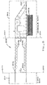
- pantographic mount 822 for positioning a magnetic transducing head stack 820 included in a moveable body head assembly 812 is shown clamped to a fixed body 810, all within an aluminum housing 1050.
- Side stiffened leaves 815 and 835 are shown clamped on either side of aluminum central spacing block 1032 by sandwiching clamping plates 1033 and bolts 1034.
- Disposed between upper clamping plate 1033 and the head of bolt 1034 is a printed circuit board 1010 to which and from which power and signals, such as the power over leads 970 to coil 823 and such as the signals over leads 980 to and from head stack 20 are provided.
- bolt 1045 is for suitably securing the fixed body 810 thereby formed to the housing 1050.
- Further window 1060 in moveable body 812 is for inserting a movement limiting device 1111 for limiting the up and the down deflection of mount 822 and its head stack 820 to maximum design limits. Movement limiting device 1111 can be suitably positioned within window 1060 by adjusting bolt 1112.
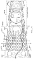
- FIG. 12 there is illustrated a flat piece of aluminum 1200, which has been embodied with diamond shaped holes 980, that is suitably shaped as a form from which a flexural pantographic mount 822 can be constructed in accordance with the principles of our invention.
- a plurality of fold lines are illustrated in FIG. 12.
- folding the piece of aluminum 1200 in an upward direction from the plane of FIG. 12 along fold lines D-D and E-E forms side stiffeners 845 along both side of leaf 835.
- folding the piece of aluminum 1200 in an upward direction from the plane of FIG. 12 along fold lines F-F and G-G forms side stiffeners 825 along both side of leaf 815.
- Folding leaf 815 around fold line C-C then brings leaf 815 over the top of leaf 835.
- Leaf 815 may also be folded along fold line M-M to create the needle node look of flexural pantographic mount 822 as viewed in FIGs. 8-11. Further folds around other fold lines (some of which are shown and other of which are readily discernible to the skill artworker from the drawings and from the earlier description) like around fold lines H-H, I-I, J-J, K-K and L-L.
- mount 822 can be formed from a single piece 1200 of aluminum.
- head stack 20 can be affixed to mount 822, for example, by epoxy to the underside of leaf 835 in the area of fold line C-C.
Landscapes
- Adjustment Of The Magnetic Head Position Track Following On Tapes (AREA)
- Moving Of Heads (AREA)
Applications Claiming Priority (2)
| Application Number | Priority Date | Filing Date | Title |
|---|---|---|---|
| US07/669,565 US5227937A (en) | 1991-03-14 | 1991-03-14 | Side-stiffened flexural pantographic mount for positioning a magnetic transducing head assembly |
| US669565 | 1991-03-14 |
Publications (3)
| Publication Number | Publication Date |
|---|---|
| EP0503762A2 true EP0503762A2 (de) | 1992-09-16 |
| EP0503762A3 EP0503762A3 (en) | 1993-01-13 |
| EP0503762B1 EP0503762B1 (de) | 1996-05-29 |
Family
ID=24686829
Family Applications (1)
| Application Number | Title | Priority Date | Filing Date |
|---|---|---|---|
| EP92301019A Expired - Lifetime EP0503762B1 (de) | 1991-03-14 | 1992-02-06 | Pantographische Halterung für einen Transducer |
Country Status (5)
| Country | Link |
|---|---|
| US (1) | US5227937A (de) |
| EP (1) | EP0503762B1 (de) |
| JP (1) | JP2579101B2 (de) |
| KR (1) | KR100244899B1 (de) |
| DE (1) | DE69211038T2 (de) |
Cited By (2)
| Publication number | Priority date | Publication date | Assignee | Title |
|---|---|---|---|---|
| EP1225644A3 (de) * | 2001-01-18 | 2005-09-07 | Ngk Insulators, Ltd. | Piezoelektrisches/elektrostriktives Bauelement und dessen Herstellungsverfahren |
| US7345406B2 (en) | 2001-01-18 | 2008-03-18 | Ngk Insulators, Ltd. | Piezoelectric/electrostrictive device |
Families Citing this family (11)
| Publication number | Priority date | Publication date | Assignee | Title |
|---|---|---|---|---|
| US6600631B1 (en) | 1989-11-27 | 2003-07-29 | Censtor Corp. | Transducer/flexure/conductor structure for electromagnetic read/write system |
| EP0648367B1 (de) * | 1992-07-01 | 1997-10-08 | Ampex Systems Corporation | Pantographische halterung fur einen magnetwandlerkopf |
| JP2717494B2 (ja) * | 1992-07-17 | 1998-02-18 | 三菱電機株式会社 | 回転磁気ヘッド装置 |
| US5377052A (en) * | 1993-06-14 | 1994-12-27 | International Business Machines Corporation | Actuator assembly for servo-controlled magnetic tape head |
| USH1573H (en) * | 1993-07-01 | 1996-08-06 | Budde; Richard A. | Reduced mass/inertia suspension |
| US5459921A (en) * | 1993-11-12 | 1995-10-24 | Seagate Technology, Inc. | Method of making a disc drive actuator arm with arm compliance compensation |
| US6229677B1 (en) | 1993-11-12 | 2001-05-08 | Seagate Technology Llc | Disc drive actuator arm assembly with outer arm z-height less than inner arm z-height |
| US6388836B2 (en) * | 1998-11-13 | 2002-05-14 | Hewlett-Packard Company | Magnetic shield for a tape drive read/write head |
| US8144431B2 (en) * | 2007-04-04 | 2012-03-27 | Hitachi Global Storage Technologies, Netherlands B.V. | Flex cable assembly for vibration reduction in HDD applications |
| US8194354B1 (en) | 2008-05-23 | 2012-06-05 | Western Digital Technologies, Inc. | Suspension assembly including a flexure tail with staggered rows of apertures |
| US9805751B1 (en) * | 2017-01-20 | 2017-10-31 | Oracle International Corporation | Record head actuator sandwiched damper plus travel limiter |
Family Cites Families (20)
| Publication number | Priority date | Publication date | Assignee | Title |
|---|---|---|---|---|
| US3931641A (en) * | 1974-08-22 | 1976-01-06 | International Business Machines Corporation | Transducer suspension mount apparatus |
| US4151569A (en) * | 1976-03-19 | 1979-04-24 | Ampex Corporation | Positionable transducer mounting structure using a piezoelectric bender element |
| US4099211A (en) * | 1976-09-13 | 1978-07-04 | Ampex Corporation | Positionable transducing mounting structure and driving system therefor |
| JPS5923226Y2 (ja) * | 1978-02-10 | 1984-07-11 | ソニー株式会社 | 回転磁気ヘツド装置のヘツド支持装置 |
| US4212043A (en) * | 1978-11-01 | 1980-07-08 | Ampex Corporation | Magnetic transducing |
| GB2050671B (en) * | 1979-06-09 | 1983-08-17 | Sony Corp | Rotary transducer head assemblies |
| JPS56153527A (en) * | 1980-04-12 | 1981-11-27 | Hitachi Denshi Ltd | Piezoelectric bimorph type transducer |
| JPS56165927A (en) * | 1980-05-24 | 1981-12-19 | Sony Corp | Vibration imparting device |
| US4485414A (en) * | 1980-07-07 | 1984-11-27 | Ampex Corporation | Servo system for positioning a movable transducing head assembly |
| DE3305618C2 (de) * | 1983-02-18 | 1986-04-30 | Deutsche Thomson-Brandt Gmbh, 7730 Villingen-Schwenningen | Kopftrommel für ein Videomagnetbandgerät |
| KR890003199B1 (ko) * | 1983-11-15 | 1989-08-26 | 마쯔시다덴기산교 가부시기가이샤 | 회전 헤드 작동장치 |
| JPS60167173A (ja) * | 1984-02-09 | 1985-08-30 | Nec Corp | ヘツドスライダ加圧支持機構 |
| US4647999A (en) * | 1984-12-03 | 1987-03-03 | Datatape Inc. | Frame for positioning transducing head |
| US4701821A (en) * | 1985-06-03 | 1987-10-20 | U.S. Philips Corporation | Helical scan tape recorder without head-tape contact in stand-by mode |
| JP2580655B2 (ja) * | 1987-12-24 | 1997-02-12 | ソニー株式会社 | 回転ヘッド装置 |
| US4860137A (en) * | 1988-03-07 | 1989-08-22 | Eastman Kodak Company | Flexure-mounted radial access apparatus for disk recorder/player |
| EP0408659A1 (de) * | 1988-04-08 | 1991-01-23 | Ampex Systems Corporation | Aufstellungsstruktur für magnetwandler |
| JP2522019B2 (ja) * | 1988-06-02 | 1996-08-07 | 三菱電機株式会社 | 回転ドラム装置 |
| JP2571111B2 (ja) * | 1988-12-05 | 1997-01-16 | アルプス電気株式会社 | 回転ヘッド式磁気記録再生装置 |
| US5047883A (en) * | 1990-02-07 | 1991-09-10 | Ampex Corporation | Pantograph head mount having double leaves integral with a rigid tip structure |
-
1991
- 1991-03-14 US US07/669,565 patent/US5227937A/en not_active Expired - Lifetime
-
1992
- 1992-02-06 EP EP92301019A patent/EP0503762B1/de not_active Expired - Lifetime
- 1992-02-06 DE DE69211038T patent/DE69211038T2/de not_active Expired - Lifetime
- 1992-03-13 KR KR1019920004152A patent/KR100244899B1/ko not_active Expired - Fee Related
- 1992-03-14 JP JP4089444A patent/JP2579101B2/ja not_active Expired - Fee Related
Cited By (3)
| Publication number | Priority date | Publication date | Assignee | Title |
|---|---|---|---|---|
| EP1225644A3 (de) * | 2001-01-18 | 2005-09-07 | Ngk Insulators, Ltd. | Piezoelektrisches/elektrostriktives Bauelement und dessen Herstellungsverfahren |
| US7024739B2 (en) | 2001-01-18 | 2006-04-11 | Ngk Insulators, Ltd. | Method of producing a piezoelectric/electrostrictive device |
| US7345406B2 (en) | 2001-01-18 | 2008-03-18 | Ngk Insulators, Ltd. | Piezoelectric/electrostrictive device |
Also Published As
| Publication number | Publication date |
|---|---|
| EP0503762B1 (de) | 1996-05-29 |
| DE69211038D1 (de) | 1996-07-04 |
| JPH05109037A (ja) | 1993-04-30 |
| EP0503762A3 (en) | 1993-01-13 |
| US5227937A (en) | 1993-07-13 |
| KR100244899B1 (ko) | 2000-02-15 |
| JP2579101B2 (ja) | 1997-02-05 |
| DE69211038T2 (de) | 1997-01-30 |
| KR920018654A (ko) | 1992-10-22 |
Similar Documents
| Publication | Publication Date | Title |
|---|---|---|
| EP0503762B1 (de) | Pantographische Halterung für einen Transducer | |
| KR0137352B1 (ko) | 헤드작동기 | |
| US4605977A (en) | Air bearing head displacement sensor and positioner | |
| US4212043A (en) | Magnetic transducing | |
| US6680826B2 (en) | Head gimbal assembly with piezoelectric microactuator | |
| EP0338698B1 (de) | Trägervorrichtung für einen Wandlerkopf | |
| US5377052A (en) | Actuator assembly for servo-controlled magnetic tape head | |
| US7614136B2 (en) | Method of producing a framing assembly | |
| US5047883A (en) | Pantograph head mount having double leaves integral with a rigid tip structure | |
| US6594118B1 (en) | Suspension system for a head-carriage assembly for a magnetic tape drive | |
| US6229677B1 (en) | Disc drive actuator arm assembly with outer arm z-height less than inner arm z-height | |
| US5699211A (en) | Boxed leaf flexural pantographic mount for a magnetic transducing head assembly | |
| JP3340206B2 (ja) | 圧電アクチュエータおよびヘッドアクチュエータ | |
| JPS6025073A (ja) | 浮動ヘツド支持装置 | |
| KR20020087101A (ko) | 동적 대칭 작동기 | |
| US5764440A (en) | Three flange carriage structure for improved voice coil support | |
| US4995711A (en) | Slide table | |
| US11948611B2 (en) | Non-right angle parallelogram PZT for suspension resonance improvement | |
| JPH0318268B2 (de) | ||
| JPS61182684A (ja) | 磁気ヘツド支持機構 | |
| US5446712A (en) | Optical system having a precision angular displacement mechanism including a flat metal spring | |
| JPS63197056A (ja) | 磁気デイスク装置 | |
| JPS6339976B2 (de) | ||
| JPH0644546A (ja) | ヘッドアクチュエータ | |
| JPH0775111B2 (ja) | 浮上型ヘッドの支持機構 |
Legal Events
| Date | Code | Title | Description |
|---|---|---|---|
| PUAI | Public reference made under article 153(3) epc to a published international application that has entered the european phase |
Free format text: ORIGINAL CODE: 0009012 |
|
| AK | Designated contracting states |
Kind code of ref document: A2 Designated state(s): AT BE CH DE DK ES FR GB GR IT LI LU NL PT SE |
|
| PUAL | Search report despatched |
Free format text: ORIGINAL CODE: 0009013 |
|
| AK | Designated contracting states |
Kind code of ref document: A3 Designated state(s): AT BE CH DE DK ES FR GB GR IT LI LU NL PT SE |
|
| 17P | Request for examination filed |
Effective date: 19930422 |
|
| RAP1 | Party data changed (applicant data changed or rights of an application transferred) |
Owner name: AMPEX SYSTEMS CORPORATION |
|
| 17Q | First examination report despatched |
Effective date: 19940405 |
|
| RBV | Designated contracting states (corrected) |
Designated state(s): DE FR GB |
|
| GRAH | Despatch of communication of intention to grant a patent |
Free format text: ORIGINAL CODE: EPIDOS IGRA |
|
| GRAA | (expected) grant |
Free format text: ORIGINAL CODE: 0009210 |
|
| RBV | Designated contracting states (corrected) |
Designated state(s): DE GB |
|
| AK | Designated contracting states |
Kind code of ref document: B1 Designated state(s): DE GB |
|
| REF | Corresponds to: |
Ref document number: 69211038 Country of ref document: DE Date of ref document: 19960704 |
|
| PLBE | No opposition filed within time limit |
Free format text: ORIGINAL CODE: 0009261 |
|
| 26N | No opposition filed | ||
| REG | Reference to a national code |
Ref country code: GB Ref legal event code: 732E |
|
| REG | Reference to a national code |
Ref country code: GB Ref legal event code: IF02 |
|
| PGFP | Annual fee paid to national office [announced via postgrant information from national office to epo] |
Ref country code: DE Payment date: 20100219 Year of fee payment: 19 Ref country code: GB Payment date: 20100202 Year of fee payment: 19 |
|
| GBPC | Gb: european patent ceased through non-payment of renewal fee |
Effective date: 20110206 |
|
| REG | Reference to a national code |
Ref country code: DE Ref legal event code: R119 Ref document number: 69211038 Country of ref document: DE Effective date: 20110901 |
|
| PG25 | Lapsed in a contracting state [announced via postgrant information from national office to epo] |
Ref country code: GB Free format text: LAPSE BECAUSE OF NON-PAYMENT OF DUE FEES Effective date: 20110206 |
|
| PG25 | Lapsed in a contracting state [announced via postgrant information from national office to epo] |
Ref country code: DE Free format text: LAPSE BECAUSE OF NON-PAYMENT OF DUE FEES Effective date: 20110901 |