EP0648367B1 - Pantographische halterung fur einen magnetwandlerkopf - Google Patents
Pantographische halterung fur einen magnetwandlerkopf Download PDFInfo
- Publication number
- EP0648367B1 EP0648367B1 EP93916929A EP93916929A EP0648367B1 EP 0648367 B1 EP0648367 B1 EP 0648367B1 EP 93916929 A EP93916929 A EP 93916929A EP 93916929 A EP93916929 A EP 93916929A EP 0648367 B1 EP0648367 B1 EP 0648367B1
- Authority
- EP
- European Patent Office
- Prior art keywords
- leaf
- mount
- leaves
- stiffness
- stiffening means
- Prior art date
- Legal status (The legal status is an assumption and is not a legal conclusion. Google has not performed a legal analysis and makes no representation as to the accuracy of the status listed.)
- Expired - Lifetime
Links
- 230000002463 transducing effect Effects 0.000 title claims abstract description 14
- 238000005452 bending Methods 0.000 claims abstract description 13
- 229910052782 aluminium Inorganic materials 0.000 claims description 12
- XAGFODPZIPBFFR-UHFFFAOYSA-N aluminium Chemical compound [Al] XAGFODPZIPBFFR-UHFFFAOYSA-N 0.000 claims description 12
- 239000000463 material Substances 0.000 claims description 10
- 239000004411 aluminium Substances 0.000 claims 2
- 230000008878 coupling Effects 0.000 claims 1
- 238000010168 coupling process Methods 0.000 claims 1
- 238000005859 coupling reaction Methods 0.000 claims 1
- 239000003351 stiffener Substances 0.000 abstract description 23
- 206010052904 Musculoskeletal stiffness Diseases 0.000 description 37
- 238000012360 testing method Methods 0.000 description 21
- 238000005259 measurement Methods 0.000 description 13
- 230000000712 assembly Effects 0.000 description 10
- 238000000429 assembly Methods 0.000 description 10
- 230000032258 transport Effects 0.000 description 8
- 238000013016 damping Methods 0.000 description 5
- 230000009471 action Effects 0.000 description 4
- 230000000694 effects Effects 0.000 description 4
- 230000007246 mechanism Effects 0.000 description 4
- 229910052751 metal Inorganic materials 0.000 description 4
- 239000002184 metal Substances 0.000 description 4
- 239000007787 solid Substances 0.000 description 4
- 230000006872 improvement Effects 0.000 description 3
- 230000000670 limiting effect Effects 0.000 description 3
- 230000002787 reinforcement Effects 0.000 description 3
- 230000002441 reversible effect Effects 0.000 description 3
- 239000002131 composite material Substances 0.000 description 2
- 230000009977 dual effect Effects 0.000 description 2
- 230000005284 excitation Effects 0.000 description 2
- 238000011068 loading method Methods 0.000 description 2
- 230000010355 oscillation Effects 0.000 description 2
- 238000005192 partition Methods 0.000 description 2
- 239000004593 Epoxy Substances 0.000 description 1
- 230000002159 abnormal effect Effects 0.000 description 1
- 230000002238 attenuated effect Effects 0.000 description 1
- 238000006243 chemical reaction Methods 0.000 description 1
- 230000000052 comparative effect Effects 0.000 description 1
- 238000010276 construction Methods 0.000 description 1
- 238000010586 diagram Methods 0.000 description 1
- 238000006073 displacement reaction Methods 0.000 description 1
- 229910000701 elgiloys (Co-Cr-Ni Alloy) Inorganic materials 0.000 description 1
- 238000007373 indentation Methods 0.000 description 1
- 230000010354 integration Effects 0.000 description 1
- 239000007769 metal material Substances 0.000 description 1
- 238000000034 method Methods 0.000 description 1
- 230000003287 optical effect Effects 0.000 description 1
- 230000036961 partial effect Effects 0.000 description 1
- 230000035515 penetration Effects 0.000 description 1
- 230000009467 reduction Effects 0.000 description 1
- 230000002829 reductive effect Effects 0.000 description 1
- 230000003014 reinforcing effect Effects 0.000 description 1
- 230000003252 repetitive effect Effects 0.000 description 1
- 230000004044 response Effects 0.000 description 1
- 238000003466 welding Methods 0.000 description 1
Images


Classifications
-
- G—PHYSICS
- G11—INFORMATION STORAGE
- G11B—INFORMATION STORAGE BASED ON RELATIVE MOVEMENT BETWEEN RECORD CARRIER AND TRANSDUCER
- G11B5/00—Recording by magnetisation or demagnetisation of a record carrier; Reproducing by magnetic means; Record carriers therefor
- G11B5/48—Disposition or mounting of heads or head supports relative to record carriers ; arrangements of heads, e.g. for scanning the record carrier to increase the relative speed
- G11B5/58—Disposition or mounting of heads or head supports relative to record carriers ; arrangements of heads, e.g. for scanning the record carrier to increase the relative speed with provision for moving the head for the purpose of maintaining alignment of the head relative to the record carrier during transducing operation, e.g. to compensate for surface irregularities of the latter or for track following
- G11B5/584—Disposition or mounting of heads or head supports relative to record carriers ; arrangements of heads, e.g. for scanning the record carrier to increase the relative speed with provision for moving the head for the purpose of maintaining alignment of the head relative to the record carrier during transducing operation, e.g. to compensate for surface irregularities of the latter or for track following for track following on tapes
- G11B5/588—Disposition or mounting of heads or head supports relative to record carriers ; arrangements of heads, e.g. for scanning the record carrier to increase the relative speed with provision for moving the head for the purpose of maintaining alignment of the head relative to the record carrier during transducing operation, e.g. to compensate for surface irregularities of the latter or for track following for track following on tapes by controlling the position of the rotating heads
-
- G—PHYSICS
- G11—INFORMATION STORAGE
- G11B—INFORMATION STORAGE BASED ON RELATIVE MOVEMENT BETWEEN RECORD CARRIER AND TRANSDUCER
- G11B5/00—Recording by magnetisation or demagnetisation of a record carrier; Reproducing by magnetic means; Record carriers therefor
- G11B5/48—Disposition or mounting of heads or head supports relative to record carriers ; arrangements of heads, e.g. for scanning the record carrier to increase the relative speed
- G11B5/52—Disposition or mounting of heads or head supports relative to record carriers ; arrangements of heads, e.g. for scanning the record carrier to increase the relative speed with simultaneous movement of head and record carrier, e.g. rotation of head
- G11B5/53—Disposition or mounting of heads on rotating support
- G11B5/531—Disposition of more than one recording or reproducing head on support rotating cyclically around an axis
- G11B5/534—Disposition of more than one recording or reproducing head on support rotating cyclically around an axis inclined relative to the direction of movement of the tape, e.g. for helicoidal scanning
Definitions
- This invention relates to mounting assemblies for magnetic signal transducers, such as write/read (or record/reproduce) heads used for storing and retrieving information in or from a magnetic storage medium, like magnetic tape, and, more particularly, this invention relates to a mounting assembly for holding and supporting and varying the position of such magnetic signal transducers.
- helical-scan magnetic tape transports employ one or more mounting assemblies for supporting and adjustably positioning a magnetic transducing head in a rotating drum.
- One such assembly is disclosed in US-A-4,212,043.
- adjustable mounts are secured to the interior of the rotating drum and extend radially toward the periphery of the drum with the transducer or head protruding through an opening in the drum to scan the recording tracks on a magnetic tape curved around the periphery of the drum in a helical path.
- Those adjustable mounts permit the head to move laterally with respect to the length direction of a recorded track.
- Each adjustable mount also known as a flexural pantographic mechanism, includes a pair of parallel bending or pivoting leaf members anchored at one set of ends to a fixed body.
- the leaf members extend as cantilevered beams with the transducing head assembly mounted near the opposite set of ends in a manner so that the head assembly can operate as a moveable body.
- Each leaf assembly is suitably constructed so that, when a control voltage is applied such as by a tape transport head positioning servo system to a voice coil assembly, the leaf members deflect accordingly, thereby displacing the transducing head supported on the moveable body.
- the extent and direction of the deflection of the head is proportional to and a function of the amplitude and polarity of the control voltage applied to the voice coil.
- the head When used in combination with a servo system feedback circuit, the head may be positioned in an optimum location for following a tape track, which has been recorded on the magnetic tape medium.
- Such a head positioning arrangement has some disadvantages.
- the inherent flexibility of usually long, thin head positioning leaf members sets up undesirable resonance in the leaf members under rapid and repetitive flexure loadings. Such resonances also result in undesirable deflections under repeated flexures of the leaf members.
- the occurrence of such conditions in the leaf members under the desired loading sequence can severely impair the ability of a head mounted on a leaf member to accurately follow a magnetic tape track.
- Such undesirable conditions can be substantially aggravated unless the frequencies of higher mode vibrations, also called oscillations in the art, are raised substantially higher than the frequency bandwidth of a suitable closed loop servo system of which the mounting assembly is a part.
- the primary, or first, mode stiffness K of a leaf member is defined as the ratio F/D, where F is a component of a force that is perpendicular to the plane of a leaf member and D is the deflection of the moveable body. Since the power utilized in producing the force, and hence the deflection, increases with increasing primary mode stiffness, it is desirable to design the leaves in such a manner so as to minimize the primary mode stiffness. At the same time, it is desirable to raise the frequencies of the vibrations of the higher order modes of the leaf members so as to attenuate the undesirable excitation from the higher frequency oscillations mentioned above.
- the higher order mode frequencies can be raised by increasing the higher order mode stiffness of the leaf members to values beyond the designed bandwidth of the closed loop servo system, i.e., the higher mode frequencies can be increased so that any undesirable excitation that they may put upon the servo system is so significantly attenuated that the servo system, for all practical purposes, is not subjected to those undesirable effects of the higher order mode vibrations.
- U.S. Patent 4,212,043 discloses a solution to this problem wherein the leaf thickness is not uniform. Instead, stiffening plate members are attached to the central portion of both sides of a much thinner leaf to form laminated leaf composites. This solution, however, can be costly since more parts and additional assembly steps are usually required. Moreover, the stresses on the end portions of the leaves which do not contact the stiffening members are so highly concentrated that it often necessitates that a costly, very thin, high yield strength material be used for this composite laminate construction to maintain the same low primary mode stiffness as with an equivalent constant leaf thickness pantograph mechanism.
- mounts are subjected to torsional vibrations, that is, twisting actions about the longitudinal center line of the mount.
- torsional vibrations that is, twisting actions about the longitudinal center line of the mount.
- mounts indude multiple head stacks some of which are disposed from the longitudinal centerline at the head or free end of the mount. Misalignments due to such torsional actions serve to impact on their signal strength, despite otherwise relatively accurate tracking.
- the preferred embodiment of the present invention is an improved boxed leaf stiffened pantograph mounting structure, or mount, for holding and varying the position of a moveable head in a helical scan automatic scan tracking magnetic tape transport.
- the mount exhibits an acceptably low primary mode stiffness and a suitably increased higher order mode stiffness with increased resistance to torsional stresses and is adapted for use in a magnetic tape transport employing a closed loop servo system having a specified frequency bandwidth.
- the mount includes a moveable body such as a magnetic transducing head assembly as well as first and second parallel spaced apart elongated flexible yet similar flexural pantographic leaves configured at the free ends thereof for attachment to a fixed body.
- Each flexural pantographic leaf has two opposite ends, two opposite edges and a defined, and preferably uniform, thickness. One set of opposite ends is connected to the fixed body, while the other set of ends is connected to the moveable body.
- Each leaf includes first and second leaf edge extensions, which act as side stiffeners, each edge extension being integrally formed with one of the opposite edges of the corresponding leaf.
- An auxiliary web-like stiffener is added to each leaf and includes tab projections generally perpendicular to the plane of the main body portion of the web for connection to the leaf and for providing transverse or lateral stiffening.
- Each auxiliary web stiffener is separately formed and configured for attachment to the respective leaf to the side stiffeners and edge extensions of openings in the leaf to form a box-like cross-sectional configuration in conjunction with the side leaf edge extensions.
- the web stiffeners are disposed in the space intermediate the leaf members.
- the main body portion of each leaf and the tab projections of the auxiliary stiffeners are configured, dimensioned and arranged for connection to one another in both the longitudinal and transverse directions.
- the openings are formed in each leaf at locations such that the flexing surface of the leaves, at the connection to the fixed body and at the connection to the moveable body, are smaller width strap sections, substantially less than the width of the corresponding portion of the leaf.
- Each leaf side stiffener and auxiliary stiffener is positioned and constructed so as to leave the leaf thickness unaltered and to leave the value of the primary mode stiffness substantially unaltered, while at the same time raising the stiffness of the higher mode vibrations to values at which their corresponding natural mode frequencies are substantially higher than the specified frequency bandwidth and, in addition, increasing the torsional stiffness of the mount for better dimensional control of the transducers which are mounted to it.
- a flexural pantographic mount is shown and described for use in a helical scan magnetic tape transport employing a closed loop servo system having a specified frequency bandwidth.
- the mount indudes a fixed body and a moveable body such as a magnetic transducing head assembly.
- First and second parallel spaced apart elongated flexible yet similar leaves, formed of similar material, have opposite ends, opposite edges and uniform thickness. One set of the opposite ends of the leaves is connected to the fixed body, the other set of opposite ends being connected to the moveable body.
- the leaves each include first and second edge extensions, or side stiffening, strips of similar material integrally formed with the opposite edges of each corresponding leaf to form a side along the edge of the leaf with the side lying in a plane generally orthogonal to the plane of the leaf.
- edge stiffener with its leaf occurs without altering the thickness of either the edge or the leaf so as to maintain the value of the primary mode stiffness as a substantially unaltered value while at the same time the frequencies of the higher order natural mode vibrations are raised to values substantially greater than the specified bandwidth of the dosed loop system.
- the head assembly 20 includes first and second axially projecting transducer assemblies 22, 24, at the head or terminal end thereof, each of which may be one or more read/write heads.
- the pantograph mount, generally designated 25, includes three functional portions, these being the moveable end, which is the transducer end of the head assembly 20; the fixed end, which is the opposite end suitably configured for connection to a clamping assembly, generally designated 28; and the intermediate flexural portion, which indudes first and second leaf members 30, 31, which are generally planar members which are generally identical in thickness, configuration and dimension.
- Each leaf includes side leaf stiffening integrally formed members 30a, 30b and 31a, 31b (See also FIGURES 6, 7 and 12), such as described in the aforementioned incorporated patent application.
- first and second polygonally configured openings 33, 34 are formed in leaf 30 (with a corresponding pair of openings 35, 36 formed in the leaf 31), with the configurations of the openings, each being symmetrical with respect to the longitudinal axis or centerline of the leaf member 30.
- the rearward opening 33 (the opening closer to the damping portion) is generally triangularly configured, while the forward opening 34 is generally trapezoidally configured.
- each of the openings 33-36 is formed to indude tab portions which, in the unbent blank, extend into the opening, and which, when bent or formed, extend in a plane orthogonal to the plane of the leaf 30, 31, and along a line which is transverse to the plane of the side leaf stiffening members 30a, 30b, 31a, 31b.
- the base 33a (and 35a) of the triangular opening 33 (and 35) is positioned so that it lies generally in the plane of the clamp block of the clamping mechanism 28, while the long base of the trapezoidally configured opening 34 (and 36) is positioned so that it lies generally in the plane forming the non-free end of the moveable body portion of the head assembly 20.
- first and second reinforcing or auxiliary stiffening web members 40, 41 are formed as a blank of mesh metallic material, preferably aluminum, with provision thereon for tab portions to be bent and coact with the tab portions about the openings 33-36 for attachment thereto to provide a box-like configuration for each leaf 30, 31 in the flexural portion of the head assembly 20.
- the moveable body portion of the head assembly is generally designated 44, and includes the box-like portion of the blank forward of the leaves 30, 31.
- the moveable body portion 44 of the head assembly 20 is provided with an electrical voice coil 48 configured, dimensioned and arranged for cooperative engagement with a stator element assembly, generally designated 50 (See also FIGURE 12), which includes an annular opening 52 into which the voice coil 48 extends for electromagnetic actuation in response to control signals via the coil 48.
- the voice coil 48 is mounted on the underside of the moveable body portion 44 and is coupled to a tape transport head positioning servo system for providing reversible currents of varying magnitudes causing the coil to act as the movable element of a linear motor for positioning of the head assembly 20.
- the stator element assembly 50 of the linear motor includes a permanent magnet member 54 which will be described in more detail later.
- the head assembly 20 when mounted within a rotating drum assembly, the head assembly 20 is subjected to tremendous force, such as centrifugal force, and, while rotating under this force which operates on the leaves 30, 31, the transducers 22, 24 are traversing a prescribed linear path within a window opening in order to enable the heads, under control of the servo system, to faithfully track the magnetically recorded track during reproduce operations.
- the weight of the leaves 30, 31, the moveable body 44, the heads 22, 24 and the voice coil 48 measures about 0.35 grams at rest, but under the centrifugal forces that are generated during operation, such as rotation at 100 revolutions per second, the equivalent mass of such a rotating assembly can be in the neighborhood of 544 grams (1.2 pounds).
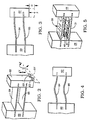
- FIGURE 2 there is diagrammatically illustrated a prior art head assembly which includes a fixed body 60, a moveable body 62 suitably connected to the fixed body 60 by a pair of generally parallel, generally identical, cantilevered leaf elements 64, 65.
- the block designated moveable body 62 is essentially the forward portion of a moveable head assembly which includes the transducers and voice coil.
- the first and second parallel leaves 64, 65 are of uniform lengths and widths, which, in the prior art, are formed of thin "Elgiloy" spring material.
- One set of ends of the leaves is embedded in, or connected to, fixed body 60, for example, by means of a clamping structure while an opposite set of ends is embedded in, or connected to, moveable assembly 62.
- the embedded ends of the leaves 64, 65 remain locked, or affixed, or attached to, or fastened in position while the main body of the leaves 64, 65 are effectively hinged at the embedded ends.
- the lower front end of the moveable body has been depicted with first and second horizontally aligned transducers 63, 63' positioned in alignment with an elongate rectangular block which represents a recorded magnetic tape track 63.
- a dashed line, designated CL projects from the face of the moveable body 62 at about the center thereof in a direction perpendicular thereto, and generally represents the longitudinal centerline of the mount.
- a double ended vertical arrow V depicts the normal direction of travel and force on the moveable body 62 while the double ended arced arrow about the centerline CL designated T shows the torsional forces acting on the moveable body 62, and thus the heads 63, 63'.
- the moveable body 62 here embodied as the head assembly
- the moveable body 62 is deflected a distance D in the direction of the force, that is at right angles to the plane of the leaves.
- the leaves 64, 65 have a primary stiffness K equal to the ratio F/D and exhibit a characteristic "S" shape, which is representative of a primary mode shape.
- the leaves 64, 65 exhibit a primary mode shape
- the leaves 64, 65 have a secondary mode shape which is an inverted somewhat "U" shape with a central upward bulge, which is substantially in the direction of the force F, again in a direction at right angles to the plane of the leaves.
- this mode due to the characteristic of the bend, there is a tendency for the moveable body 62 to move closer to the fixed body 60, resulting in the relaxation of the head to tape contact.
- the leaves 30, 31 are provided with a boxed-leaf configuration by providing a leaf configuration having the first and second openings 33, 34 and 35, 36 and the leaf side stiffening extensions 30a, 30b and 31a, 31b in cooperative relation with the stiffening web members 40, 41.
- the configuration, dimension and arrangement of the tab portions of the blanks used to construct the web stiffeners and leaves are such that lateral, as well as transverse stiffening is provided to the flexural portion of the assembly to minimize or eliminate the effects of primary and secondary mode flexing, while minimizing or eliminating the effects of torsional flexing.
- FIGURE 6 shows a side view of the mount 25
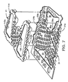
- FIGURE 7 shows a partial exploded enlarged perspective view of one leaf 31 and one web stiffening member 41
- FIGURES 8 and 9 show the one-piece metal blanks, generally designated 70 and 110, respectively, for forming the main body portion of the mount 25 and the web stiffening member 40 or 41.
- the side view of the pantograph mount 25 and voice coil 48 assembly has been delineated, by broken lines, into portions corresponding to the diagrammatic illustration of FIGURE 5, that is the fixed body portion 28, the moveable body portion 44 and the flexural portion therebetween.
- the blank 70 of FIGURE 8 has been delineated into sections to show the part thereof used to form one of the constructed portions.
- the blank 70 is a one-piece mesh structure formed as a planar configuration from metal stock, preferably aluminum, of a uniform thickness.
- the blank 70 is shown as being divided into functional parts, the central portion of which is delineated with a broken line rectangle designated 44, this being the part used to form the moveable body portion 44.
- the extreme left and right ends of the blank 70 are designated 28a and 28b, respectively, these being the two clamping edge portions utilized for damping to the block clamping assembly 28 to provide the fixed body.
- the portions of the blank 70 intermediate the moveable body portion 44 and damping edge portions 28a, 28b are designated 30, 31, these being the leaf forming portions which have been designated with like reference numerals.
- the clamping edge portions 28a and 28b are formed with suitable mounting apertures, a detailed description of which is unnecessary.
- the leaf 30 is formed of a mesh structure with a first isosceles trangularly configured opening 33 and a second trapezoidally configured opening 34, both of which are symmetrical to the longitudinal centerline of the blank 70, that is, the centerline extending from left to right as viewed in the drawing.
- the base edge 33a of the opening 33 lies on a line which lies in the plane of the forward edges of the blocks of the damping assembly 28, this being the flex line or pivot of the flexural leaf 30 relative to the fixed body 28.
- first and second flexural strap hinge portions 30y and 30z (along with similar hinge portions 31y and 31z on leaf 31). These hinge portions do not extend the width of the structure and, as such provide a minimum amount of force which is resistant to flexure.
- the trapezoidal openings have a base line at the ends of which are like flexural strap hinge portions 34y, 34z and 36y, 36z, each of which is generally equal in width to one another and to the flexural hinge portions 33y, 33z and 35y, 35z, In this manner, flexing is about two pairs of narrow width strap like hinge portions.
- the blank 70 includes first and second tabs 33b and 33c projecting inwardly into the opening 33, the tabs 33b and 33c being configured for being bent along bend lines.
- the blank 70 is shown with a plurality of bend lines, shown as broken lines with an alphabetical designation. Note that a plurality of fold lines are illustrated in FIGURE 8. For example, folding the piece of aluminum blank 70 in a downward direction from the plane of FIGURE 8 along fold lines D-D and E-E forms side stiffeners 30a and 30b along both sides of leaf 30. Similarly, folding the piece of aluminum 70 in an upward direction from the plane of FIGURE 8 along fold lines F-F and G-G forms side stiffeners 31a and 31b along both sides of leaf 31.
- Folding leaf 30 around fold line C-C then brings leaf 30 over the top of leaf 31.
- the portion 44 of the blank 70 indudes a plurality of outwardly extending tab and side projections, such as coil side panels 72 and 74, cross tabs 73 and 75 extending outwardly from side panels 72 and 74, respectively.
- Side panels 72 and 74 are configured for bending along bend lines H-H and I-I, respectively, which are collinear with bend lines F-F and G-G of side edge stiffeners 31a and 31b, respectively.
- Cross tabs 73 and 74 form a part of a rear lateral bulkhead and indude bend lines K-K and J-J, respectively, which lie along a line transverse or perpendicular to the bend lines I-I and H-H, respectively.
- Side panel 74 has an angularly projecting strap portion 77 for folding along bend line L, which is generally parallel to bend line H-H.
- said panel 72 has an outwardly projecting forward (relative to the heads) bulkhead panel portion 80, which includes a narrow neck portion 78 with bend line M, the width of neck portion 78 being about equal to the width of strap portion 77.
- Panel portion 80 also includes five other bend lines, these being lines N-N, O-O and P-P, each of which is along a line almost perpendicular to the bend line I-I of side panel 72; with short bend lines Q and R defining the bend portion of first and second bulkhead lateral support tabs 83 and 84, respectively.
- Bend line O-O defines the folded end of a partition support tab 85
- bend line P-P defines an end of the bulkhead bottom support tab 86.
- the main body portion 81 of the bulkhead panel portion is an essentially rectangular part configured to define the length and width of the one end of the moveable body portion 44, and spans the distance between the spaced leaves 30, 31, with the width corresponding to the width of the leaves 30, 31 at the bulkhead panel.
- the second body portion 82 of the bulkhead panel portion 80 forms part of an upper surface lateral brace for the forward or front bulkhead panel portion 80.
- the bulkhead lateral support tabs 83 and 84 are bent in the same direction along lines Q and R, respectively, to an angle generally perpendicular to the plane of main body portion 81, while bottom support tab 86 is bent along line P-P in a direction perpendicular to the plane of the main body portion 81 in a direction opposite to the direction of bending of tabs 83 and 84, that is the tab 86 is bent toward the front end or nose of the moveable body portion 44.
- the blank 70 includes a coil support portion, generally designated 90, which includes a large circular opening 91 having a diameter approximating that of the voice coil 48.
- the coil support portion 90 is generally trapezoidally configured and is defined on the one side by the bend line C-C, which forms the nose of the moveable body portion 44, and on the rear side by bend line S-S, with the sides thereof being defined by the bend lines H-H and I-I of side panels 72, 74, respectively.
- the projection 94 is folded along a bend line T-T, which forms the base of the trapezoidal opening 34 of leaf 30.
- the projections 93 and 94 serve as structural reinforcement as well as aligned coplanar attachment surfaces for connection to cross tabs 73 and 75 to form the bulkhead at one junction of the leaves 30, 31.
- the moveable body portion 44 of the blank 70 includes an enlarged opening, generally designated 100, which, in part, overlies the coils support area defined by coil receiving opening 91 and, in part, overlies the portion of the mount 25 between the two bulkhead assemblies, formed essentially in major part by panel portion 80 and by the just described coaction of cross tabs 73, 75 with projections 93, 94.
- the leading or head end of the moveable body portion 44 is needle nosed or tapered, with the side panels 72, 74 having a rectangularly configured portion coextensive with a triangularly configured portion, the latter having the apex thereof terminating at bend line C-C.
- the lateral edges of the structure surrounding opening 100 are provided with outwardly extending stiffening tabs, arranged in pairs, such as opposing pair 100a, 100b, and the second opposing pair 100c, 100d.
- Bend line U-U is provided for folding tabs 100b and 100d, which are located adjacent one another
- bend line V-V is provided for folding tabs 100a and 100c, which are adjacent one another.
- the tab pair 100a, 100b, when folded, serve to provide stiffening as well as connection surfaces for the edges of the rectangular portions of the side panels 72, 74
- tabs 100c, 100d when folded, serve to provide stiffening as well as connection surfaces for the hypotenuse of the triangular portions of the side panels 72, 74, respectively.
- each indude first and second tabs are bent inwardly toward one another at roughly ninety degrees to the plane of the leaf.
- Each trapezoidal opening 34, 36 in leaves 30, 31, respectively, includes three tab projections (in addition to tabs 93, 94 previously discussed), these being tabs 24a-24c and 36a-36c, each of which is likewise bent inwardly at right angles to the plane of the leaf. These tabs serve to provide opening edge reinforcement and serve as attachment points for the auxiliary web stiffener 40 or 41, both of which are identical.
- the web stiffeners 40, 41 are formed from a blank 110, as shown in FIGURE 9, and, in general overall configuration, is somewhat trapezoidally configured.
- the tabs 110a and 110b when bent, coact with and are attached to tabs 30a and 30b of leaf 30, respectively.
- the left end of blank 110 is generally V-shaped to conform geometrically to the V-shaped portion of the triangular opening 33 of leaf 30, with the tab projections 103b and 103c of blank 110 corresponding in dimension, angular orientation and configuration for coaction with and attachment to tabs 33b and 33c, respectively, of the opening 33.
- the indentation is partially trapezoidal, with tabs 104a, 104b and 104c, arranged for overlying and connection to corresponding tabs 24a, 24b and 24c formed within opening 24 of leaf 30.
- the blank 110 is provided with elongate triangular openings arranged in mirror image relationship, with each having a respective tab 105, 106 protruding therein, these tabs being configured for bending along two fold lines to form central brace connection points to the leaf 30 when assembled. It is to be understood that a like blank 110 would have the tabs bent in the proper direction for attachment to leaf 31 at the appropriate location relative to openings 35 and 36.
- the arrangement and attachment of a web stiffening member 41 to the leaf 31 is best illustrated in FIGURE 7 which depicts the parts in exploded perspective relation.
- mount 25 can be formed from a single piece or blank 70 of aluminum with the structural addition of the formed web stiffening member 40, 41 to provide the boxed leaf configuration provided by a pair of identical blanks 110. Thereafter heads 22, 24 can be affixed to mount 25, for example, by epoxy to the underside of leaf 31 in the area of fold line C-C.
- the mount 25 is shown in its assembled condition, along with the attached voice coil 48.
- the leaves 30, 31 are generally parallel with the web stiffening members 40, 41 in opposing back to back relation in the space therebetween.
- the rear portion which includes the free ends of the leaves 30, 31 are suitably clamped within blocks of the damping assembly 28 to maintain this parallel relationship.
- the base lines 33a and 35a of the triangular openings 33 and 35 of the leaves 30, 31, are in a common plane with the forward surface of the clamping block assembly 28, resulting in narrow hinge members in the form of the pairs of flexural strap hinge members 30y and 30z of leaf 30 and 31y, 31z of leaf member 31.
- the flexural hinge strap pairs 34y, 34z and 36y, 36z perform a like function.
- FIGURE 11 shows the mount 25 with the transducers 22 and 24 attached with their respective electrical leads 22a and 24a. Similarly, the voice coil leads 48a and 48b are shown attached.
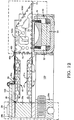
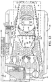
- FIGURES 12 and 13 Referring to the top and side views, respectively, of FIGURES 12 and 13, of the side-stiffened flexural pantographic mount 25 for positioning a magnetic transducing head stack 22, 24, the mount 25 and voice coil 48 assembly are induded in a moveable body head assembly 20 which is shown clamped to a fixed body 28, all within an aluminum housing 120. Side stiffened leaves 30a and 31a are shown clamped on either side of aluminum central spacing block 28a by sandwiching clamping plates 28b, 28c and bolts 29.
- a printed circuit board 122 Disposed between upper clamping plate 28b and the head of bolt 29 is a printed circuit board 122 to which and from which power and signals, such as the power over leads 48a and 48b to voice coil 48 and such as the signals over leads 22a and 24a to and from head stacks 22 and 24, respectively, are provided. Also bolt 124 is for suitably securing the fixed body 28 thereby formed to the housing 120. Further window 125 in moveable body 44 is for inserting a movement limiting device 127 for limiting the up and the down deflection of mount 25 and its head stacks 22, 24 to maximum design limits. Movement limiting device 127 can be suitably positioned within window 125 by adjusting bolt 127.
- FIGURES 6, 8, 12, and 13 show fixed body 28 and moveable body 44 as rectangular broken line graphics around certain parts of side-stiffened flexural pantographic mount 25 to illustrate those parts of the mount 25, which form, respectively, the fixed body and the moveable body.
- FIGURE 6 the rectangular graphics are just pictorial tools, which aid in the description of the principles of our invention, and are not themselves solid members of the mount.
- hinge planes a line between hinge straps 30y and 30z on the fixed body end and a line between hinge straps 34y and 34z on the moveable body end as shown in FIGURE 8) are also themselves substantially parallel to each other.
- the following example illustrates that primary mode/secondary mode stiffness finding for a ten-to-one scale model, i.e. a ten times enlarged scale model, of a side-stiffened flexural pantographic mount for positioning a magnetic transducing head stack.
- a like ten times scale model has been utilized with the boxed-leaf pantograph mount 25 according to the present invention.
- the trapezoidal shape which is more clear from FIGURE 9 when viewed looking at the top of leaf 30 of flexural pantographic mount 25 helps reduce the mass of the respective leaves 30, 31.
- the triangular openings 33, 35 and the trapezoidal openings 34, 36 reduce the mass, while providing tabs for transverse bracing and structural support of the leaves 30, 31.
- the front end of a leaf is the end to which is attached the moveable body 44 transducer heads 22, 24. It may be of interest to note that the front end of a leaf is also the end of a leaf that typically undergoes the largest deflection, as well as torsional deflection.
- the ten-to-one scale model also induded a back end, which is the end attached to the clamping assembly or fixed body 28.
- the back end width is about 133 mm (5.3 inches) while the front end width is about 100 mm (4.0 inches).
- the length of the main body of each of the leaves 30, 31 as measured between the front end and back end hinge is about 150 mm (6.0 inches).
- the longitudinal lengths of the respective side stiffening extensions 30a, 31a are about 4.1 inches, which as mentioned above is about three-quarters the front-to-back length of the respective leaf 30, 31.
- the edge extension height as either an upward or a downward edge extension, is commensurate with the thickness of the leaf, for example, in our ten-to-one scale model the edge extension 30a, 31a, height is equal to about eight times the thickness of the leaf, or about 8 mm (0.3 inches) high.
- the web stiffening members are formed of aluminum of similar thickness, with the tabs formed to provide a depth approximating 8 mm (0.3 inches) the same as that of the depth of the side stiffening edge extensions.
- the primary mode frequency of mount 25 is found to have remained about the same as that with the side stiffening edge extensions alone, that is a primary mode frequency of about 11.7 Hz.
- the secondary mode frequency is found to have substantially increased, from 167 Hz to 303 Hz, which is an increase in secondary mode stiffness of about 329 percent.
- the primary mode frequency was about the same with a slight increase in the secondary mode frequency to about 320 Hz.
- the side stiffening edge extensions alone torsional resistance was not significantly improved, but with the boxed-leaf flexural pantograph mount 25 with the web stiffening members 40, 41, substantial resistance to torsional deflection was noted.
- the ten-to-one scale model embodiment uses a circular hole shaped mesh comprising a plurality of regularly spaced circular holes, in both blanks 70 and 110, with each hole having a diameter of approximately 7 mm (9/32 inches).
- the mass of the leaf structure is substantially reduced when the aluminum material is omitted from the circular holes in creating a leaf structure with a circular shaped mesh, a reduction in mass approximating about fifty per-cent (50%) compared to a solid leaf structure.
- the lower mass leaf structure allows the leaf structure to be more responsive to external driving forces.
- the lower mass leaf structure also requires less power for deflecting the moveable body.
- Electrical power is provided over power leads 201 to voice coil lead leads 48a, 48b by a tape transport head positioning servo system 200 for providing reversible currents of varying magnitudes causing voice coil 48 to act for producing a positioning motion on the head assembly 20 whereby moveable body 44 can be deflected in a manner akin to prior art electrical voice coil 48 being mounted on each head assembly 20 and being coupled to means for providing reversible currents of varying magnitudes causing the coil 48 to act as the movable element of a linear motor for producing the positioning motion of head assembly 20.
- FIGURES 14 and 15 there are diagrammatic illustrations, side and front views, of test arrangements utilized to determine the stiffness factors of the subject mount 25, in both the longitudinal deflection as well as torsional deflection.
- the mount 25 has a vertical force applied as indicated by the vertically extending arrow 210, while a dial gauge in proximity to the force measures the deflection.
- the primary stiffness was measured to be 150 g/mm (8.4 lb./in).
- FIGURE 15 there is shown a front diagrammatic view with only one leaf shown for descriptive purposes.
- the vertical centerline is the center of the leaf, designated 30, on the longitudinal axis and is shown as being fixed, as a consequence of the clamping action of the clamping block assembly 28 (not shown). Torsional reaction takes place about this center point.
- a force F1 designated by reference numeral 215, is positioned below the leaf 30 on the right extremity, and an equal and opposite force F (arrow 217) is positioned on the left extremity, these two forces being the same distance from the centerline, that is, about 100 mm (4 inches).
- a dial displacement gauge 220 is positioned on the left about 88 mm (3 1/2 inches) from the centerline, with the results of the clockwise (CW) and counterclockwise (CCW) deflection versus load being given in the following table: TABLE 2 LOAD DEFLECTION (CCW) DEFLECTION (CW) 454 g. (1 lb.) 0.138 mm (0.0055 in.) 0.125 mm (0.0050 in) 908 g. (2 lb.) 0.27 mm (0.011 in) 0.25 mm (0.0100 in) 1362 g (3 lb) 0.4 mm (0.016 in) 0.39 mm (0.0155 in)
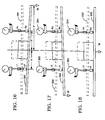
- FIGURES 15 through 18 depict test arrangements for the simple solid leaf pantograph mount of the prior art and the side edge stiffened pantograph mount of the invention disclosed in the above mentioned incorporated patent application.
- the leaf in each has been designated 300, with the dotted line depiction thereof being designated 300', this representing the leaf 300 in its untwisted or undeflected state.
- First and second dial gauge meters 302, 304 are fixedly positioned equidistant from the centerline of the leaf 300 and set to a quiescent position with the leaf undeflected to establish a zero baseline for deflection or twisting measurements.
- FIGURE 16 shows the weight "W” on the right terminal end of the leaf 300 for clockwise deflection measurements
- FIGURE 17 shows the weight "W” on the left terminal end of leaf 300 for counterclockwise deflection measurements
- FIGURE 18 has the weight "W” along the centerline of the leaf 300 for establishing deflection measurements, in contrast to the torsional measurements of FIGURES 16 and 17.
- FIGURES 16-18 bear designations in the upper left corner of each figure, such as W(R) CASE, W(L) CASE, and W(C) CASE, these being, respectively, test arrangements with the weight applied at the right, at the left and at the center, respectively.
- Other designations appear in the figures adjacent the gauges 302, 304, such as L1, L2, L3, L4, L5 and L6 (adjacent left gauge 302) and R1, R2, R3, R4, R5 and R6 (adjacent right gauge 304), the designations L1-6 and R1-6, respectively, referring to the respective left and right undeflected or untwisted initial positions of the leaf 300 and serve as baseline measurements from which deflection is measured for the particular test in the particular view.
- L2 and R2 are the measurements of the deflection from the baseline position for the left and right sides respectively of leaf 300.
- the distance from the centerline of the leaf 300 to either free end is about 150 mm (6 inches), while the distance between the centerline and the axial centerline of both of the gauges 302 and 304 is about 100 mm (4 inches).
- K(Torsion R) 279 x 10 -3 m.kg/degree (23.79 in.-lb./degree)
- K(Torsion L) 178 x 10 -3 m.kg/degre 15.394 in.-lb./degree
- K (Deflection) 84.6 gm/mm (4.733 lb./in.)
- K(Torsion R) 262 x 10 -3 m.kg/degree (22.699 in.-lb./degree)
- K(Torsion L) 163 x 10 -3 m.kg/degree (14.159 in.-lb./degree)
- K (Deflection) 84.5 gm/mm (4.722 lb./in.)
- K (TORSION R) 268 x 10 -3 m.kg/degree (23.24 in.-lb./degree)
- K (TORSION L) 170 x 10 -3 m.kg/degree (14.78 in.-lb./degree)
- K (TORSION avg ) 219 (19.01 in.-lb./degree)
- K (DEFLECTION avg ) 84.6 gm/mm (4.73 lb./in)
- K(Torsion R) 447 x 10 -3 m.kg/degree (38.77 in.-lb./degree)
- K(Torsion L) 561 x 10 -3 m.kg/degree (48.68 in.-lb./degree)
- K (Deflection) 136 grams/mm (7.6422 lb./in.)
- K(Torsion R) 433 m.kg/degree (37.63 in.-lb./degree)
- K(Torsion L) 549 m.kg/degree (47.67 in.-lb./degree)
- K (Deflection) 136 grams/mm (7.64 lb./in.)
- K (TORSION R) 440 x 10 -3 m.kg/degree (38.2 I-in.-lb./degree)
- K (TORSION L) 555 x 10 -3 m.kg/degree (48.175 in.-lb./degree)
- K (TORSION avg. ) 497 x 10 -3 m.kg/degree (43.1875 in.-lb./degree)
- K (DEFLECTION avg ) 138 grams/mm (7.74 lb./in)
- the overall stiffness factors for each type of mount were determined by dividing the torsional stiffness factor by the deflection stiffness factor using the above tabulated average results, with the following conductions: SIMPLE PANTOGRAPH MOUNT 2593 mm 2 /degree (4.02 in 2 /degree) SIDE STIFFENED PANTOGRAPH MOUNT 3646 mm 2 /degree (5.653 in 2 /degree) BOXED-LEAF PANTOGRAPH MOUNT 7159 mm 2 /degree (11.1 in 2 /degree)
Landscapes
- Adjustment Of The Magnetic Head Position Track Following On Tapes (AREA)
- Supporting Of Heads In Record-Carrier Devices (AREA)
Claims (14)
- Halterung zum Halten und zum Verstellen der Position eines magnetischen Übertragungsmittels (22, 24), wobei die Halterung aufweist:einen festen Körper (28);einen beweglichen Körper (44) mit darauf befestigten Übertragungsmitteln (22, 24);erste und zweite, in parallelem Abstand gehaltene, längliche, biegsame Blätter (30, 31) mit ersten Enden davon, an denen der feste Körper (28) angebracht ist, und zweiten Enden davon, an denen der bewegliche Körper (44) angebracht ist, wobei die auf die Bewegung des beweglichen Körpers ansprechenden Blätter einer dynamischen Verbiegung und Drehkräften ausgesetzt und so gestaltet sind, daß sie um eine Distanz auslenken und weiterhin daran angepaßt sind, eine Grundmodussteifigkeit zu zeigen und daran angepaßt sind, eine höhere Steifigkeit als die Grundmodussteifigkeit zu zeigen, underste und zweite Seitenversteifungsmittel (30a, 30b, 31a, 31b), die mit jedem der entsprechenden Blätter einteilig so ausgebildet sind, daß höhere Vibrationen zu Frequenzwerten angehoben werden, die deutlich höher sind als eine festgelegte Bandbreite eines Servosystems mit geschlossener Regelschleife, als deren Teil die Befestigung vorgesehen ist, ohne gleichzeitig die Dicke des entsprechenden Blattes zu ändern und ohne wesentliche Änderung der Grundmodussteifigkeit des entsprechenden Blattes,gekennzeichnet durch:
erste und zweite, an die Seitenverstärkungsmittel (30a, 30b, 31a, 31b) und an mittlere Teile (35b, 35c, 36a, 36b, 36c) der Blätter in Bauart mit kastenförmigem Querschnitt angebrachte Hilfsversteifungsmittel (40, 41), um eine Kreuzverstrebung zur Verfügung zu stellen, die die Drehsteifigkeit der Halterung erhöht, ohne die Grundmodussteifigkeit wesentlich zu ändern. - Halterung nach Anspruch 1, bei der jedes Blatt (30, 31) eine Maschenstruktur aufweist.
- Halterung nach Anspruch 1, bei der jedes Seitenversteifungsmittel (30a, 30b, 31a, 31b) eine nach außen gerichtete Verlängerung eines Teils jeder Kante des entsprechenden Blattes (30, 31) umfaßt, die ungefähr um einen rechten Winkel bezüglich der Ebene des Hauptkörperteils des Blattes gebogen ist.
- Halterung nach Anspruch 1, bei der jedes Seitenverstärkungsmittel (30a, 30b, 31a, 31b) im wesentlichen an einer entsprechenden Kante des Hauptkörpers eines jeden Blattes zentriert ist, wobei der Hauptkörper denjenigen Teil des Blattes darstellt, der sich zwischen dem festen Körper (28) und dem beweglichen Körper (44) erstreckt.
- Halterung nach Anspruch 1, bei der jedes der Hilfsversteifungsmittel (40, 41) ein gewebeartiges Element ist, wobei Teile davon zum Zusammenwirken mit und zur Anbringung an die Seitenversteifungsmittel (30a, 30b, 31a, 31b) gebogen sind.
- Halterung nach Anspruch 1, bei der die Blätter (30, 31) und die Hilfsversteifungsmittel (40, 41) ungefähr die gleiche Dicke aufweisen und aus dem gleichen Material hergestellt sind.
- Halterung nach Anspruch 1, wobei jedes der Blätter (30, 31) und der Hilfsversteifungsmittel (40, 41) aus dem gleichen maschenartigen Material im wesentlichen gleicher Dicke hergestellt sind.
- Halterung nach Anspruch 1, bei der die Blätter (30, 31) jeweils erste und zweite Öffnungen (35, 36) umfassen, die Symmetrie bezüglich deren Längsachse aufweisen, und wobei jede Öffnung (35, 36) einen Basisbereich entlang der Biegelinie der Blätter an dem Verbindungspunkt mit dem festen Körper (28) bzw. an dem Verbindungspunkt mit dem beweglichen Körper (44) einschließt.
- Halterung nach Anspruch 8, bei der die Blätter (30, 31) und der bewegliche Körper (44) durch Biegen eines Rohteils aus maschenartigem Aluminiummaterial hergestellt sind.
- Halterung nach Anspruch 9, bei der jedes der Hilfsversteifungsmittel (40, 41) durch Biegen eines gewebeförmigen Rohteils aus maschenartigem Aluminiummaterial hergestellt ist.
- Halterung nach Anspruch 8, bei der eine der Öffnungen (35) dreieckförmig ausgestaltet ist und erste und zweite Nasenvorsprünge (35b, 35c) umfaßt, die auf beiden Seiten der Öffnung unter Abknickung von im wesentlichen rechten Winkeln zu der Ebene der Blätter (30, 31) ausgebildet sind, um eine Kreuzverstärkung und Mittel zur Anbringung der Hilfsversteifungsmittel (40, 41) zur Verfügung zu stellen.
- Halterung nach Anspruch 11, bei der die zweite Öffnung (36) im wesentlichen trapezförmig ausgestaltet ist und wenigstens erste und zweite Nasenvorsprünge (36b, 36c) umfaßt, die auf wenigstens zwei Seiten der Öffnung unter Abknickung von im wesentlichen rechten Winkeln zu der Ebene der Blätter (30, 31) ausgebildet sind, um eine Kreuzverstärkung und Mittel zur Anbringung der Hilfsversteifungsmittel (40, 41) zur Verfügung zu stellen.
- Halterung nach Anspruch 12, bei der die Hilfsversteifungsmittel (40, 41) Nasenvorsprünge (103b, 103c; 104b, 104c; 110a, 110b) umfassen, die dimensioniert, ausgestaltet und angeordnet sind unter Abknickung von im wesentlichen rechten Winkeln bezüglich der Ebene deren Hauptkörperteils zur Anbringung an entsprechend gelegene Teile der Blätter (30, 31) und der Nasenvorsprünge (35b, 35c; 36b, 36c) der Öffnungen.
- Magnetbandtransportvorrichtung für Schrägspur-Verfahren, die eine Rotationsabtasteinrichtung aufweist, die eine Magetwandlerkopfanordnung (20, 22, 24) mittels einer Halterung trägt, wobei die Halterung umfaßt:einen festen Körper (28);erste und zweite, im wesentlichen ebene und parallele, längliche, biegsamen Blätter (30, 31), wobei jedes Blatt ein erstes an den festen Körper (28) angebrachtes Ende und ein zweites an die Kopfanordnung (20, 22, 24) angebrachtes Ende aufweist und wobei die Blätter, die auf die Bewegung der beweglichen Kopfanordnung ansprechen, dynamischen Auslenkungen und Drehkräften ausgesetzt und daran angepaßt sind, um eine Distanz auszulenken, und daran angepaßt sind, eine Grundmodussteifigkeit zu zeigen, und daran angepaßt sind, eine höhere Steifigkeit als die Grundmodussteifigkeit zu zeigen; undintegral mit den entgegengesetzten Kanten des entsprechenden Blattes (30, 31) verbundene Mittel (30a, 30b; 31a, 31b) zur Verfügungstellung eine Seitenkantensteifigkeit;gekennzeichnet durch:
erste und zweite Gewebemittel (40, 41), von denen jedes einen im wesentlichen ebenen Hauptkörperteil und gebogene Vorsprünge (103, 104, 110) daran aufweist, die zur Kopplung an eines des Blätter (30, 31) mit dem Hauptkörperteil in im wesentlichen paralleler Beziehung mit dem entsprechenden Blatt ausgestaltet, dimensioniert und angeordnet sind, so daß die so entworfene Halterung im wesentlichen den Wert ihrer Grundmodussteifigkeit beibehält, während die Frequenzen der höheren natürlichen Schwingungsmoden auf Werte angehoben werden, die deutlich höher sind als eine spezifizierte Bandbreite eines Servosystems mit geschlossener Regelschleife zur Regelung der Auslenkung der Blätter und des Übertragers, bei gleichzeitiger wesentlicher Anhebung der Drehsteifigkeit der Halterung.
Applications Claiming Priority (3)
| Application Number | Priority Date | Filing Date | Title |
|---|---|---|---|
| US90698592A | 1992-07-01 | 1992-07-01 | |
| US906985 | 1992-07-01 | ||
| PCT/US1993/006295 WO1994001862A1 (en) | 1992-07-01 | 1993-07-01 | Pantographic mount for a magnetic transducing head |
Publications (2)
| Publication Number | Publication Date |
|---|---|
| EP0648367A1 EP0648367A1 (de) | 1995-04-19 |
| EP0648367B1 true EP0648367B1 (de) | 1997-10-08 |
Family
ID=25423350
Family Applications (1)
| Application Number | Title | Priority Date | Filing Date |
|---|---|---|---|
| EP93916929A Expired - Lifetime EP0648367B1 (de) | 1992-07-01 | 1993-07-01 | Pantographische halterung fur einen magnetwandlerkopf |
Country Status (4)
| Country | Link |
|---|---|
| US (1) | US5699211A (de) |
| EP (1) | EP0648367B1 (de) |
| DE (1) | DE69314488T2 (de) |
| WO (1) | WO1994001862A1 (de) |
Families Citing this family (7)
| Publication number | Priority date | Publication date | Assignee | Title |
|---|---|---|---|---|
| US5930072A (en) * | 1997-05-06 | 1999-07-27 | Seagate Technology, Inc. | Head-disk assembly for reducing noise coupled into magnetoresistive head preamplifiers |
| US5872687A (en) * | 1997-08-25 | 1999-02-16 | International Business Machines Corporation | Transducer suspension system |
| JPH1196526A (ja) * | 1997-09-24 | 1999-04-09 | Internatl Business Mach Corp <Ibm> | アクチュエータ・アーム・アセンブリ及びディスク記憶装置 |
| US6578893B2 (en) | 2000-10-02 | 2003-06-17 | Ajs Automation, Inc. | Apparatus and methods for handling semiconductor wafers |
| US8635784B2 (en) * | 2005-10-04 | 2014-01-28 | Applied Materials, Inc. | Methods and apparatus for drying a substrate |
| US8194354B1 (en) | 2008-05-23 | 2012-06-05 | Western Digital Technologies, Inc. | Suspension assembly including a flexure tail with staggered rows of apertures |
| US9805751B1 (en) | 2017-01-20 | 2017-10-31 | Oracle International Corporation | Record head actuator sandwiched damper plus travel limiter |
Family Cites Families (9)
| Publication number | Priority date | Publication date | Assignee | Title |
|---|---|---|---|---|
| US4212043A (en) * | 1978-11-01 | 1980-07-08 | Ampex Corporation | Magnetic transducing |
| JPS56165927A (en) * | 1980-05-24 | 1981-12-19 | Sony Corp | Vibration imparting device |
| JPS59180855A (ja) * | 1983-03-30 | 1984-10-15 | インタ−ナシヨナル ビジネス マシ−ンズ コ−ポレ−シヨン | ヘッドサスペンション装置付きディスク・ファイル |
| JPS59207065A (ja) * | 1983-05-09 | 1984-11-24 | Nec Corp | 浮動ヘツド支持装置 |
| JPS6163974A (ja) * | 1984-09-05 | 1986-04-02 | Matsushita Electric Ind Co Ltd | ピツクアツプ装置 |
| JPH03503692A (ja) * | 1988-04-08 | 1991-08-15 | アムペクス コーポレイション | 磁気トランスデューサのための改良取付け構造 |
| JPH0371476A (ja) * | 1989-08-11 | 1991-03-27 | Nec Corp | 磁気ヘッド支持体 |
| US5047883A (en) * | 1990-02-07 | 1991-09-10 | Ampex Corporation | Pantograph head mount having double leaves integral with a rigid tip structure |
| US5227937A (en) * | 1991-03-14 | 1993-07-13 | Ampex Corporation | Side-stiffened flexural pantographic mount for positioning a magnetic transducing head assembly |
-
1993
- 1993-07-01 WO PCT/US1993/006295 patent/WO1994001862A1/en not_active Ceased
- 1993-07-01 DE DE69314488T patent/DE69314488T2/de not_active Expired - Fee Related
- 1993-07-01 EP EP93916929A patent/EP0648367B1/de not_active Expired - Lifetime
-
1994
- 1994-11-28 US US08/345,559 patent/US5699211A/en not_active Expired - Lifetime
Also Published As
| Publication number | Publication date |
|---|---|
| DE69314488D1 (de) | 1997-11-13 |
| WO1994001862A1 (en) | 1994-01-20 |
| DE69314488T2 (de) | 1998-05-20 |
| US5699211A (en) | 1997-12-16 |
| EP0648367A1 (de) | 1995-04-19 |
Similar Documents
| Publication | Publication Date | Title |
|---|---|---|
| EP0338698B1 (de) | Trägervorrichtung für einen Wandlerkopf | |
| US5115363A (en) | Head/gimbal assembly having low stiffness cross band flexure | |
| CA1149509A (en) | Magnetic transducing head mount | |
| EP0644530B1 (de) | Trägersystem für Wandler | |
| US4853811A (en) | Magnetic disk drive with low profile head-suspension system | |
| US5184265A (en) | Magnetic head suspension assembly in a disk drive | |
| JP2729031B2 (ja) | 共振応答を改善したヘッド・ガイド・アセンブリ | |
| WO1998009275A1 (en) | Head suspension having reduced torsional vibration | |
| US20040066585A1 (en) | Dual stage suspension with PZT actuators | |
| US6741424B1 (en) | Head suspension with rail and stiffener combination | |
| EP0267749B1 (de) | Montage von magnetischen Köpfen | |
| EP0648367B1 (de) | Pantographische halterung fur einen magnetwandlerkopf | |
| EP0503762B1 (de) | Pantographische Halterung für einen Transducer | |
| EP0557710A2 (de) | Kopfaufhängungseinheit in einem Plattenantrieb | |
| US5815348A (en) | Load beam with inward stiffening channel | |
| US6594118B1 (en) | Suspension system for a head-carriage assembly for a magnetic tape drive | |
| US5107383A (en) | Transducer supporting device for supporting a transducer in a rotary disk storage unit | |
| US5812343A (en) | Base plate with improved swage performance and reduced mass | |
| JPH0766644B2 (ja) | ヘツド支持装置 | |
| DE69024027T2 (de) | Magnetkopf-Aufhängungseinheit in einem Plattenantrieb. | |
| USH1425H (en) | Head suspension assembly having improved frequency response, accurate head positioning and minimized flying variation | |
| WO2001073765A1 (en) | Dynamically symmetric actuator | |
| DE60317673T2 (de) | Kopfaufhängung, kopfantrieb und plattengerät | |
| CA2229239A1 (en) | Suspension having reduced torsional mode gain and sensitivity | |
| US7149057B2 (en) | Open-channel torsion bend section |
Legal Events
| Date | Code | Title | Description |
|---|---|---|---|
| PUAI | Public reference made under article 153(3) epc to a published international application that has entered the european phase |
Free format text: ORIGINAL CODE: 0009012 |
|
| 17P | Request for examination filed |
Effective date: 19950126 |
|
| AK | Designated contracting states |
Kind code of ref document: A1 Designated state(s): DE FR GB |
|
| 17Q | First examination report despatched |
Effective date: 19951212 |
|
| GRAG | Despatch of communication of intention to grant |
Free format text: ORIGINAL CODE: EPIDOS AGRA |
|
| GRAH | Despatch of communication of intention to grant a patent |
Free format text: ORIGINAL CODE: EPIDOS IGRA |
|
| GRAH | Despatch of communication of intention to grant a patent |
Free format text: ORIGINAL CODE: EPIDOS IGRA |
|
| GRAA | (expected) grant |
Free format text: ORIGINAL CODE: 0009210 |
|
| AK | Designated contracting states |
Kind code of ref document: B1 Designated state(s): DE FR GB |
|
| REF | Corresponds to: |
Ref document number: 69314488 Country of ref document: DE Date of ref document: 19971113 |
|
| ET | Fr: translation filed | ||
| REG | Reference to a national code |
Ref country code: GB Ref legal event code: 732E |
|
| PLBE | No opposition filed within time limit |
Free format text: ORIGINAL CODE: 0009261 |
|
| STAA | Information on the status of an ep patent application or granted ep patent |
Free format text: STATUS: NO OPPOSITION FILED WITHIN TIME LIMIT |
|
| 26N | No opposition filed | ||
| REG | Reference to a national code |
Ref country code: GB Ref legal event code: IF02 |
|
| PGFP | Annual fee paid to national office [announced via postgrant information from national office to epo] |
Ref country code: DE Payment date: 20090626 Year of fee payment: 17 |
|
| PGFP | Annual fee paid to national office [announced via postgrant information from national office to epo] |
Ref country code: GB Payment date: 20100630 Year of fee payment: 18 Ref country code: FR Payment date: 20100805 Year of fee payment: 18 |
|
| PG25 | Lapsed in a contracting state [announced via postgrant information from national office to epo] |
Ref country code: DE Free format text: LAPSE BECAUSE OF NON-PAYMENT OF DUE FEES Effective date: 20110201 |
|
| REG | Reference to a national code |
Ref country code: DE Ref legal event code: R119 Ref document number: 69314488 Country of ref document: DE Effective date: 20110201 |
|
| GBPC | Gb: european patent ceased through non-payment of renewal fee |
Effective date: 20110701 |
|
| REG | Reference to a national code |
Ref country code: FR Ref legal event code: ST Effective date: 20120330 |
|
| PG25 | Lapsed in a contracting state [announced via postgrant information from national office to epo] |
Ref country code: FR Free format text: LAPSE BECAUSE OF NON-PAYMENT OF DUE FEES Effective date: 20110801 |
|
| PG25 | Lapsed in a contracting state [announced via postgrant information from national office to epo] |
Ref country code: GB Free format text: LAPSE BECAUSE OF NON-PAYMENT OF DUE FEES Effective date: 20110701 |