EP0499202A2 - Dispositif pour déterminer la distribution de pression dans un trajet limité et procédé pour sa fabrication - Google Patents
Dispositif pour déterminer la distribution de pression dans un trajet limité et procédé pour sa fabrication Download PDFInfo
- Publication number
- EP0499202A2 EP0499202A2 EP92102255A EP92102255A EP0499202A2 EP 0499202 A2 EP0499202 A2 EP 0499202A2 EP 92102255 A EP92102255 A EP 92102255A EP 92102255 A EP92102255 A EP 92102255A EP 0499202 A2 EP0499202 A2 EP 0499202A2
- Authority
- EP
- European Patent Office
- Prior art keywords
- pressure sensors
- pressure
- jacket
- carrier element
- evaluation circuit
- Prior art date
- Legal status (The legal status is an assumption and is not a legal conclusion. Google has not performed a legal analysis and makes no representation as to the accuracy of the status listed.)
- Withdrawn
Links
Images
Classifications
-
- G—PHYSICS
- G01—MEASURING; TESTING
- G01F—MEASURING VOLUME, VOLUME FLOW, MASS FLOW OR LIQUID LEVEL; METERING BY VOLUME
- G01F23/00—Indicating or measuring liquid level or level of fluent solid material, e.g. indicating in terms of volume or indicating by means of an alarm
- G01F23/14—Indicating or measuring liquid level or level of fluent solid material, e.g. indicating in terms of volume or indicating by means of an alarm by measurement of pressure
- G01F23/18—Indicating, recording or alarm devices actuated electrically
- G01F23/185—Indicating, recording or alarm devices actuated electrically for discrete levels
-
- G—PHYSICS
- G01—MEASURING; TESTING
- G01F—MEASURING VOLUME, VOLUME FLOW, MASS FLOW OR LIQUID LEVEL; METERING BY VOLUME
- G01F23/00—Indicating or measuring liquid level or level of fluent solid material, e.g. indicating in terms of volume or indicating by means of an alarm
- G01F23/14—Indicating or measuring liquid level or level of fluent solid material, e.g. indicating in terms of volume or indicating by means of an alarm by measurement of pressure
- G01F23/16—Indicating, recording, or alarm devices being actuated by mechanical or fluid means, e.g. using gas, mercury, or a diaphragm as transmitting element, or by a column of liquid
- G01F23/164—Indicating, recording, or alarm devices being actuated by mechanical or fluid means, e.g. using gas, mercury, or a diaphragm as transmitting element, or by a column of liquid using a diaphragm, bellow as transmitting element
-
- Y—GENERAL TAGGING OF NEW TECHNOLOGICAL DEVELOPMENTS; GENERAL TAGGING OF CROSS-SECTIONAL TECHNOLOGIES SPANNING OVER SEVERAL SECTIONS OF THE IPC; TECHNICAL SUBJECTS COVERED BY FORMER USPC CROSS-REFERENCE ART COLLECTIONS [XRACs] AND DIGESTS
- Y10—TECHNICAL SUBJECTS COVERED BY FORMER USPC
- Y10T—TECHNICAL SUBJECTS COVERED BY FORMER US CLASSIFICATION
- Y10T29/00—Metal working
- Y10T29/49—Method of mechanical manufacture
- Y10T29/49002—Electrical device making
- Y10T29/49082—Resistor making
- Y10T29/49103—Strain gauge making
Definitions
- the invention relates to a device for determining the pressure distribution over a limited distance and a method for its production with the features of the preamble of claim 1 and 14, and the use of such devices.
- DE-A1-35 33 070 describes a fill level indicator of this type, in which recesses are machined on the inside of the container wall at vertical intervals, into which pressure measuring cells provided with strain gauges are inserted. These cells are connected to an evaluation circuit. When the container is emptied, one cell after the other is relieved of the pressure generated by the filling material and the signal emitted by it indicates the current filling level.
- the formation of such recesses and the assembly of the pressure transducers is very complex and labor intensive. In addition, leakage problems can occur between the recesses and the pressure cells.
- DE-A1-36 41 482 describes a level sensor using a membrane switch with a disk-like housing which is attached to an opening of the container with the membrane.
- DE-C2-33 27 047 describes a liquid level detector which is suspended from a coaxial cable in the container and has temperature-sensitive sensors which hang at different heights in the container.
- DE-C3-31 48 383 is concerned with a level indicator for a motor vehicle fuel tank with a probe on which individual PTC thermistors are arranged at different intervals.
- the DD-A1-247 971 is concerned with a level indicator in which a piezoresistive pressure transducer hanging from a line is immersed in the liquid at a certain height.
- the invention has for its object to provide a device for determining the pressure distribution over a limited distance, which is simple and robust, is inexpensive to manufacture and can be used in a variety of ways. Furthermore, a simple and inexpensive method for producing such devices and particularly preferred uses of such devices are to be specified.
- this object is achieved by a device with the features of claim 1 or a method with the features of claim 14 and uses according to claim 15.
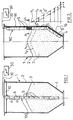
- a container or tank 1 is shown with a wall 2.
- Material 3 is filled in the interior of the container, for example liquid or bulk material, which can be removed via an outlet funnel 4.
- Several practically punctiform pressure sensors 5 are arranged on or in an elongated carrier element 6 of the device 100 at a certain, preferably uniform, vertical distance a from one another.
- the carrier element 6 can have any cross section and is fastened to an upper support 10 and hangs in the container 1 to a substantial depth, namely to the bottom thereof.
- the support element 6 is designed to be tensile in its vertical longitudinal extent, but relatively elastic in the transverse direction (see illustration in FIGS. 3 to 5), so that radial deformations of the support element 6 on the pressure sensors 5 cannot cause any measurement falsifications .
- the carrier element 6 is preferably provided with additional reinforcing inserts 7 (see FIG. 3), so that the pressure sensors 5 always remain in the container 1 at the same height.
- FIG. 2 shows an alternative arrangement of a carrier element 16 for the pressure sensors 5.
- the carrier element 16 is fastened to the inner wall 2 of the container 1, for example welded or glued on.
- One of the pressure sensors 5 approximately halfway inside the carrier element 16 is shown schematically as a partial section.
- the pressure or measured value distribution shown in FIG. 2 on the right as a schematic diagram essentially results, according to which the pressure sensor 5 ′ arranged lowest in the outlet funnel 4 indicates the highest measured value in accordance with the static pressure .
- the pressure decreases continuously in accordance with the altitude of the individual pressure sensors 5.
- measurement values are obtained which, according to the diagram, lie approximately on a straight line as a measurement curve b , the intersection of which with the ordinate axis thus gives the current fill level h 1.
- the measuring curve b and its course, in particular its slope can be precisely defined with the individual measured values, so that a particularly high measuring accuracy and measuring reliability result.
- This evaluation can easily be carried out using known summing or integrating methods with the aid of a likewise known evaluation circuit 50.
- a simple example is the determination of the intersection of the straight line (or other curve) with the ordinate axis. Due to the large number of measured values, an exact continuous level indicator is given as the intersection h 1 between two adjacent pressure sensors.
- the lowest pressure sensor 5 'in the outlet funnel 4 indicates a measured value of, for example, 60 bar.
- the following measured values are then 50 bar, 40 bar, 30 bar, 20 bar and 10 bar, so that straight line b results with a slope of 60 ° to the axis of the abscissa. If, as is indicated by dashed lines, the fill level falls when emptying, the pressure sensor 5 ′′ lying below the section line AA is no longer acted on and all individual measured values are, for example, 10 bar lower. Even then, the curve of the measurement curve must again be shown here as a straight line b ', the intersection of which with the ordinate axis gives the fill level h 2.
- the measurement curves b and b 'etc. thus form a family of curves parallel to one another, so that deviations therefrom can be determined and easily corrected in the evaluation circuit 50.
- the measurement curves b can also represent parabolic sections or other curves.
- the measurement curves are theoretically predetermined by the respective distances between the pressure sensors 5.
- the device is calibrated, for example, by determining the actual curve shape that is representative and characteristic of the later current level measurements (here the straight line b with a gradient of 60 °) and the family of curves, preferably when the container 1 is completely full, since all pressure sensors have 5 measured values deliver and thus the determination of the measurement curve b is carried out most reliably with as many measurement values as possible.
- the level can then be gradually reduced and the corresponding measured values can be determined again.
- the curve shape can also be determined by simulation in an arrangement on a reduced scale.
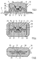
- FIG. 3 shows a cross-sectional view of the device 110 along the cross-sectional line AA of FIG. 2.
- the carrier element 16 consists essentially of the profile rail 17, which is preferably H-shaped and is preferably made of metal and has two side webs 19 and a connecting web 18.
- the carrier element 16 is attached by means of ends 24 of the side webs 19 bent at right angles to the inner wall 2 of the container, for example welded or glued, possibly also screwed on at a few points, as is indicated in the left half of FIG. 3. In this case, a few screw points 24 in the upper region of the container 1 are sufficient, which is generally easily accessible.
- the connecting web 18 the pressure sensors 5 are inserted, which is hermetically sealed from the material 3 with a permanently elastic sheath 8.
- the pressure sensors 5 have a pressure sensor membrane 9 on the side facing away from the pressure p and are connected to the evaluation circuit 50, for example a microprocessor known per se, with cables 30 also running inside the casing 8 of the carrier element 16.
- a pressure sensor which can preferably be used is described, for example, in EP-A-0 394 632 (US Pat. No. 4,984,468).
- the reinforcement inserts 7 can be provided in the region of the side webs 19 and be formed by high-strength sheathing of the cables 30 or, conversely, the reinforcement inserts 7 can be designed as signal-transmitting cables.
- a hat-shaped holder 11 of the pressure sensor 5 is inserted, which in turn receives a sensor body with the pressure sensor membrane 9.
- FIG. 4 shows a cross-sectional view along the line A-A in FIG. 2 of a modified embodiment of a carrier element 26.
- a profile rail 27 is surrounded on all sides by a casing 28.
- This device is particularly suitable for hanging use according to FIG. 1.
- Pressure sensors 25 essentially consist of a hat-shaped, ceramic sensor body 21 with a thin membrane 22, on the back of which known strain gauge measuring strips, preferably in thick-film technology, are provided generate a change in resistance proportional to the pressure p and thus the deformation of the membrane 22 and transmit a corresponding signal via the cable 30 to the evaluation circuit 50.
- the pressure introduction to the membrane 22 takes place via a pressure introduction piston 14, which is guided on its outer circumference with low friction via an annular gap 15 filled with elastomeric material in the holder 23.
- the elastomeric material adheres firmly to the surfaces of the annular gap 15. It is in particular vulcanized and introduced without bubbles, as described in the earlier applications EP-A-0 440 012 (US patent application No. 648,259) and EP-A-0 440 011 ( U.S. Patent Application No. 648,804), which is incorporated by reference.
- EP-A-0 440 012 US patent application No. 648,259
- EP-A-0 440 011 U.S. Patent Application No. 648,804
- FIG. 5 shows a further embodiment of a device 100 or 110 with a carrier element 36 which has a profiled rail 37 and is designed to be relatively flat in the manner of a strip or a belt, so that it is about the axis c is relatively flexible; thus, the carrier element 36 can also be attached to an incompletely flat inner wall 2 of the container without the risk of measurement errors.
- the carrier element 36 can thus even be rolled up and stored and transported as roll goods. 1, the flexible design allows a certain deflection without measurement errors.
- the pressure sensor 35 is designed without an additional pressure introduction piston 14 and pin 12 (FIG. 4). Rather, the elastomeric material of the casing 38 acts directly on the sensor body 31 and the diaphragm 32 when pressure is applied. It should be noted that in all the exemplary embodiments, the pressure sensors 5 etc. are completely encapsulated in the carrier element, so that the material 3 cannot damage them . This results in a very wear-resistant and robust measuring device with high measuring accuracy and measuring reliability.
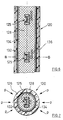
- FIGS. 6 and 7 show a section of an exemplary embodiment of a device 120 according to the invention with pressure sensors 125 arranged at a distance from one another (see FIGS. 3 and 5), which are completely embedded in a body 128 made of elastomeric material with a round, preferably circular or oval cross section .
- the body 128 is surrounded by a jacket 126 which is inelastic in the axial and preferably also in the circumferential direction, but is deformable in the radial direction.
- the Sheath 126 can be, for example, a plastic tube in which axially extending inelastic threads 132, for example made of metal or plastic, are embedded circumferentially. Instead of an axial extension, a spiral course of the threads 132 could also be used.
- the outer surface of the jacket 126 should be wear-resistant in most applications, particularly when level measurement in bunkers.
- the jacket 126 could also be formed by a (metal) fabric.
- the body 128 consists of the most incompressible elastomeric material, for example bubble-free natural or silicone rubber or similar materials, such as are mentioned for example in EP-PS 0 145 001 (US Pat. No. 4,644,805).
- any other pressure sensors can also take their place.
- the body 128 is firmly attached in the jacket 126 to its inner jacket surface in the exemplary embodiment by elastomeric material which is introduced into an annular gap 134.
- a first possibility of producing the body 128 is to arrange the pressure sensors 125 in a tubular shape.
- the pressure sensors 125 there is either at least one line mechanically (and electrically) connecting all the sensors to the evaluation circuit 50 or a type of cable harness 136 if a single line is provided for each pressure sensor.
- the individual pressure sensors 125 or, depending on the rigidity, the line pieces lying between them are provided with corresponding radial spacing elements, as shown in FIG the casting technique is common.
- a closed, straight tube can be used as the shape into which the “armored” pressure sensor / line arrangement is inserted or pulled, or the tube is longitudinally divided, which means the insertion of the pressure sensor / Line arrangement easier.
- a (longitudinally divided) coil similar to a heating or cooling coil can also be used instead of a straight pipe.
- a first possibility is to insert the body 128 loosely into the jacket 126, which is designed as a tube, after the opposite outer or inner jacket surfaces have been treated with a primer or wetting agent.
- the remaining gap is then filled with a relatively liquid curable material, such as silicone or natural rubber or a two-component plastic, which is then vulcanized hot or cold or cured so that the material adheres firmly to the contact surfaces.
- a regular gap can be achieved by pimples or projections or the like cast onto the circumference of the body 128.
- a second possibility of inserting the body 128 into the jacket 126 is to place the latter under considerable pressure, preferably with one end closed, so that it expands radially to such an extent that the body 128 can be inserted. After the pressure has been removed, the jacket 126 lies so firmly against the body 128 that vulcanization or adhesive processes may not be necessary.
- the third possibility of inserting the body 128 into the jacket 126 is to expand the body 128.
- These can be achieved by providing 128 cavities in the body, which are connected to at least one axially continuous line, or by providing only one line running axially through the body 128. After the body 128 has been loosely inserted into the jacket 126, these or the cavities are then filled with a liquid under such pressure that the body 128 expands and lies firmly against the inner jacket surface of the jacket 126.
- the liquid can either be hardenable so that there is a permanent stable arrangement, or the inlet of the line is releasably closed so that the pressure can be reduced if necessary and the body 128 can be pulled out of the jacket 126.
- An alternative embodiment of a sheath could be to wind an inelastic band spirally around body 128.
- the pressure sensors 125 can be equipped with corresponding (ASIC) chips that allow an individual query by the evaluation circuit 50.
- ASIC corresponding
- Such a query can be carried out either via a single (or double) line in series or a bus line with a corresponding byte width in byte-parallel query.
- Each pressure sensor 125 has its own identifier, for example, and the individual pressure sensors 125 are called up one after the other by the microprocessor of the evaluation circuit 50.
- the query can also be forcibly switched from one pressure sensor to the next, so that no identification is required, but only a flip-flop indicating the changing state.
- the interrogation pulse which is converted into direct current and is applied to the resistance measuring bridge of the pressure sensor 125, may be sufficient for the power supply to the individual pressure sensors.
- the resulting analog signal is converted into a digital signal and sent as a response signal to the evaluation circuit 50, e.g. returned via a ring circuit.
- the evaluation circuit 50 then carries out the calculations already described.
- the devices according to the invention allow a much more versatile use: In principle, the device according to the invention can be used wherever pressure changes or the pressure curve are to be determined over a limited, larger distance.
- the compaction of concrete when concreting objects of greater height could also be determined.
- the device according to the invention can thus be inserted transversely into a roadway and it can thus be determined where or when a vehicle is crossing the device.
- the uniform or uneven loading of a base by a larger object for example a pillar, a container, a building or the like, can be determined.
- the invention creates a device which, with relatively inexpensive manufacture and simple construction, has a wide range of possible uses.
Applications Claiming Priority (4)
| Application Number | Priority Date | Filing Date | Title |
|---|---|---|---|
| DE4104177 | 1991-02-12 | ||
| DE19914104177 DE4104177A1 (de) | 1991-02-12 | 1991-02-12 | Vorrichtung und verfahren zum messen des fuellstands |
| DE4115292 | 1991-05-10 | ||
| DE4115292A DE4115292A1 (de) | 1991-02-12 | 1991-05-10 | Fuellstandsmessvorrichtung mit druckmessvorrichtung |
Publications (2)
| Publication Number | Publication Date |
|---|---|
| EP0499202A2 true EP0499202A2 (fr) | 1992-08-19 |
| EP0499202A3 EP0499202A3 (en) | 1993-05-05 |
Family
ID=25900949
Family Applications (1)
| Application Number | Title | Priority Date | Filing Date |
|---|---|---|---|
| EP19920102255 Withdrawn EP0499202A3 (en) | 1991-02-12 | 1992-02-11 | Device to determine the pressure distribution in a limited path and method of its fabrication |
Country Status (4)
| Country | Link |
|---|---|
| US (1) | US5325716A (fr) |
| EP (1) | EP0499202A3 (fr) |
| CA (1) | CA2060705A1 (fr) |
| DE (1) | DE4115292A1 (fr) |
Families Citing this family (21)
| Publication number | Priority date | Publication date | Assignee | Title |
|---|---|---|---|---|
| US5601205A (en) * | 1996-04-01 | 1997-02-11 | Ford Motor Company | Fuel tank assembly |
| DE69739077D1 (de) * | 1997-11-20 | 2008-12-11 | Innovative Measurement Methods | Mehrfachanordnung zur füllstandsmessung für kraftstoff-vorratsbehälter |
| JP4055839B2 (ja) * | 2000-04-27 | 2008-03-05 | 東京エレクトロン株式会社 | 液面検出装置及び方法 |
| FR2840066B1 (fr) * | 2002-05-24 | 2004-08-06 | Serpe Iesm Soc D Etudes Et De | Dispositif de mesure de l'etat de remplissage de silo |
| FR2840065B1 (fr) * | 2002-05-24 | 2004-09-03 | Serpe Iesm Soc D Etudes Et De | Dispositif de mesure de l'etat de remplissage d'un silo |
| EP1489392A1 (fr) * | 2003-06-16 | 2004-12-22 | Siemens Aktiengesellschaft | Procédé de fabrication d'un dispositif électronique et un circuit électronique |
| JP4049102B2 (ja) * | 2004-01-21 | 2008-02-20 | 株式会社デンソー | 圧力センサ |
| BRPI0817732A2 (pt) * | 2007-09-27 | 2015-03-31 | Nippon Steel Eng Co Ltd | Reator de síntese de hidrocarboneto tipo coluna de bolha, e processo de detecção de nível de pasta |
| NO327870B1 (no) * | 2007-12-19 | 2009-10-12 | Norsk Hydro As | Metode og utstyr for bestemmelse av grensesjikt mellom to eller flere fluidfaser |
| US8181515B2 (en) * | 2008-11-18 | 2012-05-22 | Colin Stephens | Fluid level indicator strip |
| UA117133C2 (uk) | 2013-06-13 | 2018-06-25 | Лідінґ Едж Індастріз, Інк. | Система датчиків заповнення бункерів для зерновозів |
| US9140595B2 (en) | 2013-08-21 | 2015-09-22 | Conecraft, Inc. | Fluid level indicator for a lined bulk material container |
| US20150096369A1 (en) * | 2013-10-04 | 2015-04-09 | Ultra Analytical Group, LLC | Apparatus, System and Method for Measuring the Properties of a Corrosive Liquid |
| US20150096804A1 (en) * | 2013-10-04 | 2015-04-09 | Ultra Analytical Group, LLC | Apparatus, System and Method for Measuring the Properties of a Corrosive Liquid |
| RU2559979C1 (ru) * | 2014-07-08 | 2015-08-20 | Ильдар Зафирович Денисламов | Способ определения уровня жидкости в скважине |
| US20160054349A1 (en) * | 2014-08-25 | 2016-02-25 | Genmark Automation, Inc. | Whisker sensor device, method or manufacturing the same, and computer method, system and software for the same |
| US10947843B2 (en) * | 2015-09-16 | 2021-03-16 | Halliburton Energy Services, Inc. | Method and apparatus for measuring characteristics of fluid in a reservoir |
| US10231381B2 (en) | 2015-10-23 | 2019-03-19 | Cnh Industrial America Llc | Pneumatic grain level sensor and method therefore |
| GB2578819B (en) * | 2018-10-01 | 2022-10-26 | Johnson Matthey Plc | An apparatus for determining a density profile of a fluid column |
| MX2021008733A (es) * | 2019-04-05 | 2021-08-24 | Hewlett Packard Development Co | Sensor de propiedades de fluido. |
| CN113970401B (zh) * | 2021-12-22 | 2022-04-01 | 季华实验室 | 一种管道压力传感器 |
Citations (3)
| Publication number | Priority date | Publication date | Assignee | Title |
|---|---|---|---|---|
| JPS58127129A (ja) * | 1982-01-23 | 1983-07-28 | Ohkura Electric Co Ltd | 高液体レベルの精密測定装置 |
| US4753105A (en) * | 1987-01-22 | 1988-06-28 | Pressure Systems Incorporated | Electronic pressure scanner |
| GB2228325A (en) * | 1989-02-21 | 1990-08-22 | Sidney William Simpson | Level detector for particulate material |
Family Cites Families (14)
| Publication number | Priority date | Publication date | Assignee | Title |
|---|---|---|---|---|
| GB865909A (en) * | 1957-10-03 | 1961-04-19 | Dobbie Mcinnes Ltd | Improvements in or relating to indicating apparatus for measuring the pressure head or level of liquid relative to a datum level |
| US3153342A (en) * | 1961-09-07 | 1964-10-20 | Norton T Pierce | Fluent material level measuring apparatus and method of manufacturing the same |
| US3290938A (en) * | 1965-05-13 | 1966-12-13 | Ralph R Miller | Pneumatic displacement level indicator for storage bin |
| US3583221A (en) * | 1969-04-07 | 1971-06-08 | Metritape | Dry bulk level sensing system |
| US3550447A (en) * | 1969-04-23 | 1970-12-29 | John I Beresic | Hopper material supply indicator |
| US3792407A (en) * | 1971-09-15 | 1974-02-12 | Metritape | Channel mounted level sensor |
| SU392345A1 (ru) * | 1971-11-01 | 1973-07-27 | Всесоюзная яатентйо-техййчеш | |
| US4007636A (en) * | 1973-08-30 | 1977-02-15 | Mine Safety Appliances Company | Liquid metal level indicator |
| DE3240107A1 (de) * | 1982-10-29 | 1984-05-03 | Heinz 4354 Datteln Wolf | Vorrichtung zur ueberwachung des fuellstandes eines schuettfaehigen oder fluessigen gutes in einem behaelter |
| DE3344901A1 (de) * | 1983-12-12 | 1985-06-13 | Pfister Gmbh, 8900 Augsburg | Kraftmesszelle |
| DE3502275A1 (de) * | 1985-01-24 | 1986-07-24 | Wabco Westinghouse Fahrzeugbremsen GmbH, 3000 Hannover | Kraftsensor |
| US4631374A (en) * | 1985-12-06 | 1986-12-23 | Dwyer Instruments, Inc. | Diaphragm operated switch type bin level sensor |
| US4799381A (en) * | 1988-02-21 | 1989-01-24 | Cmi International, Inc. | Vehicle road sensor |
| US4890492A (en) * | 1988-09-06 | 1990-01-02 | Emhart Industries, Inc. | Differential pressure level sensor with temperature sensing elements |
-
1991
- 1991-05-10 DE DE4115292A patent/DE4115292A1/de not_active Withdrawn
-
1992
- 1992-02-05 CA CA002060705A patent/CA2060705A1/fr not_active Abandoned
- 1992-02-07 US US07/832,860 patent/US5325716A/en not_active Expired - Fee Related
- 1992-02-11 EP EP19920102255 patent/EP0499202A3/de not_active Withdrawn
Patent Citations (3)
| Publication number | Priority date | Publication date | Assignee | Title |
|---|---|---|---|---|
| JPS58127129A (ja) * | 1982-01-23 | 1983-07-28 | Ohkura Electric Co Ltd | 高液体レベルの精密測定装置 |
| US4753105A (en) * | 1987-01-22 | 1988-06-28 | Pressure Systems Incorporated | Electronic pressure scanner |
| GB2228325A (en) * | 1989-02-21 | 1990-08-22 | Sidney William Simpson | Level detector for particulate material |
Non-Patent Citations (2)
| Title |
|---|
| PATENT ABSTRACTS OF JAPAN, Vol. 7, No. 164 (P-211)[1309] 19 Juli 1983; & JP-A -58 071 420 (YOSHIMOTO UKITA), Zusammenfassung. * |
| PATENT ABSTRACTS OF JAPAN, Vol. 7, No. 241 (P-232)[1386] 26 Oktober 1983; & JP-A-58 127 129 (OOKURA DENKI K.K.), Zusammenfassung. * |
Also Published As
| Publication number | Publication date |
|---|---|
| DE4115292A1 (de) | 1992-11-12 |
| CA2060705A1 (fr) | 1992-08-13 |
| US5325716A (en) | 1994-07-05 |
| EP0499202A3 (en) | 1993-05-05 |
Similar Documents
| Publication | Publication Date | Title |
|---|---|---|
| EP0499202A2 (fr) | Dispositif pour déterminer la distribution de pression dans un trajet limité et procédé pour sa fabrication | |
| DE2640087C2 (fr) | ||
| DE2349181C3 (de) | Verfahren und Einrichtung zum Messen der Eigenschaften von Bohrlochformationen | |
| DE102012213507B3 (de) | Magnetisch-induktives Durchflussmessgerät | |
| EP1348108A1 (fr) | Procede et dispositif de mesure de niveaux | |
| DE2512644B2 (de) | Vorrichtung zum Bestimmen des Mengenstroms und/oder der Viskosität eines Fluids | |
| DE2264496A1 (de) | Vorrichtung zur messbaren uebertragung von in konstruktionen, wie maschinen, bauteilen, gebaeuden, geruesten oder dergl. auftretenden spannungen | |
| DE2038771A1 (de) | Druck-Messwertwandler | |
| DE3528364A1 (de) | Reaktionsdrehmomentaufnehmer und verfahren zu seiner messbereichsanpassung | |
| CH617770A5 (fr) | ||
| EP3308123A2 (fr) | Dispositif de mesure de la pression d'un fluide circulant à travers une conduite | |
| DE3124875C2 (de) | "Meßsonde" | |
| DE3625842C2 (fr) | ||
| AT390515B (de) | Messwertaufnehmer | |
| EP0205044A1 (fr) | Systèmes de mesure d'extension en céramique résistant à de hautes températures | |
| WO2010066333A1 (fr) | Dispositif et procédé pour déterminer la densité d'un liquide | |
| EP0927877B1 (fr) | Dispositif de mesure pour une jauge carburant | |
| DE3635787C2 (de) | Einrichtung zur Messung einer physikalischen Größe und insbesondere zur Messung von Abständen | |
| DE2263901B2 (de) | Meßumformer | |
| DE3228149C2 (fr) | ||
| DE4104177A1 (de) | Vorrichtung und verfahren zum messen des fuellstands | |
| DE2262744C2 (de) | Druckmesser für Fluidien | |
| EP2950078B1 (fr) | Procédé destinés à la détermination de l'étanchéité d'un gaz liquide | |
| DE102017127286A1 (de) | Vorrichtung zur Bestimmung der Feuchte und/oder der Leitfähigkeit eines Mediums | |
| DE4033988C2 (de) | Flüssigkeitsstandanzeiger |
Legal Events
| Date | Code | Title | Description |
|---|---|---|---|
| PUAI | Public reference made under article 153(3) epc to a published international application that has entered the european phase |
Free format text: ORIGINAL CODE: 0009012 |
|
| AK | Designated contracting states |
Kind code of ref document: A2 Designated state(s): DE FR GB IT |
|
| PUAL | Search report despatched |
Free format text: ORIGINAL CODE: 0009013 |
|
| AK | Designated contracting states |
Kind code of ref document: A3 Designated state(s): DE FR GB IT |
|
| 17P | Request for examination filed |
Effective date: 19931028 |
|
| 17Q | First examination report despatched |
Effective date: 19940704 |
|
| STAA | Information on the status of an ep patent application or granted ep patent |
Free format text: STATUS: THE APPLICATION IS DEEMED TO BE WITHDRAWN |
|
| 18D | Application deemed to be withdrawn |
Effective date: 19970507 |