EP0499202A2 - Device to determine the pressure distribution in a limited path and method of its fabrication - Google Patents
Device to determine the pressure distribution in a limited path and method of its fabrication Download PDFInfo
- Publication number
- EP0499202A2 EP0499202A2 EP92102255A EP92102255A EP0499202A2 EP 0499202 A2 EP0499202 A2 EP 0499202A2 EP 92102255 A EP92102255 A EP 92102255A EP 92102255 A EP92102255 A EP 92102255A EP 0499202 A2 EP0499202 A2 EP 0499202A2
- Authority
- EP
- European Patent Office
- Prior art keywords
- pressure sensors
- pressure
- jacket
- carrier element
- evaluation circuit
- Prior art date
- Legal status (The legal status is an assumption and is not a legal conclusion. Google has not performed a legal analysis and makes no representation as to the accuracy of the status listed.)
- Withdrawn
Links
Images
Classifications
-
- G—PHYSICS
- G01—MEASURING; TESTING
- G01F—MEASURING VOLUME, VOLUME FLOW, MASS FLOW OR LIQUID LEVEL; METERING BY VOLUME
- G01F23/00—Indicating or measuring liquid level or level of fluent solid material, e.g. indicating in terms of volume or indicating by means of an alarm
- G01F23/14—Indicating or measuring liquid level or level of fluent solid material, e.g. indicating in terms of volume or indicating by means of an alarm by measurement of pressure
- G01F23/18—Indicating, recording or alarm devices actuated electrically
- G01F23/185—Indicating, recording or alarm devices actuated electrically for discrete levels
-
- G—PHYSICS
- G01—MEASURING; TESTING
- G01F—MEASURING VOLUME, VOLUME FLOW, MASS FLOW OR LIQUID LEVEL; METERING BY VOLUME
- G01F23/00—Indicating or measuring liquid level or level of fluent solid material, e.g. indicating in terms of volume or indicating by means of an alarm
- G01F23/14—Indicating or measuring liquid level or level of fluent solid material, e.g. indicating in terms of volume or indicating by means of an alarm by measurement of pressure
- G01F23/16—Indicating, recording, or alarm devices being actuated by mechanical or fluid means, e.g. using gas, mercury, or a diaphragm as transmitting element, or by a column of liquid
- G01F23/164—Indicating, recording, or alarm devices being actuated by mechanical or fluid means, e.g. using gas, mercury, or a diaphragm as transmitting element, or by a column of liquid using a diaphragm, bellow as transmitting element
-
- Y—GENERAL TAGGING OF NEW TECHNOLOGICAL DEVELOPMENTS; GENERAL TAGGING OF CROSS-SECTIONAL TECHNOLOGIES SPANNING OVER SEVERAL SECTIONS OF THE IPC; TECHNICAL SUBJECTS COVERED BY FORMER USPC CROSS-REFERENCE ART COLLECTIONS [XRACs] AND DIGESTS
- Y10—TECHNICAL SUBJECTS COVERED BY FORMER USPC
- Y10T—TECHNICAL SUBJECTS COVERED BY FORMER US CLASSIFICATION
- Y10T29/00—Metal working
- Y10T29/49—Method of mechanical manufacture
- Y10T29/49002—Electrical device making
- Y10T29/49082—Resistor making
- Y10T29/49103—Strain gauge making
Definitions
- the invention relates to a device for determining the pressure distribution over a limited distance and a method for its production with the features of the preamble of claim 1 and 14, and the use of such devices.
- DE-A1-35 33 070 describes a fill level indicator of this type, in which recesses are machined on the inside of the container wall at vertical intervals, into which pressure measuring cells provided with strain gauges are inserted. These cells are connected to an evaluation circuit. When the container is emptied, one cell after the other is relieved of the pressure generated by the filling material and the signal emitted by it indicates the current filling level.
- the formation of such recesses and the assembly of the pressure transducers is very complex and labor intensive. In addition, leakage problems can occur between the recesses and the pressure cells.
- DE-A1-36 41 482 describes a level sensor using a membrane switch with a disk-like housing which is attached to an opening of the container with the membrane.
- DE-C2-33 27 047 describes a liquid level detector which is suspended from a coaxial cable in the container and has temperature-sensitive sensors which hang at different heights in the container.
- DE-C3-31 48 383 is concerned with a level indicator for a motor vehicle fuel tank with a probe on which individual PTC thermistors are arranged at different intervals.
- the DD-A1-247 971 is concerned with a level indicator in which a piezoresistive pressure transducer hanging from a line is immersed in the liquid at a certain height.
- the invention has for its object to provide a device for determining the pressure distribution over a limited distance, which is simple and robust, is inexpensive to manufacture and can be used in a variety of ways. Furthermore, a simple and inexpensive method for producing such devices and particularly preferred uses of such devices are to be specified.
- this object is achieved by a device with the features of claim 1 or a method with the features of claim 14 and uses according to claim 15.
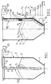
- a container or tank 1 is shown with a wall 2.
- Material 3 is filled in the interior of the container, for example liquid or bulk material, which can be removed via an outlet funnel 4.
- Several practically punctiform pressure sensors 5 are arranged on or in an elongated carrier element 6 of the device 100 at a certain, preferably uniform, vertical distance a from one another.
- the carrier element 6 can have any cross section and is fastened to an upper support 10 and hangs in the container 1 to a substantial depth, namely to the bottom thereof.
- the support element 6 is designed to be tensile in its vertical longitudinal extent, but relatively elastic in the transverse direction (see illustration in FIGS. 3 to 5), so that radial deformations of the support element 6 on the pressure sensors 5 cannot cause any measurement falsifications .
- the carrier element 6 is preferably provided with additional reinforcing inserts 7 (see FIG. 3), so that the pressure sensors 5 always remain in the container 1 at the same height.
- FIG. 2 shows an alternative arrangement of a carrier element 16 for the pressure sensors 5.
- the carrier element 16 is fastened to the inner wall 2 of the container 1, for example welded or glued on.
- One of the pressure sensors 5 approximately halfway inside the carrier element 16 is shown schematically as a partial section.
- the pressure or measured value distribution shown in FIG. 2 on the right as a schematic diagram essentially results, according to which the pressure sensor 5 ′ arranged lowest in the outlet funnel 4 indicates the highest measured value in accordance with the static pressure .
- the pressure decreases continuously in accordance with the altitude of the individual pressure sensors 5.
- measurement values are obtained which, according to the diagram, lie approximately on a straight line as a measurement curve b , the intersection of which with the ordinate axis thus gives the current fill level h 1.
- the measuring curve b and its course, in particular its slope can be precisely defined with the individual measured values, so that a particularly high measuring accuracy and measuring reliability result.
- This evaluation can easily be carried out using known summing or integrating methods with the aid of a likewise known evaluation circuit 50.
- a simple example is the determination of the intersection of the straight line (or other curve) with the ordinate axis. Due to the large number of measured values, an exact continuous level indicator is given as the intersection h 1 between two adjacent pressure sensors.
- the lowest pressure sensor 5 'in the outlet funnel 4 indicates a measured value of, for example, 60 bar.
- the following measured values are then 50 bar, 40 bar, 30 bar, 20 bar and 10 bar, so that straight line b results with a slope of 60 ° to the axis of the abscissa. If, as is indicated by dashed lines, the fill level falls when emptying, the pressure sensor 5 ′′ lying below the section line AA is no longer acted on and all individual measured values are, for example, 10 bar lower. Even then, the curve of the measurement curve must again be shown here as a straight line b ', the intersection of which with the ordinate axis gives the fill level h 2.
- the measurement curves b and b 'etc. thus form a family of curves parallel to one another, so that deviations therefrom can be determined and easily corrected in the evaluation circuit 50.
- the measurement curves b can also represent parabolic sections or other curves.
- the measurement curves are theoretically predetermined by the respective distances between the pressure sensors 5.
- the device is calibrated, for example, by determining the actual curve shape that is representative and characteristic of the later current level measurements (here the straight line b with a gradient of 60 °) and the family of curves, preferably when the container 1 is completely full, since all pressure sensors have 5 measured values deliver and thus the determination of the measurement curve b is carried out most reliably with as many measurement values as possible.
- the level can then be gradually reduced and the corresponding measured values can be determined again.
- the curve shape can also be determined by simulation in an arrangement on a reduced scale.
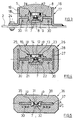
- FIG. 3 shows a cross-sectional view of the device 110 along the cross-sectional line AA of FIG. 2.
- the carrier element 16 consists essentially of the profile rail 17, which is preferably H-shaped and is preferably made of metal and has two side webs 19 and a connecting web 18.
- the carrier element 16 is attached by means of ends 24 of the side webs 19 bent at right angles to the inner wall 2 of the container, for example welded or glued, possibly also screwed on at a few points, as is indicated in the left half of FIG. 3. In this case, a few screw points 24 in the upper region of the container 1 are sufficient, which is generally easily accessible.
- the connecting web 18 the pressure sensors 5 are inserted, which is hermetically sealed from the material 3 with a permanently elastic sheath 8.
- the pressure sensors 5 have a pressure sensor membrane 9 on the side facing away from the pressure p and are connected to the evaluation circuit 50, for example a microprocessor known per se, with cables 30 also running inside the casing 8 of the carrier element 16.
- a pressure sensor which can preferably be used is described, for example, in EP-A-0 394 632 (US Pat. No. 4,984,468).
- the reinforcement inserts 7 can be provided in the region of the side webs 19 and be formed by high-strength sheathing of the cables 30 or, conversely, the reinforcement inserts 7 can be designed as signal-transmitting cables.
- a hat-shaped holder 11 of the pressure sensor 5 is inserted, which in turn receives a sensor body with the pressure sensor membrane 9.
- FIG. 4 shows a cross-sectional view along the line A-A in FIG. 2 of a modified embodiment of a carrier element 26.
- a profile rail 27 is surrounded on all sides by a casing 28.
- This device is particularly suitable for hanging use according to FIG. 1.
- Pressure sensors 25 essentially consist of a hat-shaped, ceramic sensor body 21 with a thin membrane 22, on the back of which known strain gauge measuring strips, preferably in thick-film technology, are provided generate a change in resistance proportional to the pressure p and thus the deformation of the membrane 22 and transmit a corresponding signal via the cable 30 to the evaluation circuit 50.
- the pressure introduction to the membrane 22 takes place via a pressure introduction piston 14, which is guided on its outer circumference with low friction via an annular gap 15 filled with elastomeric material in the holder 23.
- the elastomeric material adheres firmly to the surfaces of the annular gap 15. It is in particular vulcanized and introduced without bubbles, as described in the earlier applications EP-A-0 440 012 (US patent application No. 648,259) and EP-A-0 440 011 ( U.S. Patent Application No. 648,804), which is incorporated by reference.
- EP-A-0 440 012 US patent application No. 648,259
- EP-A-0 440 011 U.S. Patent Application No. 648,804
- FIG. 5 shows a further embodiment of a device 100 or 110 with a carrier element 36 which has a profiled rail 37 and is designed to be relatively flat in the manner of a strip or a belt, so that it is about the axis c is relatively flexible; thus, the carrier element 36 can also be attached to an incompletely flat inner wall 2 of the container without the risk of measurement errors.
- the carrier element 36 can thus even be rolled up and stored and transported as roll goods. 1, the flexible design allows a certain deflection without measurement errors.
- the pressure sensor 35 is designed without an additional pressure introduction piston 14 and pin 12 (FIG. 4). Rather, the elastomeric material of the casing 38 acts directly on the sensor body 31 and the diaphragm 32 when pressure is applied. It should be noted that in all the exemplary embodiments, the pressure sensors 5 etc. are completely encapsulated in the carrier element, so that the material 3 cannot damage them . This results in a very wear-resistant and robust measuring device with high measuring accuracy and measuring reliability.
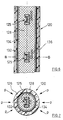
- FIGS. 6 and 7 show a section of an exemplary embodiment of a device 120 according to the invention with pressure sensors 125 arranged at a distance from one another (see FIGS. 3 and 5), which are completely embedded in a body 128 made of elastomeric material with a round, preferably circular or oval cross section .
- the body 128 is surrounded by a jacket 126 which is inelastic in the axial and preferably also in the circumferential direction, but is deformable in the radial direction.
- the Sheath 126 can be, for example, a plastic tube in which axially extending inelastic threads 132, for example made of metal or plastic, are embedded circumferentially. Instead of an axial extension, a spiral course of the threads 132 could also be used.
- the outer surface of the jacket 126 should be wear-resistant in most applications, particularly when level measurement in bunkers.
- the jacket 126 could also be formed by a (metal) fabric.
- the body 128 consists of the most incompressible elastomeric material, for example bubble-free natural or silicone rubber or similar materials, such as are mentioned for example in EP-PS 0 145 001 (US Pat. No. 4,644,805).
- any other pressure sensors can also take their place.
- the body 128 is firmly attached in the jacket 126 to its inner jacket surface in the exemplary embodiment by elastomeric material which is introduced into an annular gap 134.
- a first possibility of producing the body 128 is to arrange the pressure sensors 125 in a tubular shape.
- the pressure sensors 125 there is either at least one line mechanically (and electrically) connecting all the sensors to the evaluation circuit 50 or a type of cable harness 136 if a single line is provided for each pressure sensor.
- the individual pressure sensors 125 or, depending on the rigidity, the line pieces lying between them are provided with corresponding radial spacing elements, as shown in FIG the casting technique is common.
- a closed, straight tube can be used as the shape into which the “armored” pressure sensor / line arrangement is inserted or pulled, or the tube is longitudinally divided, which means the insertion of the pressure sensor / Line arrangement easier.
- a (longitudinally divided) coil similar to a heating or cooling coil can also be used instead of a straight pipe.
- a first possibility is to insert the body 128 loosely into the jacket 126, which is designed as a tube, after the opposite outer or inner jacket surfaces have been treated with a primer or wetting agent.
- the remaining gap is then filled with a relatively liquid curable material, such as silicone or natural rubber or a two-component plastic, which is then vulcanized hot or cold or cured so that the material adheres firmly to the contact surfaces.
- a regular gap can be achieved by pimples or projections or the like cast onto the circumference of the body 128.
- a second possibility of inserting the body 128 into the jacket 126 is to place the latter under considerable pressure, preferably with one end closed, so that it expands radially to such an extent that the body 128 can be inserted. After the pressure has been removed, the jacket 126 lies so firmly against the body 128 that vulcanization or adhesive processes may not be necessary.
- the third possibility of inserting the body 128 into the jacket 126 is to expand the body 128.
- These can be achieved by providing 128 cavities in the body, which are connected to at least one axially continuous line, or by providing only one line running axially through the body 128. After the body 128 has been loosely inserted into the jacket 126, these or the cavities are then filled with a liquid under such pressure that the body 128 expands and lies firmly against the inner jacket surface of the jacket 126.
- the liquid can either be hardenable so that there is a permanent stable arrangement, or the inlet of the line is releasably closed so that the pressure can be reduced if necessary and the body 128 can be pulled out of the jacket 126.
- An alternative embodiment of a sheath could be to wind an inelastic band spirally around body 128.
- the pressure sensors 125 can be equipped with corresponding (ASIC) chips that allow an individual query by the evaluation circuit 50.
- ASIC corresponding
- Such a query can be carried out either via a single (or double) line in series or a bus line with a corresponding byte width in byte-parallel query.
- Each pressure sensor 125 has its own identifier, for example, and the individual pressure sensors 125 are called up one after the other by the microprocessor of the evaluation circuit 50.
- the query can also be forcibly switched from one pressure sensor to the next, so that no identification is required, but only a flip-flop indicating the changing state.
- the interrogation pulse which is converted into direct current and is applied to the resistance measuring bridge of the pressure sensor 125, may be sufficient for the power supply to the individual pressure sensors.
- the resulting analog signal is converted into a digital signal and sent as a response signal to the evaluation circuit 50, e.g. returned via a ring circuit.
- the evaluation circuit 50 then carries out the calculations already described.
- the devices according to the invention allow a much more versatile use: In principle, the device according to the invention can be used wherever pressure changes or the pressure curve are to be determined over a limited, larger distance.
- the compaction of concrete when concreting objects of greater height could also be determined.
- the device according to the invention can thus be inserted transversely into a roadway and it can thus be determined where or when a vehicle is crossing the device.
- the uniform or uneven loading of a base by a larger object for example a pillar, a container, a building or the like, can be determined.
- the invention creates a device which, with relatively inexpensive manufacture and simple construction, has a wide range of possible uses.
Abstract
Description
Die Erfindung betrifft eine Vorrichtung zum Feststellen der Druckverteilung über einer begrenzten Strecke und ein Verfahren zu deren Herstellung mit den Merkmalen des Oberbegriffs des Patentanspruchs 1 bzw. 14, sowie die Verwendung derartiger Vorrichtungen.The invention relates to a device for determining the pressure distribution over a limited distance and a method for its production with the features of the preamble of
In der Technik ergibt sich des öfteren das Problem, die Druckverteilung über eine begrenzte Strecke möglichst genau festzustellen. Eine spezielle Anwendung einer derartigen Messung ist die Füllstandsanzeige in einem flüssiges oder schüttfähiges Gut enthaltenden Behälter.In technology, the problem often arises of determining the pressure distribution over a limited distance as precisely as possible. A special application of such a measurement is the level indicator in a container containing liquid or pourable material.
Die DE-A1-35 33 070 beschreibt eine derartige Füllstandsanzeige, bei der auf der Innenseite in die Behälterwand in vertikalen Abständen Aussparungen eingearbeitet sind, in die mit Dehnungsmeßstreifen versehene Druckmeßdosen eingesetzt sind. Diese Zellen sind mit einer Auswerteschaltung verbunden. Beim Entleeren des Behälters wird eine Zelle nach der anderen vom durch das Füllgut erzeugten Druck entlastet, und das von ihr abgegebene Signal zeigt den augenblicklichen Füllstand an. Die Formung derartiger Aussparungen und die Montage der Druckmeßdosen ist jedoch sehr aufwendig und arbeitsintensiv. Zudem können zwischen den Aussparungen und den Druckmeßdosen Dichtigkeitsprobleme auftreten.DE-A1-35 33 070 describes a fill level indicator of this type, in which recesses are machined on the inside of the container wall at vertical intervals, into which pressure measuring cells provided with strain gauges are inserted. These cells are connected to an evaluation circuit. When the container is emptied, one cell after the other is relieved of the pressure generated by the filling material and the signal emitted by it indicates the current filling level. The formation of such recesses and the assembly of the pressure transducers is very complex and labor intensive. In addition, leakage problems can occur between the recesses and the pressure cells.
Ähnliches gilt für den einzelnen Drucksensor gemäß der EP-A-0 255 084, der in die Öffnung einer Behälterwand plan zu dessen Innenseite eingesetzt ist, so daß der im Behälter herrschende Druck eine Kolbenfläche beaufschlagt und über ein elastomeres Material gleichförmig an einen Drucksensor mit einer Meßmembran weitergeleitet wird. Der Drucksensor ist mit einer Auswerteschaltung verbunden, so daß dessen Meßwerte angezeigt und ausgewertet werden können. Dabei ist ebenfalls nachteilig, daß für den Drucksensor eine Öffnung in der Behälterwand vorgesehen werden muß und insbesondere bei fließfähigem Füllgut in aufwendiger Weise abgedichtet werden muß.The same applies to the individual pressure sensor according to EP-A-0 255 084, which is inserted flat into the opening of a container wall to the inside thereof, so that the pressure prevailing in the container acts on a piston surface and is uniformly applied to a pressure sensor with an elastomeric material Measuring membrane is forwarded. The pressure sensor is connected to an evaluation circuit so that its measured values can be displayed and evaluated. It is also disadvantageous that an opening in the container wall for the pressure sensor must be provided and must be sealed in a complex manner, particularly in the case of flowable contents.
Die DE-A1-36 41 482 beschreibt einen Füllstandssensor unter Verwendung eines Membranschalters mit einem scheibenartigen Gehäuse, das mit der Membran an eine Öffnung des Behälters angesetzt ist. Die DE-C2-33 27 047 beschreibt einen Flüssigkeitsstanddetektor, der an einem Koaxialkabel in dem Behälter aufgehängt ist und temperaturempfindliche Fühler aufweist, die in unterschiedlichen Höhen in dem Behälter hängen. Die DE-C3-31 48 383 befaßt sich mit einer Füllstandsanzeige für einen Kraftfahrzeug-Kraftstoffbehälter mit einer Sonde, auf der in zum Teil unterschiedlichen Abständen einzelne Kaltleiter angeordnet sind. Die DD-A1-247 971 befaßt sich mit einer Füllstandsanzeige, bei der ein piezoresistiver Druckwandler an einer Leitung hängend in bestimmter Höhe in die Flüssigkeit eingetaucht ist.DE-A1-36 41 482 describes a level sensor using a membrane switch with a disk-like housing which is attached to an opening of the container with the membrane. DE-C2-33 27 047 describes a liquid level detector which is suspended from a coaxial cable in the container and has temperature-sensitive sensors which hang at different heights in the container. DE-C3-31 48 383 is concerned with a level indicator for a motor vehicle fuel tank with a probe on which individual PTC thermistors are arranged at different intervals. The DD-A1-247 971 is concerned with a level indicator in which a piezoresistive pressure transducer hanging from a line is immersed in the liquid at a certain height.
Der Erfindung liegt die Aufgabe zugrunde, eine Vorrichtung zum Feststellen der Druckverteilung über einer begrenzten Strecke anzugeben, die einfach und robust aufgebaut ist, kostengünstig herstellbar ist und vielseitig verwendet werden kann. Ferner sollen ein einfaches und kostengünstiges Verfahren zum Herstellen derartiger Vorrichtungen und besonders bevorzugte Verwendungen derartiger Vorrichtungen angegeben werden.The invention has for its object to provide a device for determining the pressure distribution over a limited distance, which is simple and robust, is inexpensive to manufacture and can be used in a variety of ways. Furthermore, a simple and inexpensive method for producing such devices and particularly preferred uses of such devices are to be specified.
Gemäß der Erfindung wird diese Aufgabe gelöst durch eine Vorrichtung mit den Merkmalen des Patentanspruchs 1 bzw. ein Verfahren mit den Merkmalen des Patentanspruchs 14 und Verwendungen gemäß Patentanspruch 15.According to the invention, this object is achieved by a device with the features of
Bevorzugte Weiterbildungen der erfindungsgemäßen Vorrichtung bzw. des erfindungsgemäßen Verfahrens sind in den abhängigen Ansprüchen gekennzeichnet.Preferred developments of the device according to the invention and of the method according to the invention are characterized in the dependent claims.
Die Erfindung wird nachfolgend anhand mehrerer in der Zeichnung dargestellten Ausführungsbeispiele näher erläutert. Es zeigen:
- Fig. 1
- einen Vertikalschnitt durch einen Behälter mit einer ersten Ausführung der Vorrichtung zum Messen des Füllstandes;
- Fig. 2
- einen Vertikalschnitt durch den Behälter mit einer weiteren Ausführungsform der Füllstand-Meßvorrichtung mit zugehörigem schematischem Meßwert-Diagramm;
- Fig. 3
- einen Querschnitt entlang der Linie A-A in Fig. 2 durch das Trägerelement;
- Fig. 4
- eine abgewandelte Ausführungsform gemäß Fig. 3;
- Fig. 5
- eine weitere Abwandlung;
- Fig. 6
- einen Axial-Längsschnitt durch einen Abschnitt eines weiteren Ausführungsbeispiels der erfindungsgemäßen Vorrichtung; und
- Fig. 7
- einen Querschnitt längs der Linie B-B in Fig. 6.
- Fig. 1
- a vertical section through a container with a first embodiment of the device for measuring the level;
- Fig. 2
- a vertical section through the container with a further embodiment of the level measuring device with associated schematic measured value diagram;
- Fig. 3
- a cross section along the line AA in Figure 2 by the support member.
- Fig. 4
- a modified embodiment of FIG. 3;
- Fig. 5
- another variation;
- Fig. 6
- an axial longitudinal section through a section of a further embodiment of the device according to the invention; and
- Fig. 7
- 6 shows a cross section along the line BB in FIG. 6.
In Fig. 1 ist ein Behälter oder Tank 1 mit einer Wand 2 dargestellt. Im Innern des Behälters ist Material 3 eingefüllt, beispielsweise Flüssigkeit oder Schüttgut, das über einen Auslauftrichter 4 entnommen werden kann. Mehrere praktisch punktförmige Drucksensoren 5 sind an oder in einem länglichen Trägerelement 6 der Vorrichtung 100 in einem bestimmten, vorzugsweise gleichmäßigen vertikalen Abstand a zueinander angeordnet. Das Trägerelement 6 kann einen beliebigen Querschnitt aufweisen und ist an einer oberen Abstützung 10 befestigt und hängt in den Behälter 1 bis zu einer wesentlichen Tiefe, nämlich bis zu dessen Boden.In Fig. 1, a container or
Um Meßfehler durch Schüttgutbewegungen auszuschließen, ist das Trägerelement 6 zugfest in seiner vertikalen Längserstreckung, jedoch in Querrichtung dazu (vgl. Darstellung in den Figuren 3 bis 5) relativ elastisch ausgebildet, so daß radiale Verformungen des Trägerelementes 6 an den Drucksensoren 5 keine Meßwertverfälschungen hervorrufen können. In vertikaler Längsrichtung ist das Trägerelement 6 bevorzugt mit zusätzlichen Verstärkungseinlagen 7 (vgl. Fig. 3) versehen, so daß die Drucksensoren 5 immer auf der gleichen Höhenlage im Behälter 1 verbleiben.In order to rule out measurement errors due to bulk material movements, the
In Fig. 2 ist eine alternative Anordnung eines Trägerelements 16 für die Drucksensoren 5 dargestellt. Hierbei ist das Trägerelement 16 an der Innenwand 2 des Behälters 1 befestigt, beispielsweise aufgeschweißt oder aufgeklebt. Einer der Drucksensoren 5 etwa auf halber Höhe innerhalb des Trägerelementes 16 ist als Teilschnitt schematisch gezeigt. Bei dem dargestellten Füllstand des Materials 3 innerhalb des Behälters 1 ergibt sich im wesentlichen die in Fig. 2 rechts als schematisches Diagramm dargestellte Druck- bzw. Meßwertverteilung, wonach der im Auslauftrichter 4 am tiefsten angeordnete Drucksensor 5' entsprechend dem statischen Druck den höchsten Meßwert anzeigt. Der Druck nimmt entsprechend der Höhenlage der einzelnen Drucksensoren 5 kontinuierlich ab. Bei gleichmäßiger Auslegung und gleichmäßigem Abstand a der Drucksensoren 5 ergeben sich Meßwerte, die entsprechend dem Diagramm etwa auf einer Geraden als Meßkurve b liegen, deren Schnittpunkt mit der Ordinatenachse damit den aktuellen Füllstand h₁ ergibt.2 shows an alternative arrangement of a
Sollte einer der Drucksensoren 5 im Laufe der Zeit defekt sein, so würde deren Meßwert weit unterhalb oder oberhalb der als Geraden dargestellten Meßkurve b liegen, so daß dieser Drucksensor erkannt werden kann und für das Gesamtmeßergebnis nicht berücksichtigt wird. Durch die Vielzahl der Meßstellen kann mit den einzelnen Meßwerten die Meßkurve b und deren Verlauf, insbesondere deren Steigung genau festgelegt werden, so daß sich eine besonders hohe Meßgenauigkeit und Meßsicherheit ergibt. Diese Auswertung läßt sich mit bekannten Summier- bzw. Integriermethoden mit Hilfe einer ebenfalls bekannten Auswerteschaltung 50 ohne weiteres durchführen. Ein einfaches Beispiel ist die Bestimmung des Schnittpunkts der Geraden (oder anderen Kurve) mit der Ordinatenachse. Aufgrund der Vielzahl der Meßwerte ist eine exakte kontinuierliche Füllstandsanzeige als Schnittpunkt h₁ zwischen zwei benachbarten Drucksensoren gegeben.Should one of the
Es sei hier angenommen, daß der unterste Drucksensor 5' im Auslauftrichter 4 einen Meßwert von z.B. 60 bar anzeigt. Die nach oben folgenden Meßwerte seien dann 50 bar, 40 bar, 30 bar, 20 bar und 10 bar, so daß sich die Gerade b mit einer Steigung von 60° zur Achse der Abszisse hin ergibt. Fällt nun beim Entleeren der Füllstand, wie dies gestrichelt angedeutet ist, so wird der unter der Schnittlinie A-A liegende Drucksensor 5'' nicht mehr beaufschlagt und alle einzelnen Meßwerte liegen z.B. um 10 bar tiefer. Auch dann muß sich wiederum der Kurvenverlauf der Meßkurve hier als Gerade b' zeigen, deren Schnittpunkt mit der Ordinatenachse den Füllstand h₂ ergibt.It is assumed here that the lowest pressure sensor 5 'in the
Die Meßkurven b und b' usw. bilden somit eine zueinander parallele Kurvenschar, so daß Abweichungen hiervon in der Auswerteschaltung 50 feststellbar und einfach korrigierbar sind.The measurement curves b and b 'etc. thus form a family of curves parallel to one another, so that deviations therefrom can be determined and easily corrected in the
Selbstverständlich können die Meßkurven b abhängig von der Behälterform und der Anordnung der Drucksensoren auch Parabelabschnitte oder andere Kurven darstellen. Die Meßkurven sind theoretisch durch die jeweiligen Abstände der Drucksensoren 5 zueinander vorgegeben. In der Praxis erfolgt die Kalibrierung der Vorrichtung z.B. durch Feststellung der für die späteren laufenden Füllstandsmessungen repräsentativen und charakteristischen tatsächlichen Kurvenform (hier der Geraden b mit der Steigung 60°) und der Kurvenschar dabei bevorzugt bei vollständig gefülltem Behälter 1, da hierbei alle Drucksensoren 5 Meßwerte liefern und somit die Festlegung der Meßkurve b mit möglichst vielen Meßwerten am zuverlässigsten erfolgt. Der Füllstand kann dann nach und nach verringert und die entsprechenden Meßwerte können wiederum bestimmt werden. Die Kurvenform kann jedoch neben dieser empirischen Ermittlung auch durch Simulation in einer Anordnung mit verkleinertem Maßstab festgelegt werden.Of course, depending on the shape of the container and the arrangement of the pressure sensors, the measurement curves b can also represent parabolic sections or other curves. The measurement curves are theoretically predetermined by the respective distances between the
Es sei darauf hingewiesen, daß für eine grobe Füllstandsmessung es auch ausreicht, nur die jeweils mit Druck beaufschlagten Drucksensoren 5, jedoch nicht deren exakten Meßwert zu erfassen, so daß der Abstand a zwischen den einzelnen Drucksensoren 5 ein Maß für die erreichbare Meßgenauigkeit hinsichtlich des Füllstandes ergibt. In dem in Fig. 2 dargestellten Beispiel ist der Drucksensor 5, durch den die Querschnittslinie A-A verläuft noch nicht vom Material 3 beaufschlagt, während der darunterliegende Drucksensor 5'' bereits beaufschlagt ist. Hierdurch kann der Füllstand als zwischen diesen beiden benachbarten Drucksensoren liegend angegeben werden, da deren Höhenlage durch die ortsfeste Anordnung am Trägerelement 16 bekannt ist.It should be pointed out that for a rough level measurement, it is also sufficient to detect only the
In Fig. 3 ist eine Querschnittsansicht der Vorrichtung 110 entlang der Querschnittslinie A-A der Fig. 2 dargestellt. Das Trägerelement 16 besteht im wesentlichen aus der Profilschiene 17, die bevorzugt H-förmig ausgebildet und bevorzugt aus Metall ist und zwei Seitenstege 19 und einen Verbindungssteg 18 aufweist. Das Trägerelement 16 ist mittels rechtwinklig abgebogener Enden 24 der Seitenstege 19 an der Behälterinnenwand 2 angebracht, etwa angeschweißt oder angeklebt, ggf. auch an wenigen Stellen angeschraubt, wie dies in der linken Hälfte von Fig. 3 angedeutet ist. Hierbei reichen einige Schraubstellen 24 im oberen Bereich des Behälters 1 aus, der im allgemeinen leicht zugänglich ist. In den Verbindungssteg 18 sind die Drucksensoren 5 eingesetzt, der gegenüber dem Material 3 mit einer dauerelastischen Ummantelung 8 hermetisch abgedichtet ist. Die Drucksensoren 5 weisen in bevorzugter Ausführung an der vom Druck p abgewandten Seite eine Drucksensormembran 9 auf und sind mit ebenfalls innerhalb der Ummantelung 8 des Trägerelementes 16 verlaufenden Kabeln 30 mit der nicht näher dargestellten Auswerteschaltung 50, z.B. einem an sich bekannten Mikroprozessor verbunden. Ein bevorzugt einsetzbarer Drucksensor ist beispielsweise beschrieben in der EP-A-0 394 632 (US-Patent Nr. 4,984,468). Die Verstärkungseinlagen 7 können im Bereich der Seitenstege 19 vorgesehen sein und durch hochfeste Ummantelungen der Kabel 30 gebildet sein bzw. umgekehrt die Verstärkungseinlagen 7 als signalübertragende Kabel ausgestaltet sein.FIG. 3 shows a cross-sectional view of the
In dem Verbindungssteg 18 ist eine hutförmige Halterung 11 des Drucksensors 5 eingesetzt, die wiederum einen Sensorkörper mit der Drucksensormembran 9 aufnimmt.In the connecting web 18, a hat-shaped
In Fig. 4 ist eine Querschnittsansicht entlang der Linie A-A in Fig. 2 einer abgewandelten Ausführung eines Trägerelementes 26 dargestellt. Hierbei ist eine Profilschiene 27 allseitig von einer Ummantelung 28 umgeben. Diese Vorrichtung eignet sich insbesondere für den hängenden Einsatz gemäß Fig. 1. Drucksensoren 25 bestehen im wesentlichen aus einem hutförmigen, keramischen Sensorkörper 21, mit einer dünnen Membran 22, auf deren Rückseite an sich bekannte DMS-Meßstreifen, bevorzugt in Dickschichttechnik vorgesehen sind, die eine dem Druck p und damit der Verformung der Membran 22 proportionale Widerstandsänderung erzeugen und ein entsprechendes Signal über die Kabel 30 an die Auswerteschaltung 50 weitergeben. Die Druckeinleitung zur Membran 22 erfolgt über einen Druckeinleitungkolben 14, der an seinem Außenumfang über einen mit elastomerem Material gefüllten Ringspalt 15 in der Halterung 23 reibungsarm geführt ist. Das elastomere Material haftet fest an den Flächen des Ringspalts 15. Es ist insbesondere vulkanisiert und blasenfrei eingebracht, wie dies in den älteren Anmeldungen EP-A-0 440 012 (US-Patentanmeldung Nr. 648,259) und EP-A-0 440 011 (US-Patentanmeldung Nr. 648,804) beschrieben wird, auf die vollinhaltlich Bezug genommen wird. Hierdurch wird bereits eine vergleichsmäßigte Druckeinleitung bewirkt, wobei durch einen weiteren Ringspalt 13, der ebenfalls wieder mit dem oben beschriebenen Elastomer gefüllt ist, eine weitere Vergleichmäßigung erreicht wird. In den Ringspalt 13 ist ein kolbenartiger Zapfen 12 der Druckeinleitungsplatte 14 eingesetzt, der über das Elastomer an seinem Bodenbereich auf die Membran 22 wirkt.FIG. 4 shows a cross-sectional view along the line A-A in FIG. 2 of a modified embodiment of a
In Fig. 5 ist eine weitere Ausführungsform einer Vorrichtung 100 oder 110 dargestellt mit einem Trägerelement 36, das eine Profilschiene 37 aufweist und in Art einer Leiste oder eines Gurtes relativ flach ausgebildet ist, so daß diese um die Achse c relativ biegeweich ist; somit kann das Trägerelement 36 ohne die Gefahr von Meßfehlern auch an einer nicht vollständig ebenen Behälterinnenwand 2 angebracht werden. Damit kann das Trägerelement 36 sogar aufgerollt und als Rollenware aufbewahrt und transportiert werden. Bei der freihängenden Ausführung gemäß Fig. 1 ermöglicht die biegeweiche Ausführung eine gewisse Auslenkung ohne Meßfehler.5 shows a further embodiment of a
Im Gegensatz zu den beiden vorhergehenden Ausführungsformen ist hier der Drucksensor 35 ohne zusätzlichen Druckeinleitungskolben 14 und Zapfen 12 (Fig. 4) ausgestaltet. Vielmehr wirkt hier das elastomere Material der Ummantelung 38 bei Druckbeaufschlagung direkt auf den Sensorkörper 31 und die Membran 32. Es sei darauf hingewiesen, daß bei allen Ausführungsbeispielen die Drucksensoren 5 etc. vollständig im Trägerelement eingekapselt sind, so daß das Material 3 diese nicht beschädigen kann. Somit ergibt sich eine sehr verschleißfeste und robuste Meßvorrichtung mit hoher Meßgenauigkeit und Meßsicherheit.In contrast to the two previous embodiments, here the
Die Figuren 6 und 7 zeigen einen Abschnitt eines Ausführungsbeispiels einer erfindungsgemäßen Vorrichtung 120 mit in Abstand zueinander angeordneten Drucksensoren 125 (vgl. Fig. 3 und 5), die in einem Körper 128 aus elastomerem Material mit rundem, vorzugsweise kreisförmigem oder ovalem Querschnitt vollständig eingebettet sind.FIGS. 6 and 7 show a section of an exemplary embodiment of a
Bezüglich des grundsätzlichen Aufbaus der Vorrichtung 120, der Ausgestaltung und Anordnung sowie Beschaltung der Drucksensoren und des Einsatzes der erfindungsgemäßen Vorrichtung wird auf die Beschreibung der vorhergehenden Ausführungsbeispiele verwiesen. Die vorliegende Beschreibung beschränkt sich deshalb auf die gegenüber diesen Ausführungsbeispielen vorgenommenen Modifikationen und Verbesserungen.With regard to the basic structure of the
Der Körper 128 ist von einem Mantel 126 umgeben, der in axialer und vorzugsweise auch in Umfangsrichtung unelastisch, in radialer Richtung jedoch verformbar ausgebildet ist. Der Mantel 126 kann beispielsweise ein Kunststoffschlauch sein, in dem axial verlaufende unelastische Fäden 132 beispielsweise aus Metall oder Kunststoff umfangsmäßig verteilt eingebettet sind. Anstelle einer axialen Erstreckung käme auch ein spiralförmig angeordneter Verlauf der Fäden 132 in Frage. Die äußere Oberfläche des Mantels 126 sollte bei den meisten Anwendungen verschleißfest sein, insbesondere bei der Füllstandsmessung in Bunkern. Der Mantel 126 könnte auch durch ein (Metall-)Gewebe gebildet sein.The
Der Körper 128 besteht aus möglichst inkompressiblem elastomerem Material, beispielsweise blasenfreiem Natur- oder Silikonkautschuk oder ähnlichen Materialien, wie sie beispielsweise in der EP-PS 0 145 001 (US-Patent Nr. 4,644,805) für ähnliche Zwecke genannt sind.The
Obwohl als Drucksensoren 125 bevorzugt diejenigen gemäß den vorherigen Ausführungsbeispielen eingesetzt werden, können auch beliebige andere Drucksensoren an deren Stelle treten.Although those according to the previous exemplary embodiments are preferably used as
Der Körper 128 ist im Mantel 126 an dessen Innenmantelfläche beim Ausführungsbeispiel durch elastomeres Material festhaftend befestigt, das in einem Ringspalt 134 eingebracht ist.The
Nachstehend werden verschiedene Alternativen der Herstellung des Körpers 128 bzw. dessen Einfügen in den Mantel 126 als beispielsweise Möglichkeiten beschrieben:Various alternatives for producing the
Eine erste Möglichkeit der Herstellung des Körpers 128 besteht darin, in einer rohrartigen Form die Drucksensoren 125 anzuordnen. Abhängig von der nachstehend noch im einzelnen zu beschreibenden Beschaltung ist entweder mindestens eine alle Sensoren mit der Auswerteschaltung 50 mechanisch (und elektrisch) verbindende Leitung oder aber eine Art Kabelbaum 136 vorhanden, falls pro Drucksensor je eine Einzelleitung vorgesehen ist. Die einzelnen Drucksensoren 125 oder -je nach Steifigkeit- die dazwischen liegenden Leitungsstücke werden mit entsprechenden radialen Abstandselementen versehen, wie dies in der Gießtechnik üblich ist. Je nach Länge des herzustellenden Körpers 128 und dessen Durchmesser kann entweder ein geschlossenes gerades Rohr als Form verwendet werden, in das die "armierte" Drucksensor-/Leitungsanordnung eingeschoben bzw. eingezogen wird, oder aber das Rohr ist längsgeteilt, was das Einsetzen der Drucksensor-/Leitungsanordnung erleichtert. Für große Längen kann anstelle eines geraden Rohres auch eine (längsgeteilte) Rohrschlange ähnlich einer Heiz- oder Kühlschlange verwendet werden.A first possibility of producing the
Auch ein Strangpressen des Körpers 128 ist in Betracht zu ziehen.Extrusion of the
Für das Einbringen des Körpers 128 in den Mantel 126 gibt es verschiedene Möglichkeiten:
Eine erste Möglichkeit besteht darin, den Körper 128 lose in den als Schlauch ausgebildeten Mantel 126 einzusetzen, nachdem die gegenüberliegenden Außen- bzw. Innenmantelflächen mit einem Primer oder Benetzungsmittel behandelt wurden. Der verbleibende Spalt wird dann mit einem verhältnismäßig flüssigen aushärtbaren Stoff, etwa Silikon- oder Naturkautschuk oder einem Zweikomponenten-Kunststoff gefüllt, der dann heiß oder kalt vulkanisiert bzw. ausgehärtet wird, so daß sich ein festes Haften des Materials an den Kontaktflächen ergibt. Ein regelmäßiger Spalt kann durch am Umfang des Körpers 128 angegossene Noppen oder Vorsprünge oder dgl. erzielt werden.There are various options for inserting the
A first possibility is to insert the
Eine zweite Möglichkeit des Einbringens des Körpers 128 in den Mantel 126 besteht darin, letzteren vorzugsweise bei verschlossenem einen Ende unter erheblichen Druck zu setzen, so daß er sich radial so weit ausdehnt, daß der Körper 128 eingeführt werden kann. Nach Wegnehmen des Druckes legt sich der Mantel 126 so fest am Körper 128 an, daß ggf. Vulkanisations- oder Klebevorgänge nicht erforderlich sind.A second possibility of inserting the
Als dritte Möglichkeit des Einbringens des Körpers 128 in den Mantel 126 kommt eine Ausdehnung des Körpers 128 in Frage. Diese kann dadurch erreicht werden, daß im Körper 128 Hohlräume vorgesehen sind, die mit mindestens einer axial durchgehenden Leitung verbunden sind, oder daß überhaupt nur eine axial durch den Körper 128 verlaufende Leitung vorgesehen ist. Diese bzw. die Hohlräume werden dann nach losem Einsetzen des Körpers 128 in den Mantel 126 mit einer Flüssigkeit unter derartigem Druck gefüllt, daß sich der Körper 128 ausweitet und sich fest an die Innenmantelfläche des Mantels 126 anlegt. Die Flüssigkeit kann entweder aushärtbar sein, so daß sich eine permanent stabile Anordnung ergibt, oder der Eingang der Leitung wird lösbar verschlossen, so daß der Druck bei Bedarf verringert und der Körper 128 aus dem Mantel 126 herausgezogen werden kann.The third possibility of inserting the
Als weitere Möglichkeit wird das an sich bekannte Extrudierverfahren genannt.The extrusion process known per se is mentioned as a further possibility.
Eine alternative Ausführungsform einer Ummantelung könnte darin bestehen, daß ein unelastisches Band spiralförmig um den Körper 128 gewickelt wird.An alternative embodiment of a sheath could be to wind an inelastic band spirally around
Es sollen nun weitere Einzelheiten der elektrischen Beschaltung der Drucksensoren angegeben werden.Further details of the electrical wiring of the pressure sensors are now to be given.
Hierzu können die Drucksensoren 125 mit entsprechenden (ASIC)-Chips bestückt sein, die eine individuelle Abfrage durch die Auswerteschaltung 50 erlauben. Eine derartige Abfrage kann entweder über eine Einzel-(oder Doppel-)Leitung seriell oder eine Busleitung mit entsprechender Byte-Breite in byte-paralleler Abfrage erfolgen. Jeder Drucksensor 125 besitzt beispielsweise eine eigene Kennung und die einzelnen Drucksensoren 125 werden vom Mikroprozessor der Auswerteschaltung 50 nacheinander aufgerufen. Alternativ dazu kann die Abfrage aber auch von einem Drucksensor zum nächsten zwangsweise weitergeschaltet werden, so daß keine Kennung erforderlich ist, sondern lediglich eine den wechselnden Zustand angebende Kippstufe.For this purpose, the
Für die Leistungszufuhr zu den einzelnen Drucksensoren kann der Abfrageimpuls ausreichen, der in Gleichstrom umgewandelt an die Widerstandsmeßbrücke des Drucksensors 125 gelegt wird. Das sich ergebende Analogsinal wird in ein Digitalsignal umgewandelt und als Antwortsignal an die Auswerteschaltung 50, z.B. über eine Ringschaltung zurückgegeben.The interrogation pulse, which is converted into direct current and is applied to the resistance measuring bridge of the
Die Auswerteschaltung 50 nimmt dann die bereits beschriebenen Berechnungen vor.The
Bisher wurde als Anwendung der erfindungsgemäßen Vorrichtung das Messen des Füllstands eines Behälters oder anderen Containers angegeben.So far, measuring the level of a container or other container has been specified as an application of the device according to the invention.
Die erfindungsgemäßen Vorrichtungen erlauben jedoch einen wesentlich vielseitigeren Einsatz:
Im Prinzip ist die erfindungsgemäße Vorrichtung überall dort einsetzbar, wo Druckänderungen bzw. der Druckverlauf über einer begrenzten größeren Strecke festgestellt werden soll.However, the devices according to the invention allow a much more versatile use:
In principle, the device according to the invention can be used wherever pressure changes or the pressure curve are to be determined over a limited, larger distance.
Als weitere Beispiele für einen vertikalen Einsatz sei auf das Eintauchen in Flüssigkeiten verwiesen, in denen die Auswirkungen von Strömungen, Druckwellen, Explosionen etc. über der Höhe festgestellt werden sollen.As further examples of vertical use, reference is made to immersion in liquids, in which the effects of currents, pressure waves, explosions, etc. are to be determined above the level.
Ferner ließe sich beispielsweise auch die Verdichtung von Beton beim Betonieren von Objekten größerer Höhe feststellen.Furthermore, for example, the compaction of concrete when concreting objects of greater height could also be determined.
Aber auch nicht-vertikale Anwendungen kommen in Frage.But non-vertical applications are also possible.
So läßt sich die erfindungsgemäße Vorrichtung quer in eine Fahrbahn einfügen und es kann damit festgestellt werden, wo oder auch wann ein Fahrzeug die Vorrichtung überquert.The device according to the invention can thus be inserted transversely into a roadway and it can thus be determined where or when a vehicle is crossing the device.
Ferner kann die gleichmäßige bzw. ungleichmäßige Belastung einer Unterlage durch ein größeres Objekt, beispielsweise einen Pfeiler, einen Container, ein Gebäude oder dgl. festgestellt werden.Furthermore, the uniform or uneven loading of a base by a larger object, for example a pillar, a container, a building or the like, can be determined.
Aufgrund der kabelförmigen Ausbildung ist auch die Möglichkeit gegeben, die erfindungsgemäße Vorrichtung wie ein Kabel in das Erdreich einzuschießen.Because of the cable-shaped design, there is also the possibility of shooting the device according to the invention into the ground like a cable.
Insgesamt zeigt sich somit, daß durch die Erfindung eine Vorrichtung geschaffen wird, die bei verhältnismäßig kostengünstiger Herstellung und einfachem Aufbau vielfältige Anwendungsmöglichkeiten besitzt.Overall, it can thus be seen that the invention creates a device which, with relatively inexpensive manufacture and simple construction, has a wide range of possible uses.
Claims (15)
dadurch gekennzeichnet, daß
die Drucksensoren (5;25;35;125) linear auf/in einem länglichen Trägerelement (6;16;26;36) angeordnet sind.Device for determining the pressure distribution over a limited distance, in particular for indicating the fill level in containers (1), with a plurality of pressure sensors (5; 25; 35; 125) arranged at essentially the same distance from one another, which are connected to an evaluation circuit (50),
characterized in that
the pressure sensors (5; 25; 35; 125) are arranged linearly on / in an elongated carrier element (6; 16; 26; 36).
Applications Claiming Priority (4)
| Application Number | Priority Date | Filing Date | Title |
|---|---|---|---|
| DE19914104177 DE4104177A1 (en) | 1991-02-12 | 1991-02-12 | Level measurement of material in container - with pressure measurement cells at uniform vertical intervals on common carrier attached to container wall or suspended from support |
| DE4104177 | 1991-02-12 | ||
| DE4115292A DE4115292A1 (en) | 1991-02-12 | 1991-05-10 | LEVEL MEASURING DEVICE WITH PRESSURE MEASURING DEVICE |
| DE4115292 | 1991-05-10 |
Publications (2)
| Publication Number | Publication Date |
|---|---|
| EP0499202A2 true EP0499202A2 (en) | 1992-08-19 |
| EP0499202A3 EP0499202A3 (en) | 1993-05-05 |
Family
ID=25900949
Family Applications (1)
| Application Number | Title | Priority Date | Filing Date |
|---|---|---|---|
| EP19920102255 Withdrawn EP0499202A3 (en) | 1991-02-12 | 1992-02-11 | Device to determine the pressure distribution in a limited path and method of its fabrication |
Country Status (4)
| Country | Link |
|---|---|
| US (1) | US5325716A (en) |
| EP (1) | EP0499202A3 (en) |
| CA (1) | CA2060705A1 (en) |
| DE (1) | DE4115292A1 (en) |
Families Citing this family (21)
| Publication number | Priority date | Publication date | Assignee | Title |
|---|---|---|---|---|
| US5601205A (en) * | 1996-04-01 | 1997-02-11 | Ford Motor Company | Fuel tank assembly |
| ATE412880T1 (en) * | 1997-11-20 | 2008-11-15 | Innovative Measurement Methods | MULTIPLE ARRANGEMENT FOR FILL LEVEL MEASURING FUEL STORAGE TANKS |
| JP4055839B2 (en) * | 2000-04-27 | 2008-03-05 | 東京エレクトロン株式会社 | Liquid level detection apparatus and method |
| FR2840065B1 (en) * | 2002-05-24 | 2004-09-03 | Serpe Iesm Soc D Etudes Et De | DEVICE FOR MEASURING THE FILLING STATE OF A SILO |
| FR2840066B1 (en) * | 2002-05-24 | 2004-08-06 | Serpe Iesm Soc D Etudes Et De | SILO FILLING STATE MEASURING DEVICE |
| EP1489392A1 (en) * | 2003-06-16 | 2004-12-22 | Siemens Aktiengesellschaft | A method for manufacturing an electronic arrangement and an electronic circuit arrangement |
| JP4049102B2 (en) * | 2004-01-21 | 2008-02-20 | 株式会社デンソー | Pressure sensor |
| WO2009041579A1 (en) * | 2007-09-27 | 2009-04-02 | Nippon Steel Engineering Co., Ltd. | Bubbling tower hydrocarbon reactor and method of detecting slurry surface level |
| NO327870B1 (en) * | 2007-12-19 | 2009-10-12 | Norsk Hydro As | Method and equipment for determining interface between two or more fluid phases |
| US8181515B2 (en) * | 2008-11-18 | 2012-05-22 | Colin Stephens | Fluid level indicator strip |
| RU2643213C2 (en) | 2013-06-13 | 2018-01-31 | Лидинг Эдж Индастриз, Инк. | System of sensor of filling grain transportation trailer |
| US9140595B2 (en) | 2013-08-21 | 2015-09-22 | Conecraft, Inc. | Fluid level indicator for a lined bulk material container |
| US20150096804A1 (en) * | 2013-10-04 | 2015-04-09 | Ultra Analytical Group, LLC | Apparatus, System and Method for Measuring the Properties of a Corrosive Liquid |
| US20150096369A1 (en) * | 2013-10-04 | 2015-04-09 | Ultra Analytical Group, LLC | Apparatus, System and Method for Measuring the Properties of a Corrosive Liquid |
| RU2559979C1 (en) * | 2014-07-08 | 2015-08-20 | Ильдар Зафирович Денисламов | Method of liquid level determination in well |
| US20160054349A1 (en) * | 2014-08-25 | 2016-02-25 | Genmark Automation, Inc. | Whisker sensor device, method or manufacturing the same, and computer method, system and software for the same |
| WO2017048248A1 (en) * | 2015-09-16 | 2017-03-23 | Halliburton Energy Services, Inc. | Method and apparatus for measuring characteristics of fluid in a reservoir |
| US10231381B2 (en) | 2015-10-23 | 2019-03-19 | Cnh Industrial America Llc | Pneumatic grain level sensor and method therefore |
| CN112739993B (en) * | 2018-10-01 | 2023-12-05 | 庄信万丰股份有限公司 | Device for determining the vertical level or density distribution of a fluid column |
| MX2021008733A (en) * | 2019-04-05 | 2021-08-24 | Hewlett Packard Development Co | Fluid property sensor. |
| CN113970401B (en) * | 2021-12-22 | 2022-04-01 | 季华实验室 | Pipeline pressure sensor |
Citations (3)
| Publication number | Priority date | Publication date | Assignee | Title |
|---|---|---|---|---|
| JPS58127129A (en) * | 1982-01-23 | 1983-07-28 | Ohkura Electric Co Ltd | Precision measuring device for high liquid level |
| US4753105A (en) * | 1987-01-22 | 1988-06-28 | Pressure Systems Incorporated | Electronic pressure scanner |
| GB2228325A (en) * | 1989-02-21 | 1990-08-22 | Sidney William Simpson | Level detector for particulate material |
Family Cites Families (14)
| Publication number | Priority date | Publication date | Assignee | Title |
|---|---|---|---|---|
| GB865909A (en) * | 1957-10-03 | 1961-04-19 | Dobbie Mcinnes Ltd | Improvements in or relating to indicating apparatus for measuring the pressure head or level of liquid relative to a datum level |
| US3153342A (en) * | 1961-09-07 | 1964-10-20 | Norton T Pierce | Fluent material level measuring apparatus and method of manufacturing the same |
| US3290938A (en) * | 1965-05-13 | 1966-12-13 | Ralph R Miller | Pneumatic displacement level indicator for storage bin |
| US3583221A (en) * | 1969-04-07 | 1971-06-08 | Metritape | Dry bulk level sensing system |
| US3550447A (en) * | 1969-04-23 | 1970-12-29 | John I Beresic | Hopper material supply indicator |
| US3792407A (en) * | 1971-09-15 | 1974-02-12 | Metritape | Channel mounted level sensor |
| SU392345A1 (en) * | 1971-11-01 | 1973-07-27 | ALL-UNION YAENTENTIO-TEKHEYCHESH | |
| US4007636A (en) * | 1973-08-30 | 1977-02-15 | Mine Safety Appliances Company | Liquid metal level indicator |
| DE3240107A1 (en) * | 1982-10-29 | 1984-05-03 | Heinz 4354 Datteln Wolf | Device for monitoring the filling level of a pourable or liquid material in a tank |
| DE3344901A1 (en) * | 1983-12-12 | 1985-06-13 | Pfister Gmbh, 8900 Augsburg | FORCE MEASUREMENT CELL |
| DE3502275A1 (en) * | 1985-01-24 | 1986-07-24 | Wabco Westinghouse Fahrzeugbremsen GmbH, 3000 Hannover | Force sensor |
| US4631374A (en) * | 1985-12-06 | 1986-12-23 | Dwyer Instruments, Inc. | Diaphragm operated switch type bin level sensor |
| US4799381A (en) * | 1988-02-21 | 1989-01-24 | Cmi International, Inc. | Vehicle road sensor |
| US4890492A (en) * | 1988-09-06 | 1990-01-02 | Emhart Industries, Inc. | Differential pressure level sensor with temperature sensing elements |
-
1991
- 1991-05-10 DE DE4115292A patent/DE4115292A1/en not_active Withdrawn
-
1992
- 1992-02-05 CA CA002060705A patent/CA2060705A1/en not_active Abandoned
- 1992-02-07 US US07/832,860 patent/US5325716A/en not_active Expired - Fee Related
- 1992-02-11 EP EP19920102255 patent/EP0499202A3/en not_active Withdrawn
Patent Citations (3)
| Publication number | Priority date | Publication date | Assignee | Title |
|---|---|---|---|---|
| JPS58127129A (en) * | 1982-01-23 | 1983-07-28 | Ohkura Electric Co Ltd | Precision measuring device for high liquid level |
| US4753105A (en) * | 1987-01-22 | 1988-06-28 | Pressure Systems Incorporated | Electronic pressure scanner |
| GB2228325A (en) * | 1989-02-21 | 1990-08-22 | Sidney William Simpson | Level detector for particulate material |
Non-Patent Citations (2)
| Title |
|---|
| PATENT ABSTRACTS OF JAPAN, Vol. 7, No. 164 (P-211)[1309] 19 Juli 1983; & JP-A -58 071 420 (YOSHIMOTO UKITA), Zusammenfassung. * |
| PATENT ABSTRACTS OF JAPAN, Vol. 7, No. 241 (P-232)[1386] 26 Oktober 1983; & JP-A-58 127 129 (OOKURA DENKI K.K.), Zusammenfassung. * |
Also Published As
| Publication number | Publication date |
|---|---|
| DE4115292A1 (en) | 1992-11-12 |
| US5325716A (en) | 1994-07-05 |
| EP0499202A3 (en) | 1993-05-05 |
| CA2060705A1 (en) | 1992-08-13 |
Similar Documents
| Publication | Publication Date | Title |
|---|---|---|
| EP0499202A2 (en) | Device to determine the pressure distribution in a limited path and method of its fabrication | |
| DE2640087C2 (en) | ||
| DE102012213507B3 (en) | Magnetic-inductive flowmeter | |
| EP1348108A1 (en) | Method and device for measuring levels | |
| DE2512644B2 (en) | Device for determining the flow rate and / or the viscosity of a fluid | |
| DE2264496A1 (en) | DEVICE FOR MEASURABLE TRANSMISSION OF IN CONSTRUCTIONS SUCH AS MACHINERY, COMPONENTS, BUILDINGS, SCAFFOLDING OR THE LIKE. ESCAPING VOLTAGES | |
| DE2038771A1 (en) | Pressure transducer | |
| DE2349181B2 (en) | Method and apparatus for measuring the properties of borehole formations | |
| DE3528364A1 (en) | Reactive torque sensor and method for adjusting its measuring range | |
| CH617770A5 (en) | ||
| EP3308123A2 (en) | Device for measuring the pressure of a fluid flowing through a pipeline | |
| DE1473689C3 (en) | Electrical pressure transducer | |
| DE3625842C2 (en) | ||
| AT390515B (en) | MEASURING VALUE | |
| CH658720A5 (en) | MEASURING PROBE FOR STORAGE CONTAINERS. | |
| WO2010066333A1 (en) | Device and method for determining the density of a fluid | |
| EP0205044A1 (en) | High temperature resistant ceramic material extensometering systems | |
| EP0927877B1 (en) | A measuring device for a fuel gauge | |
| DE3635787C2 (en) | Device for measuring a physical quantity and in particular for measuring distances | |
| DE2263901B2 (en) | Transmitter | |
| DE3228149C2 (en) | ||
| DE4104177A1 (en) | Level measurement of material in container - with pressure measurement cells at uniform vertical intervals on common carrier attached to container wall or suspended from support | |
| EP0387376B1 (en) | Pressure sensor | |
| DE2262744C2 (en) | Pressure gauges for fluids | |
| WO2019096766A1 (en) | Device for determining the moisture and/or the conductivity of a medium |
Legal Events
| Date | Code | Title | Description |
|---|---|---|---|
| PUAI | Public reference made under article 153(3) epc to a published international application that has entered the european phase |
Free format text: ORIGINAL CODE: 0009012 |
|
| AK | Designated contracting states |
Kind code of ref document: A2 Designated state(s): DE FR GB IT |
|
| PUAL | Search report despatched |
Free format text: ORIGINAL CODE: 0009013 |
|
| AK | Designated contracting states |
Kind code of ref document: A3 Designated state(s): DE FR GB IT |
|
| 17P | Request for examination filed |
Effective date: 19931028 |
|
| 17Q | First examination report despatched |
Effective date: 19940704 |
|
| STAA | Information on the status of an ep patent application or granted ep patent |
Free format text: STATUS: THE APPLICATION IS DEEMED TO BE WITHDRAWN |
|
| 18D | Application deemed to be withdrawn |
Effective date: 19970507 |