EP0494253B1 - Hochdruckreinigungsgerät - Google Patents
Hochdruckreinigungsgerät Download PDFInfo
- Publication number
- EP0494253B1 EP0494253B1 EP90915434A EP90915434A EP0494253B1 EP 0494253 B1 EP0494253 B1 EP 0494253B1 EP 90915434 A EP90915434 A EP 90915434A EP 90915434 A EP90915434 A EP 90915434A EP 0494253 B1 EP0494253 B1 EP 0494253B1
- Authority
- EP
- European Patent Office
- Prior art keywords
- pressure
- line
- high pressure
- adjusting knob
- manometer
- Prior art date
- Legal status (The legal status is an assumption and is not a legal conclusion. Google has not performed a legal analysis and makes no representation as to the accuracy of the status listed.)
- Expired - Lifetime
Links
Images

Classifications
-
- B—PERFORMING OPERATIONS; TRANSPORTING
- B08—CLEANING
- B08B—CLEANING IN GENERAL; PREVENTION OF FOULING IN GENERAL
- B08B3/00—Cleaning by methods involving the use or presence of liquid or steam
- B08B3/02—Cleaning by the force of jets or sprays
- B08B3/026—Cleaning by making use of hand-held spray guns; Fluid preparations therefor
-
- B—PERFORMING OPERATIONS; TRANSPORTING
- B08—CLEANING
- B08B—CLEANING IN GENERAL; PREVENTION OF FOULING IN GENERAL
- B08B2203/00—Details of cleaning machines or methods involving the use or presence of liquid or steam
- B08B2203/02—Details of machines or methods for cleaning by the force of jets or sprays
- B08B2203/0205—Bypass pressure relief valves
Definitions
- the invention relates to a high-pressure cleaning device with a high-pressure pump, a pressure line fed by the latter, a pressure-quantity regulation which can be actuated by means of an adjusting knob, and a pressure gauge, the pressure-sensitive element of which is arranged in the pressure line or in a space connected to the pressure line.
- High-pressure cleaning devices of this type in which the pressure line is connected to a spray lance or special spray nozzles, can usually be set by actuating the setting button of the pressure-quantity regulation so that the pressure of the cleaning jet emitted corresponds to the respective requirements.
- pressure gauges of this type are provided on high-pressure cleaning devices which indicate the pressure in the pressure line or in a space of the device connected to the pressure line.
- the operator can thus be monitored of the pressure gauge set the desired pressure of the liquid dispensed, whereby in many constructions this pressure also simultaneously determines the quantity dispensed per unit of time.
- the pressure gauge is located in the housing and thus requires a special space on the housing from which it often protrudes (DE-U-88 15 807).
- the adjusting knob for the pressure-quantity regulation is necessary in any such device anyway, its size results from the manageability of such an adjusting knob, which cannot be made arbitrarily small and in any case must protrude from the housing so that it can be gripped.
- This adjusting knob, which is necessary anyway, is used according to the invention to additionally accommodate the pressure gauge, so that no additional space is required for the pressure gauge.
- the display of the pressure gauge is arranged under the transparent top of the adjustment button.
- the adjustment knob is a cylindrical pressure gauge housing that has gripping surfaces on its side wall.
- the adjustment knob is adjoined by a cylindrical shaft, in which there is a channel connecting the pressure gauge in the adjustment knob to the pressure line or to a space communicating with the pressure line.
- the assembly of the adjusting knob and shaft can be formed in one piece, it is particularly advantageous if the adjusting knob is designed as a separate part and is placed on the shaft in a sealed manner.
- the stem carries a valve body which, together with a valve seat on a bypass line connecting the pressure line to the suction line of the high-pressure pump, forms a closing valve
- the stem lies as an actuating element on a valve body which, together with a valve seat on a bypass line connecting the pressure line to the suction line of the high-pressure pump, forms a closing valve.
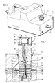
- the high-pressure cleaning device shown in the drawing comprises a housing 1, in which there is a high-pressure pump, not shown. This is carried out via a suction line 2 of cleaning liquid which is pumped into a pressure line 3 by the pump under high pressure.
- the pressure line ends in a spray lance or spray gun, not shown in the drawing, via which a jet of the desired shape can be emitted under high pressure.
- the pressure and the amount of the liquid discharged via the pressure line 3 can be set on a setting button 4 protruding from the housing 1, which, for example, actuates a metering valve in the pressure line or a meterable closing valve in a bypass line leading back to the suction line of the pump.
- a setting button 4 protruding from the housing 1, which, for example, actuates a metering valve in the pressure line or a meterable closing valve in a bypass line leading back to the suction line of the pump.
- a manometer 5 is arranged in the adjusting knob 4, which is designed as a rotary handle, and can be viewed from the top and indicates the pressure that prevails in the pressure line 3 itself or in a space connected to the pressure line. In this way, when setting the desired pressure and quantity values on the setting button 4, the operator can read these pressure values directly on the manometer and check and correct its adjustment. There is no additional space requirement for the manometer 5, since the setting button 4 is provided in any case.
- FIG. 2 A special embodiment of a pressure quantity regulation results from the illustration in FIG. 2.
- a housing 6 there is a cylindrical blind hole 7, through which the pressure line 8 passes.
- a bypass line 9 connects to the blind hole 7, which leads to the suction side of the high-pressure pump in a manner not shown in the drawing.
- an insert 10 is inserted in a sealed manner and has a central bore 11, the lower edge of which forms a valve seat 12.
- a valve body 13 bears against this valve seat and is screwed into a piston 14 which is displaceable in the blind hole 7.
- This piston 14 is sealed against the inner wall of the blind hole 7 by an annular seal 15, the valve body 13 pressed against the valve seat 12 by a helical spring 16 supported on the one hand on the insert 10 and on the other hand on the piston 14.
- the blind hole 7 is closed on its side opposite the bypass line 9 by a screwed screw plug 17, into which a shaft 19 connected to a grip part 18 is screwed, which projects downward from the screw plug 17 and whose end face 20 is a stop surface for the piston 14 forms.
- the shaft 19 is sealed off from the screw plug 17 by an annular seal 21; it can be screwed into the blind hole 7 to a greater or lesser extent by actuating the handle part 18.
- an injector 22 with a constriction is inserted into the pressure line 8, in the area of which a connecting line 23 branches off, which ends in the chamber 24, which the piston 14 on the one hand and the screw plug 17 and the shaft 19 on the other hand in the blind hole 7 form.
- the shaft 19 has a longitudinal channel 25 leading from its front end into the grip part 18, which leads to the manometer 5 in the adjusting knob 4 and thus connects it to the chamber 24.
- the manometer 5 indicates the pressure prevailing in the chamber 24.
- the manometer 5 is arranged in the handle part 18 so that it can be seen through a window 26 on the top of the adjusting knob.
- the pressure gauge 5 can be inserted into a blind hole 27 in an enlarged head part 28 formed in one piece with the shaft 19.
- a hood 29 provided with the transparent window 26 is pulled over this head part 28 is formed on its outer wall 30 as a grip surface, for example by a plurality of axially parallel ribs or the like.
- the bypass line 9 can be closed by hand by screwing the valve body 31 onto the valve seat 32. In this case, all of the liquid delivered by the high-pressure pump flows through the pressure line 8. If the valve body 31 is lifted from the valve seat 32 by turning the adjusting knob 4, the flow is divided, that is to say a part of the liquid reaches the suction side via the bypass line 9 the pump, while only a remainder is released via the pressure line. This also lowers the pressure in the blind hole 7, which is indicated by the manometer 5 in the adjusting knob 4 via the connection of the transverse bore 33 and the longitudinal channel 25. In this way too, the user finds out the respective position of the valve body 31 relative to the valve seat 32 via the pressure display and can thus set the desired pressure value and thus a desired delivery quantity.
- FIG. 4 differs from the embodiment of FIG. 3 essentially in that the head part 28 of the adjusting knob 4 is not formed in one piece with the shaft 19, but rather forms a separate component that is screwed onto the shaft 19 and glued to it, for example can be.
- the manometer itself can have a customary structure, it can transfer the displacement of a piston acting as a sensor to a pointer by means of mechanical deflecting elements, and the indicator can be displayed by a rotatably mounted pointer. In other cases it would also be a linear display possible by a correspondingly moving display element.
- pressure gauges of a known type could be used.
Landscapes
- Measuring Fluid Pressure (AREA)
Applications Claiming Priority (2)
| Application Number | Priority Date | Filing Date | Title |
|---|---|---|---|
| DE3932386A DE3932386C1 (enExample) | 1989-09-28 | 1989-09-28 | |
| DE3932386 | 1989-09-28 |
Publications (2)
| Publication Number | Publication Date |
|---|---|
| EP0494253A1 EP0494253A1 (de) | 1992-07-15 |
| EP0494253B1 true EP0494253B1 (de) | 1993-08-11 |
Family
ID=6390383
Family Applications (1)
| Application Number | Title | Priority Date | Filing Date |
|---|---|---|---|
| EP90915434A Expired - Lifetime EP0494253B1 (de) | 1989-09-28 | 1990-09-19 | Hochdruckreinigungsgerät |
Country Status (4)
| Country | Link |
|---|---|
| EP (1) | EP0494253B1 (enExample) |
| DE (2) | DE3932386C1 (enExample) |
| DK (1) | DK0494253T3 (enExample) |
| WO (1) | WO1991004804A1 (enExample) |
Families Citing this family (3)
| Publication number | Priority date | Publication date | Assignee | Title |
|---|---|---|---|---|
| DE19913230C2 (de) * | 1999-03-23 | 2001-06-21 | Vti Ventil Technik Gmbh | Ventilarmatur für einen Druckbehälter |
| DE202005001256U1 (de) * | 2005-01-26 | 2005-06-09 | Bürkert Werke GmbH & Co. KG | Ventil für ein fluides Medium |
| EP3812053B1 (de) | 2019-10-24 | 2025-06-11 | Andreas Stihl AG & Co. KG | Hochdruckreiniger und verfahren zur montage eines hochdruckreinigers |
Family Cites Families (5)
| Publication number | Priority date | Publication date | Assignee | Title |
|---|---|---|---|---|
| FR1142070A (fr) * | 1956-01-31 | 1957-09-13 | P Berthoud Ets | Perfectionnements aux dispositifs de manomètres pour pulvérisateurs agricoles et analogues |
| FR1381729A (fr) * | 1964-01-17 | 1964-12-14 | Robinetterie Chantoiseau | Valve pour la mesure des fluides |
| DE2725575A1 (de) * | 1977-06-07 | 1978-12-21 | Karl Hehl | Vorrichtung zum abwechselnden anschliessen eines manometers an verschiedene druckmesstellen |
| DE3248622C2 (de) * | 1982-12-30 | 1985-10-17 | Alfred Kärcher GmbH & Co, 7057 Winnenden | Hochdruckreinigungsgerät |
| DE8815807U1 (de) * | 1988-12-21 | 1989-11-02 | WAP Reinigungssysteme GmbH & Co, 7919 Bellenberg | Hochdruckreinigungsgerät mit Halterungsvorrichtung |
-
1989
- 1989-09-28 DE DE3932386A patent/DE3932386C1/de not_active Expired - Fee Related
-
1990
- 1990-04-13 DE DE9004298U patent/DE9004298U1/de not_active Expired - Lifetime
- 1990-09-19 DK DK90915434.6T patent/DK0494253T3/da active
- 1990-09-19 WO PCT/EP1990/001586 patent/WO1991004804A1/de not_active Ceased
- 1990-09-19 EP EP90915434A patent/EP0494253B1/de not_active Expired - Lifetime
Also Published As
| Publication number | Publication date |
|---|---|
| DK0494253T3 (da) | 1993-10-18 |
| DE3932386C1 (enExample) | 1990-12-20 |
| DE9004298U1 (de) | 1990-08-09 |
| EP0494253A1 (de) | 1992-07-15 |
| WO1991004804A1 (de) | 1991-04-18 |
Similar Documents
| Publication | Publication Date | Title |
|---|---|---|
| EP0315656B1 (de) | Infusionsgerät | |
| DE69712625T2 (de) | Austragsvorrichtung | |
| DE2206402C3 (de) | Spritzvorrichtung zum Ausspritzen einer mit Zusatzflüssigkeit vermischten Trägerflüssigkeit | |
| DE2343687B2 (de) | Dosiergeraet zur abgabe von fluessigkeit aus einem behaelter | |
| EP4079419A1 (de) | Hochdruckreinigungsgerät | |
| EP3991861A1 (de) | Hochdruckreinigungsgerät | |
| EP0183130A2 (de) | Zerstäuberdüse eines Flüssigkeitszerstäubers | |
| EP0494253B1 (de) | Hochdruckreinigungsgerät | |
| DE602004005962T2 (de) | Stiftartiger flüssigkeitsspender | |
| DE3736095C2 (enExample) | ||
| EP0927580B1 (de) | Handbrause | |
| DE3332189C1 (de) | Landwirtschaftliches Gerät zum dosierten Ausbringen von Flüssigkeiten | |
| WO2001053001A1 (de) | Strahlrohr für ein hochdruckreinigungsgerät | |
| DE2139870C3 (de) | Siphonflaschenverschluß | |
| DE2045997B2 (de) | Fluessigkeitskolbenpumpe zur uebertragung hydraulischer druckimpulse oder eines pulsierenden fluessigkeitsstrahles auf ein handgeraet zur koerperpflege | |
| DE4025114A1 (de) | Membran-dosierpumpe | |
| DE7428678U (de) | Druckschaltventil | |
| DE3003390A1 (de) | Druckluftschrauber mit einer einrichtung zum zufuehren und halten der schraube durch saugluft | |
| DE3018479A1 (de) | Ventil mit handbetaetigung | |
| DE3439235C2 (enExample) | ||
| DE2603776C2 (de) | Druckspüler mit zugeordneter Vorabsperrung | |
| DE1550184A1 (de) | Auslaufhahn | |
| CH667211A5 (en) | Oxygen supply and breathing appts. - has mask connected by flexible hose to valve block which is attached to bottle | |
| DE2242030B2 (de) | Hochdruckdosierpistole insbesondere zum Aufbringen einer Polierpaste | |
| DE4033009A1 (de) | Druckspueler |
Legal Events
| Date | Code | Title | Description |
|---|---|---|---|
| PUAI | Public reference made under article 153(3) epc to a published international application that has entered the european phase |
Free format text: ORIGINAL CODE: 0009012 |
|
| 17P | Request for examination filed |
Effective date: 19920205 |
|
| AK | Designated contracting states |
Kind code of ref document: A1 Designated state(s): DK GB IT |
|
| 17Q | First examination report despatched |
Effective date: 19921109 |
|
| GRAA | (expected) grant |
Free format text: ORIGINAL CODE: 0009210 |
|
| AK | Designated contracting states |
Kind code of ref document: B1 Designated state(s): DK GB IT |
|
| GBT | Gb: translation of ep patent filed (gb section 77(6)(a)/1977) |
Effective date: 19930820 |
|
| ITF | It: translation for a ep patent filed | ||
| REG | Reference to a national code |
Ref country code: DK Ref legal event code: T3 |
|
| PLBE | No opposition filed within time limit |
Free format text: ORIGINAL CODE: 0009261 |
|
| STAA | Information on the status of an ep patent application or granted ep patent |
Free format text: STATUS: NO OPPOSITION FILED WITHIN TIME LIMIT |
|
| 26N | No opposition filed | ||
| PGFP | Annual fee paid to national office [announced via postgrant information from national office to epo] |
Ref country code: GB Payment date: 19980914 Year of fee payment: 9 |
|
| PG25 | Lapsed in a contracting state [announced via postgrant information from national office to epo] |
Ref country code: GB Free format text: LAPSE BECAUSE OF NON-PAYMENT OF DUE FEES Effective date: 19990919 |
|
| GBPC | Gb: european patent ceased through non-payment of renewal fee |
Effective date: 19990919 |
|
| PGFP | Annual fee paid to national office [announced via postgrant information from national office to epo] |
Ref country code: DK Payment date: 20020919 Year of fee payment: 13 |
|
| PG25 | Lapsed in a contracting state [announced via postgrant information from national office to epo] |
Ref country code: DK Free format text: LAPSE BECAUSE OF NON-PAYMENT OF DUE FEES Effective date: 20030930 |
|
| REG | Reference to a national code |
Ref country code: DK Ref legal event code: EBP |
|
| PG25 | Lapsed in a contracting state [announced via postgrant information from national office to epo] |
Ref country code: IT Free format text: LAPSE BECAUSE OF NON-PAYMENT OF DUE FEES Effective date: 20050919 |