EP0490279A2 - Leuchtkasten - Google Patents
Leuchtkasten Download PDFInfo
- Publication number
- EP0490279A2 EP0490279A2 EP91120925A EP91120925A EP0490279A2 EP 0490279 A2 EP0490279 A2 EP 0490279A2 EP 91120925 A EP91120925 A EP 91120925A EP 91120925 A EP91120925 A EP 91120925A EP 0490279 A2 EP0490279 A2 EP 0490279A2
- Authority
- EP
- European Patent Office
- Prior art keywords
- light
- reflector
- optical film
- light source
- box according
- Prior art date
- Legal status (The legal status is an assumption and is not a legal conclusion. Google has not performed a legal analysis and makes no representation as to the accuracy of the status listed.)
- Withdrawn
Links
Images
Classifications
-
- F—MECHANICAL ENGINEERING; LIGHTING; HEATING; WEAPONS; BLASTING
- F21—LIGHTING
- F21V—FUNCTIONAL FEATURES OR DETAILS OF LIGHTING DEVICES OR SYSTEMS THEREOF; STRUCTURAL COMBINATIONS OF LIGHTING DEVICES WITH OTHER ARTICLES, NOT OTHERWISE PROVIDED FOR
- F21V7/00—Reflectors for light sources
-
- G—PHYSICS
- G02—OPTICS
- G02F—OPTICAL DEVICES OR ARRANGEMENTS FOR THE CONTROL OF LIGHT BY MODIFICATION OF THE OPTICAL PROPERTIES OF THE MEDIA OF THE ELEMENTS INVOLVED THEREIN; NON-LINEAR OPTICS; FREQUENCY-CHANGING OF LIGHT; OPTICAL LOGIC ELEMENTS; OPTICAL ANALOGUE/DIGITAL CONVERTERS
- G02F1/00—Devices or arrangements for the control of the intensity, colour, phase, polarisation or direction of light arriving from an independent light source, e.g. switching, gating or modulating; Non-linear optics
- G02F1/01—Devices or arrangements for the control of the intensity, colour, phase, polarisation or direction of light arriving from an independent light source, e.g. switching, gating or modulating; Non-linear optics for the control of the intensity, phase, polarisation or colour
- G02F1/13—Devices or arrangements for the control of the intensity, colour, phase, polarisation or direction of light arriving from an independent light source, e.g. switching, gating or modulating; Non-linear optics for the control of the intensity, phase, polarisation or colour based on liquid crystals, e.g. single liquid crystal display cells
- G02F1/133—Constructional arrangements; Operation of liquid crystal cells; Circuit arrangements
- G02F1/1333—Constructional arrangements; Manufacturing methods
- G02F1/1335—Structural association of cells with optical devices, e.g. polarisers or reflectors
- G02F1/1336—Illuminating devices
- G02F1/133602—Direct backlight
- G02F1/133605—Direct backlight including specially adapted reflectors
-
- G—PHYSICS
- G09—EDUCATION; CRYPTOGRAPHY; DISPLAY; ADVERTISING; SEALS
- G09F—DISPLAYING; ADVERTISING; SIGNS; LABELS OR NAME-PLATES; SEALS
- G09F13/00—Illuminated signs; Luminous advertising
- G09F13/04—Signs, boards or panels, illuminated from behind the insignia
- G09F13/0409—Arrangements for homogeneous illumination of the display surface, e.g. using a layer having a non-uniform transparency
-
- G—PHYSICS
- G09—EDUCATION; CRYPTOGRAPHY; DISPLAY; ADVERTISING; SEALS
- G09F—DISPLAYING; ADVERTISING; SIGNS; LABELS OR NAME-PLATES; SEALS
- G09F13/00—Illuminated signs; Luminous advertising
- G09F13/04—Signs, boards or panels, illuminated from behind the insignia
- G09F13/0418—Constructional details
- G09F13/0422—Reflectors
-
- G—PHYSICS
- G09—EDUCATION; CRYPTOGRAPHY; DISPLAY; ADVERTISING; SEALS
- G09F—DISPLAYING; ADVERTISING; SIGNS; LABELS OR NAME-PLATES; SEALS
- G09F13/00—Illuminated signs; Luminous advertising
- G09F13/04—Signs, boards or panels, illuminated from behind the insignia
- G09F13/14—Arrangements of reflectors therein
-
- G—PHYSICS
- G02—OPTICS
- G02F—OPTICAL DEVICES OR ARRANGEMENTS FOR THE CONTROL OF LIGHT BY MODIFICATION OF THE OPTICAL PROPERTIES OF THE MEDIA OF THE ELEMENTS INVOLVED THEREIN; NON-LINEAR OPTICS; FREQUENCY-CHANGING OF LIGHT; OPTICAL LOGIC ELEMENTS; OPTICAL ANALOGUE/DIGITAL CONVERTERS
- G02F1/00—Devices or arrangements for the control of the intensity, colour, phase, polarisation or direction of light arriving from an independent light source, e.g. switching, gating or modulating; Non-linear optics
- G02F1/01—Devices or arrangements for the control of the intensity, colour, phase, polarisation or direction of light arriving from an independent light source, e.g. switching, gating or modulating; Non-linear optics for the control of the intensity, phase, polarisation or colour
- G02F1/13—Devices or arrangements for the control of the intensity, colour, phase, polarisation or direction of light arriving from an independent light source, e.g. switching, gating or modulating; Non-linear optics for the control of the intensity, phase, polarisation or colour based on liquid crystals, e.g. single liquid crystal display cells
- G02F1/133—Constructional arrangements; Operation of liquid crystal cells; Circuit arrangements
- G02F1/1333—Constructional arrangements; Manufacturing methods
- G02F1/1335—Structural association of cells with optical devices, e.g. polarisers or reflectors
- G02F1/1336—Illuminating devices
- G02F1/133602—Direct backlight
- G02F1/133604—Direct backlight with lamps
-
- G—PHYSICS
- G09—EDUCATION; CRYPTOGRAPHY; DISPLAY; ADVERTISING; SEALS
- G09F—DISPLAYING; ADVERTISING; SIGNS; LABELS OR NAME-PLATES; SEALS
- G09F13/00—Illuminated signs; Luminous advertising
- G09F13/04—Signs, boards or panels, illuminated from behind the insignia
- G09F13/14—Arrangements of reflectors therein
- G09F2013/145—Arrangements of reflectors therein curved reflectors
Definitions
- the invention is directed to a light box having a case with a back-lit front side, a light source for backlighting said front side, and a reflector with a curved reflector surface having provided thereon an optical film of material impervious to light, said film, on the surface thereof directed towards the light source, being provided with substantially V-shaped grooves arranged side by side and in parallel to each other.
- the main problem with light boxes consists in that the front side or wall, carrying a signing, i.e. information, has to be illuminated evenly although a plurality of point sources of light or elongated sources of light (luminescent or fluorescent tubes) are used.
- Light boxes are installed wherever an information-carrying surface is to be back-lit by light. Therefore, light boxes are used primarily for back-lit posters, pictures, sign plates and the like. However, light boxes find also application as working place luminaires because they emit the light relatively evenly onto the working place. Further, light boxes are used for the backlighting of liquid crystal displays.
- a light box of the initially mentioned type is known from US-PS 4,874,228.
- This known light box comprises a box substantially rectangular in section, with a (elongated) light source being arranged in one peripheral area of said box.
- a reflector having a reflector surface with a transparent optical film arranged thereon.
- Said optical film has an even surface showing towards the reflector surface and a structured surface provided with a plurality of substantially V-shaped grooves arranged side by side and in parallel to each other, i.e. a plurality of prisms arranged without mutual distances.
- Transparent optical films of this kind are also used for light transmission in air.
- the prisms or grooves run parallel to the extension of the light source, i.e. parallel to the tube.
- the beams incident on the structured surface of the optical film traveling at relatively small angles of less than 20 degrees with respect to the even surface of the optical film, are either (totally) reflected or, while being refracted, penetrate into the optical film and are reflected on the reflector surface and then, after again penetrating the optical film, exit in the direction of the front side to be back-lit.
- the reflector, and thus also the optical film does not extend in the immediate vicinity of the light source, i.e. is not arranged in the region near the light source.
- the light source is arranged in the central area of the reflector and that the V-shaped grooves are oriented transverse to the extension of the light source.
- the reflector is arranged along both longitudinal sides of the elongated light source; thus, the reflector surface projects beyond the light source transverse to the longitudinal extension thereof. Accordingly, the light source is located in the central area of the reflector.
- the orientation or structure, resp. of the optical film on the reflector surface is such that the grooves or prisms run vertical to the longitudinal extension of the light source.
- the reflector (optical film) is curved and preferably has a varying radius of curvature.
- the optical film By the structure of the optical film being oriented transverse to the extension of the light source, it is accomplished that those light beams which impinge on the reflector immediately near the light source are reflected past the side of the light source onto the front side and, therefore, do not add to the light aimed directly from the light source to the front side. As a result, there is provided a more uniform illumination of the front side in the central area thereof where the light from the light source impinges directly thereonto. This is particularly advantageous in flat light boxes since, due to the closeness of the front side to the light source, the front side tends to be illuminated more intensely in the area of the light source. This effect is evidently reduced in the light box of the invention.
- the optical film is flexible but is provided with some stability of shape, i.e. a certain bending resistance. Thus, the optical film substantially maintains its form and position when not being subjected to external forces.
- the flanks of the V-shaped grooves extend with respect to each other.
- Particularly favorable optical characteristics are obtained if the flanks of the optical film are oriented at a mutual angle of 90 degrees, with each flank arranged at an angle of 45 degrees relative to the even underside of the film.
- the total thickness of the optical film is about 0.5 mm, the depth of the V-shaped grooves being about 0.17 mm and the width of the opening thereof being about 0.35 mm, resp.
- the material of the optical film consists of polycarbonate or polymethylmethacrylate.
- an elongated lamp particularly a fluorescent tube
- a string of point sources of light is suitable.
- an elongated light source is any light source with strip-shaped light radiation.
- Fluorescent tubes offer the advantage that light is emitted not just radially, as in a luminous filament, but (with the tube being seen from the side) from a relatively wide area of the strip, namely the area of the longitudinal section of the tube. Thereby, the angles of incidence of the light beams are equal or substantially equal over wide areas of the reflector, resulting in equal or similar reflections.
- a light source emitting light out of different distances to the reflector illuminates the reflector in a more uniform manner than a light source comprising a luminous filament.
- a more uniform illumination of the reflector contributes to a more uniform illumination of the front side.
- the reflector surface under the optical film is provided for diffuse reflection; particularly, this surface is a mat white surface.
- the portion of light entering into the optical film (depending on the angle of incidence of the light beams) is reflected diffusely, i.e. with a certain scattering or spreading.
- the peripheral areas of the reflector extending in parallel to the longitudinal dimension of the light source, are not covered by the optical film but are exposed. These peripheral areas reflect the light diffusely and thus add to the spreading of the light in the peripheral area of the front side.
- the light source is arranged in the immediate vicinity of the structured surface of the optical film, e.g. in a distance of about 5 mm.
- the curvature of the reflector surface in the area near the light source, i.e. in the central area, is stronger than in the remaining area of reflector surface.
- the reflector surface is curved in a parabola.
- the uniform light distribution on the front side of the light box is effected primarily by reflection and refraction of the light on the optical film having the above-described surface structure.
- a light-scattering diffusion plate as it is usually found in light boxes, is not needed at the front side. While in those light boxes which strictly require a diffusion plate for obtaining relatively uniform light distribution at the back-lit surface, comparatively large losses occur in the diffusion plate, this is not the case in the light box of the invention because here the uniform light distribution is not, or at least not primarily so, effected by a diffusion plate. Accordingly, light sources having low light intensity and thus being less energy-consuming can be used for the light box of the invention. For accomplishing a still more uniform light distribution on the front side, a diffusion plate can be provided also in the light box of the invention.
- a liquid-crystal display at the front side of the light box is possible.
- These display means for obtaining high-contrast representation over the whole display area, necessitate uniform backlighting which, as explained above, is provided by the light box of the invention.
- the front side is provided with a optical film having the same structure as the optical film of the reflector.
- the surface structure is arranged on the inner surface of the optical film while the V-shaped grooves can extend both parallel or at right angles to the light source.
- Such an arrangement of the optical film effects a desired light-orientation.
- the optical film at the front side of the light box has the advantage that the person working at said working place is not dazzled by the light beams illuminating the working place.
- the arrangement can be such that the surface structure is arranged on the outer surface of the optical film. In this case, too, the V-shaped grooves can be oriented transverse or parallel to the longitudinal extension of the light source. If the surface structure is provided on the outer surface, the light is subjected to a focussing effect.
- a mounting means having at least one resilient holding element to be plugged onto the light source, the optical film of the reflector having its central portion fastened to said resilient holding element.
- the optical film and the light source fluorescent tube
- the holding elements are interconnected and kept at a distance from each other.
- two or three holding elements are required. Due to the resilience of the holding elements, caused by the construction as well as by the material of the holding elements, the holding elements can be easily plugged onto the fluorescent tube and removed therefrom.
- the holding elements are preferably made from a transparent material, the optical film being bonded to the holding element by a transparent plastic adhesive. By withdrawing the holding elements from the fluorescent tube, the optical film of the reflector can be easily removed, e.g. for being replaced by a new one.
- the above-described mounting device for holding the optical film at the fluorescent tube is advantageous particularly with respect to the mounting and maintenance of the light box.
- the optical film of the reflector is held attached to the fluorescent tube by said holding elements only in the central area of the optical film, the remaining area thereof being supported on the reflector surface.
- the optical film is firmly secured on the reflector surface.
- the construction of the holding elements is such that, with the holding element remaining immovable, the fluorescent tube can be rotated about the longitudinal axis thereof.
- the holding element is provided with a resilient clamping member surrounding the fluorescent tube over an angle of more than 180 degrees, preferably up to 270 degrees.
- This clampingly mountable holding member has formed thereon a radial spacing bar.
- a supporting bar is attached to the free end of said spacing bar, the optical film being fastened thereto (by bonding).
- the supporting bar is preferably adapted to the curvature of the reflector in the area close to the light source, i.e. in the central portion.
- the optical film by being fastened to the supporting bar, is given a curvature corresponding to that of the reflector.
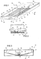
- Fig. 1 is a perspective view of a light box 10, with the side walls and the back-lit front wall being partially broken away to reveal the interior construction of light box 10.
- the light box 10 has a parallelepiped case 12 consisting of a rear wall 14, four side walls 16,18 arranged at right angles to each other, and a front wall 20 opposite to rear wall 14. While the rear wall and the side walls of case 12 are made from sheet metal, the front wall 20 consists of a light-impervious plastics material and acts as a light-scattering diffusion plate.
- the transparent front wall 20 is the back-lit front side 21 of the light box 10.
- a reflector 22 is arranged which, as seen in sectional view through light box 10, is arranged as a concavely curved plate having its lowermost portion abutting the rear wall 14.
- the concave reflector surface 24, being directed to front side 20, has its surface painted mat white.
- a light source consisting of a fluorescent tube 26 extending in parallel to the longitudinal side walls 16 of case 12 and at a constant distance from side walls 16. (The longitudinal side walls 16 are the longer walls among the four side walls of case 12.)
- the reflector surface 24 has its central portion provided with a film 28 which, as evident from Fig. 2, has an even lower surface resting on reflector surface 24 and a structured upper surface facing the fluorescent lamp 26.
- Said film 28 is a so-called optical film of transparent material, e.g. polycarbonate or polymethylmethacrylate.
- the surface of the optical film 28 directed towards lamp 26 is provided with a plurality of V-shaped grooves 30 extending over the width of the optical film 28 and being arranged parallel and in direct abutment to each other. Because of the V-shaped section, prisms 32 are formed between neighboring grooves 30. The flanks of the V-shaped grooves 30 or, resp.
- the flanks of the prisms 32 are perpendicular to each other, extending at an angle of 45 degrees to the even surface of the optical film 28.
- the V-shaped grooves 30 or, resp. the prisms 32 extend perpendicular to the longitudinal axis of the fluorescent tube 26, i.e. transversely to the longitudinal dimension of the elongated light source of light box 10.
- peripheral portions 34 are generated on the reflector 22. Said peripheral portions 34 are in abutment to the two longitudinal side walls 16 of case 12 and are exposed, i.e. are not provided with the optical film 28.
- the two peripheral portions 34 are parallel to the fluorescent tube 26 and are mat white.
- the optical film 28 is mounted at the fluorescent tube 26 by a mounting means.
- the mounting means consists of three holding elements 36 distributed over the length of the fluorescent tube 26 and fabricated from a resilient transparent material.
- the holding elements 36 are provided with a clamping member of C-shaped section, enclosing the fluorescent tube 26 over a sector of more than 180 degrees, preferably up to 270 degrees.
- the clamping member is a cylindrical sleeve 38 which, in one circumfertial portion thereof, has a gap 39 extending axially over the length of said sleeve. Through this gap 39, sleeve 38 is shifted onto the fluorescent tube 26. With the sleeve 38 being mounted on the fluorescent tube 26, the sleeve 38 is spread, thus exerting a clamping force on fluorescent tube 26. In this manner, the holding element 36 is secured on the fluorescent tube 26.
- the sleeve 38 has a spacing bar 40 formed thereon, being arranged diametrically opposite to gap 39 and extending radially to sleeve 38.
- the radial orientation of said spacing bar 40 determines the distance between the optical film 28 and the fluorescent tube 26.
- the free end of spacing bar 40 being averted from sleeve 38, is joined by a supporting bar 42 which extends transverse to spacing bar 40 and, in the range of the fluorescent tube 26, is adapted to the curvature of reflector 22 and has the optical film 28 attached thereto by a transparent adhesive 44 (cf. Fig. 2).
- the optical film 28 lies on the reflector surface 24 of the reflector and is maintained in its position exclusively by the holding elements 36 plugged onto the fluorescent tube 26.
- the fluorescent tube 26, in turn, is mounted within case 12 by the sockets at the ends of tube 26 (the sockets being omitted in the Figures for reasons of clarity).
- the thickness of the optical film and the surface structure thereof are not represented in their real dimensions with respect to the other parts of the light box since, if the Figures were true to scale, the optical film would not be visible anymore.
- the light box has a width of about 40 cm, a length of 70 cm and a height of about 7 cm
- the optical film has a thickness of about 0.5 mm
- the height of the prisms 32 (or the depth of the grooves 30) being about 0.17 mm
- the distance of adjacent prisms being about 0.35 mm.
- the fluorescent tube 26 is arranged at a distance of about 5 mm to the optical film 28; for the better understanding of the invention, also this aspect is not shown in correct scale in the Figures.
- the front side 21 of light box 10 has placed thereon, e.g. a back-lit poster or a photograph arranged on the transparent front wall 20 of case 12.
- the front wall 20 is back-lit by the light of the fluorescent tube 26. Illumination of the front wall 20 is effected, on the one hand, by light beams emitted from the upper portion of fluorescent tube 26 and incident directly onto the inner side of front wall 20. On the other hand, however, illumination of the front wall 20 is also effected by light emitted from the lower portion, i.e. the lower half of fluorescent tube 26, and being reflected by the optical film 28 or by the exposed strips of the peripheral portions 34 of the reflector towards the front wall 20.
- the light beams impinging on optical film 28 are either reflected by the flanks of the V-shaped grooves 30 and prisms 32 or, being refracted, penetrate into the optical film 28 and are diffusely reflected by the underlying reflector surface 24 of reflector 22 and, after penetrating the optical film 28 repeatedly or undergoing multiple reflection within the optical film, exit in the direction of front wall 20.
- reflection is diffuse because the entire reflector surface 24 is mat white. Due to said diffuse reflection in the peripheral portions 34 of reflector 22, a scattering of the impinging light occurs in these areas, resulting in a more uniform light distribution in the area of the longitudinal edges of front wall 20.
- the light beams are for the largest part reflected past the fluorescent tube 26 towards the front wall 20.
- those light beams which are reflected in the immediate vicinity of fluorescent tube 26 do not penetrate the fluorescent tube 26 and, therefore, do not add to the portion of light emitted directly from the fluorescent tube 26 towards the front wall.
- those light beams which are reflected due to the structured shape of the surface of optical film 28 in the area of the fluorescent tube 26 contribute to an additional illumination of areas immediately near the fluorescent tube 26. As a result, illumination of the central area of front wall 20 is more uniform.
- the light beams exit at different distances to the reflector 22 or, resp. to the optical film 28.
- the light beams impinge at subtantially equal angles of incidence in wide areas of reflector 22 or, resp. optical film 28 so that subtantially equal reflections are obtained.
- this effect adds to a still more uniform illumination of the front wall 20.
- the optical film 28 having V-shaped grooves 30 and prisms 32 extending transverse to the longitudinal dimension of fluorescent tube 26 extending transverse to the longitudinal dimension of fluorescent tube 26, uniform light distribution is accomplished within the box 10 between the reflector 22 and the front wall 20 to be back-lit. Therefore, the uniform illumination of the front side of the light box need not be "paid for" by a diffusion plate to be arranged in that location.
- the light box as described here and shown in the Figures can be evenly illuminated by a 25 Watt fluorescent tube without identifiable variations in luminance on the front side 21 of light box 10.
Landscapes
- Physics & Mathematics (AREA)
- General Physics & Mathematics (AREA)
- Engineering & Computer Science (AREA)
- Theoretical Computer Science (AREA)
- Nonlinear Science (AREA)
- Crystallography & Structural Chemistry (AREA)
- Optics & Photonics (AREA)
- Chemical & Material Sciences (AREA)
- General Engineering & Computer Science (AREA)
- Mathematical Physics (AREA)
- Illuminated Signs And Luminous Advertising (AREA)
- Devices For Indicating Variable Information By Combining Individual Elements (AREA)
- Optical Elements Other Than Lenses (AREA)
- Liquid Crystal (AREA)
Applications Claiming Priority (2)
| Application Number | Priority Date | Filing Date | Title |
|---|---|---|---|
| DE4039291A DE4039291A1 (de) | 1990-12-08 | 1990-12-08 | Leuchtbox |
| DE4039291 | 1990-12-08 |
Publications (2)
| Publication Number | Publication Date |
|---|---|
| EP0490279A2 true EP0490279A2 (de) | 1992-06-17 |
| EP0490279A3 EP0490279A3 (en) | 1992-11-25 |
Family
ID=6419935
Family Applications (1)
| Application Number | Title | Priority Date | Filing Date |
|---|---|---|---|
| EP19910120925 Withdrawn EP0490279A3 (en) | 1990-12-08 | 1991-12-06 | Light box |
Country Status (5)
| Country | Link |
|---|---|
| US (1) | US5224770A (de) |
| EP (1) | EP0490279A3 (de) |
| JP (2) | JPH0496912U (de) |
| CA (1) | CA2057154A1 (de) |
| DE (1) | DE4039291A1 (de) |
Cited By (10)
| Publication number | Priority date | Publication date | Assignee | Title |
|---|---|---|---|---|
| WO1995002785A1 (en) * | 1993-07-15 | 1995-01-26 | Honeywell Inc. | Backlight apparatus with increased reflectance |
| WO1997001726A1 (en) * | 1995-06-26 | 1997-01-16 | Minnesota Mining And Manufacturing Company | Backlight system with multilayer optical film reflector |
| GB2310525A (en) * | 1996-02-24 | 1997-08-27 | Ronnie Revell | Illuminated display device |
| WO1998058361A1 (en) * | 1997-06-19 | 1998-12-23 | Hidekatsu Takahashi | Apparatus for neon light display |
| EP1113296A3 (de) * | 1999-11-29 | 2003-03-12 | Ando Electric Co., Ltd. | V-Rille Gitterspiegel und Lichtquelle mit variablen Wellenlänge und externem Resonator |
| US6893135B2 (en) | 2000-03-16 | 2005-05-17 | 3M Innovative Properties Company | Light guides suitable for illuminated displays |
| EP1586813A1 (de) | 2004-04-16 | 2005-10-19 | 3M Innovative Properties Company | Leuchtkasten |
| WO2006028719A2 (en) | 2004-09-01 | 2006-03-16 | 3M Innovative Properties Company | Light box |
| CN102606914A (zh) * | 2008-11-28 | 2012-07-25 | 富士迈半导体精密工业(上海)有限公司 | 室内灯具 |
| DE102012012649A1 (de) * | 2012-06-26 | 2014-01-16 | Bartenbach Holding Gmbh | Beleuchtungsvorrichtung |
Families Citing this family (33)
| Publication number | Priority date | Publication date | Assignee | Title |
|---|---|---|---|---|
| JPH0792577A (ja) * | 1993-09-21 | 1995-04-07 | Mita Ind Co Ltd | 光学系用導電体 |
| DE4416360A1 (de) * | 1994-05-09 | 1995-11-16 | Egbert E Cohausz | Elektrisches Anzeigeelement |
| US5481637A (en) * | 1994-11-02 | 1996-01-02 | The University Of British Columbia | Hollow light guide for diffuse light |
| DE19520822C1 (de) * | 1995-05-30 | 1996-09-05 | Aeg Schienenfahrzeuge | Linien-, Ziel- oder Haltestellenanzeige |
| US6080467A (en) * | 1995-06-26 | 2000-06-27 | 3M Innovative Properties Company | High efficiency optical devices |
| DE29519708U1 (de) * | 1995-12-12 | 1997-04-10 | Zumtobel Licht Gmbh, Dornbirn | Leuchte mit wenigstens einem langgestreckten Leuchtmittel |
| ES2114802B1 (es) * | 1996-01-22 | 1999-02-16 | Juan Roura Y Cia S A | Perfeccionamientos en los dispositivos de iluminacion rotulos y similares. |
| US6582103B1 (en) | 1996-12-12 | 2003-06-24 | Teledyne Lighting And Display Products, Inc. | Lighting apparatus |
| US6031958A (en) * | 1997-05-21 | 2000-02-29 | Mcgaffigan; Thomas H. | Optical light pipes with laser light appearance |
| US5976686A (en) * | 1997-10-24 | 1999-11-02 | 3M Innovative Properties Company | Diffuse reflective articles |
| US6497946B1 (en) * | 1997-10-24 | 2002-12-24 | 3M Innovative Properties Company | Diffuse reflective articles |
| DE29903298U1 (de) | 1999-02-24 | 1999-05-12 | Trilux-Lenze Gmbh + Co Kg, 59759 Arnsberg | Leuchte |
| US20040005451A1 (en) * | 1999-08-03 | 2004-01-08 | Minnesota Mining And Manufacturing Company | Diffuse reflective articles |
| JP2002244127A (ja) * | 2001-01-31 | 2002-08-28 | Internatl Business Mach Corp <Ibm> | 液晶表示装置、サイドライト型バックライト・ユニット、ランプ・リフレクタおよび反射部材 |
| RU2185644C1 (ru) * | 2001-06-08 | 2002-07-20 | Социленков Александр Александрович | Световозвращатель |
| JP3939684B2 (ja) * | 2003-07-25 | 2007-07-04 | エルジー.フィリップス エルシーデー カンパニー,リミテッド | 液晶表示装置のバックライト装置及びこれに使用される反射手段 |
| JP4133663B2 (ja) * | 2003-07-30 | 2008-08-13 | 三菱電機株式会社 | 面状光源装置および該装置を備えた表示装置 |
| USD498016S1 (en) | 2003-11-26 | 2004-11-02 | Acuity Brands, Inc. | Portion of a combined lighting fixture and hanger |
| USD496745S1 (en) | 2003-11-26 | 2004-09-28 | Acuity Brands, Inc. | Portion of a combined lighting fixture and hanger |
| US20050222801A1 (en) * | 2004-04-06 | 2005-10-06 | Thomas Wulff | System and method for monitoring a mobile computing product/arrangement |
| GB0427607D0 (en) * | 2004-12-16 | 2005-01-19 | Microsharp Corp Ltd | Structured optical film |
| EP1866153A1 (de) * | 2005-03-24 | 2007-12-19 | 3M Innovative Properties Company | Korrosionsfeste, metallisierte folien und herstellungsverfahren dafür |
| US20080311349A1 (en) * | 2005-03-24 | 2008-12-18 | Johnson Michael A | Metallized Films and Articles Containing the Same |
| US20060291241A1 (en) * | 2005-06-22 | 2006-12-28 | Carmanah Technologies Corp. | Light emitting diode illuminated display panel assembly |
| US20060289054A1 (en) * | 2005-06-22 | 2006-12-28 | Carmanah Technologies Corp. | Solar powered light emitting diode illuminated display panel assembly |
| US7180779B2 (en) * | 2005-07-11 | 2007-02-20 | Atmel Corporation | Memory architecture with enhanced over-erase tolerant control gate scheme |
| US8594742B2 (en) * | 2006-06-21 | 2013-11-26 | Symbol Technologies, Inc. | System and method for monitoring a mobile device |
| JP2008041328A (ja) * | 2006-08-02 | 2008-02-21 | Nippon Zeon Co Ltd | 直下型バックライト装置 |
| US20100129779A1 (en) * | 2008-11-22 | 2010-05-27 | Pomerleau Kevin L | Image Capture and Tracing System and Method |
| US8568002B2 (en) * | 2010-03-05 | 2013-10-29 | Southpac Trust International Inc., Trustee of the LDH Trust | Light diffusion and condensing fixture |
| US9188290B2 (en) * | 2012-04-10 | 2015-11-17 | Cree, Inc. | Indirect linear fixture |
| CN107845349B (zh) * | 2017-12-21 | 2024-10-08 | 南宁一棵树标识制作有限公司 | 一种铝塑板镶嵌亚克力发光字体结构 |
| USD1009348S1 (en) * | 2019-12-20 | 2023-12-26 | Abl Ip Holding Llc | Light fixture |
Family Cites Families (22)
| Publication number | Priority date | Publication date | Assignee | Title |
|---|---|---|---|---|
| US2175067A (en) * | 1938-04-23 | 1939-10-03 | Holophane Co Inc | Prismatic reflector |
| US2290282A (en) * | 1939-10-27 | 1942-07-21 | Herr Max | Piano lamp |
| US2348617A (en) * | 1941-02-19 | 1944-05-09 | Sun Kraft Inc | Ultraviolet ray generator |
| US3944807A (en) * | 1975-01-20 | 1976-03-16 | White-Westinghouse Corporation | Infrared lamp holder |
| NO139653C (no) * | 1975-11-14 | 1979-04-18 | Colorlux As | Lysskiltkasse. |
| US4154219A (en) * | 1977-03-11 | 1979-05-15 | E-Systems, Inc. | Prismatic solar reflector apparatus and method of solar tracking |
| US4120565A (en) * | 1977-06-16 | 1978-10-17 | The United States Of America As Represented By The United States Department Of Energy | Prisms with total internal reflection as solar reflectors |
| US4233651A (en) * | 1978-03-30 | 1980-11-11 | Keene Corporation | Work area lighting system |
| US4260220A (en) * | 1979-06-15 | 1981-04-07 | Canadian Patents And Development Limited | Prism light guide having surfaces which are in octature |
| US4615579A (en) * | 1983-08-29 | 1986-10-07 | Canadian Patents & Development Ltd. | Prism light guide luminaire |
| CA1279783C (en) * | 1985-11-21 | 1991-02-05 | Minnesota Mining And Manufacturing Company | Totally internally reflecting thin, flexible film |
| US4805984A (en) * | 1985-11-21 | 1989-02-21 | Minnesota Mining And Manufacturing Company | Totally internally reflecting light conduit |
| US4850665A (en) * | 1987-02-20 | 1989-07-25 | Minnesota Mining And Manufacturing Company | Method and apparatus for controlled emission of light from prism light guide |
| DE3806421A1 (de) * | 1987-03-04 | 1988-11-24 | Citizen Watch Co Ltd | Beleuchtungsvorrichtung fuer ein fluessigkristallanzeigegeraet |
| US4874228A (en) * | 1987-03-24 | 1989-10-17 | Minnesota Mining And Manufacturing Company | Back-lit display |
| US4834495A (en) * | 1987-05-08 | 1989-05-30 | Minnesota Mining And Manufacturing Company | Collapsible light pipe |
| US4791540A (en) * | 1987-05-26 | 1988-12-13 | Minnesota Mining And Manufacturing Company | Light fixture providing normalized output |
| JPH024906A (ja) * | 1988-06-22 | 1990-01-09 | Takeshi Masumoto | フレーク状急冷凝固金属粉末の製造法 |
| US5054885A (en) * | 1988-10-11 | 1991-10-08 | Minnesota Mining And Manfuacturing Company | Light fixture including a partially collimated beam of light and reflective prisms having peaks lying on a curved surface |
| US5034864A (en) * | 1989-04-25 | 1991-07-23 | Mitsubishi Rayon Co., Ltd. | Planar light-source device and illumination apparatus using the same |
| US5006966A (en) * | 1989-08-30 | 1991-04-09 | Transmatic, Inc. | Transit vehicle lighting fixture |
| US5029060A (en) * | 1990-07-17 | 1991-07-02 | Minnesota Mining And Manufacturing Company | Uniform intensity profile catadioptric lens |
-
1990
- 1990-12-08 DE DE4039291A patent/DE4039291A1/de not_active Withdrawn
-
1991
- 1991-12-05 US US07/803,179 patent/US5224770A/en not_active Expired - Fee Related
- 1991-12-06 JP JP10082191U patent/JPH0496912U/ja active Pending
- 1991-12-06 CA CA002057154A patent/CA2057154A1/en not_active Abandoned
- 1991-12-06 EP EP19910120925 patent/EP0490279A3/en not_active Withdrawn
- 1991-12-09 JP JP1991101156U patent/JPH0496775U/ja active Pending
Cited By (12)
| Publication number | Priority date | Publication date | Assignee | Title |
|---|---|---|---|---|
| WO1995002785A1 (en) * | 1993-07-15 | 1995-01-26 | Honeywell Inc. | Backlight apparatus with increased reflectance |
| WO1997001726A1 (en) * | 1995-06-26 | 1997-01-16 | Minnesota Mining And Manufacturing Company | Backlight system with multilayer optical film reflector |
| GB2310525A (en) * | 1996-02-24 | 1997-08-27 | Ronnie Revell | Illuminated display device |
| WO1998058361A1 (en) * | 1997-06-19 | 1998-12-23 | Hidekatsu Takahashi | Apparatus for neon light display |
| EP1113296A3 (de) * | 1999-11-29 | 2003-03-12 | Ando Electric Co., Ltd. | V-Rille Gitterspiegel und Lichtquelle mit variablen Wellenlänge und externem Resonator |
| US6597507B1 (en) | 1999-11-29 | 2003-07-22 | Ando Electric Co., Ltd. | V-groove grating mirror and external resonator type wavelength variable light source using the mirror |
| US6893135B2 (en) | 2000-03-16 | 2005-05-17 | 3M Innovative Properties Company | Light guides suitable for illuminated displays |
| EP1586813A1 (de) | 2004-04-16 | 2005-10-19 | 3M Innovative Properties Company | Leuchtkasten |
| WO2005106321A1 (en) | 2004-04-16 | 2005-11-10 | 3M Innovative Properties Company | Light box |
| WO2006028719A2 (en) | 2004-09-01 | 2006-03-16 | 3M Innovative Properties Company | Light box |
| CN102606914A (zh) * | 2008-11-28 | 2012-07-25 | 富士迈半导体精密工业(上海)有限公司 | 室内灯具 |
| DE102012012649A1 (de) * | 2012-06-26 | 2014-01-16 | Bartenbach Holding Gmbh | Beleuchtungsvorrichtung |
Also Published As
| Publication number | Publication date |
|---|---|
| DE4039291A1 (de) | 1992-06-11 |
| JPH0496775U (de) | 1992-08-21 |
| JPH0496912U (de) | 1992-08-21 |
| EP0490279A3 (en) | 1992-11-25 |
| US5224770A (en) | 1993-07-06 |
| CA2057154A1 (en) | 1992-06-09 |
Similar Documents
| Publication | Publication Date | Title |
|---|---|---|
| US5224770A (en) | Light box | |
| US5195818A (en) | Elongated lamp | |
| US5894539A (en) | Line light source having light pipe with rectangular cross-section | |
| US4642736A (en) | Light diffuser | |
| EP1437610A1 (de) | Rückbeleuchtungseinheit | |
| KR920006895A (ko) | 배면광을 가진 액정표시장치를 백라이팅하기 위한 시스템 | |
| KR20020062574A (ko) | 점 모양의 광원을 구비한 조명 디바이스 | |
| JPH11305011A (ja) | レンズフィルム及び面光源装置 | |
| US20040114371A1 (en) | Luminaire comprising an elongate light source and a back reflector | |
| CA2393260A1 (en) | Asymmetric alternating prism arrays | |
| JPH0627327A (ja) | 照明装置 | |
| US6375336B1 (en) | Spread illumination apparatus | |
| KR20180014299A (ko) | 도광판 홀더 및 이를 구비하는 면 광원 장치 | |
| US5570525A (en) | Flexible face sign with uniform luminosity | |
| US7708445B2 (en) | Light guide device and backlight module using the same | |
| US5671306A (en) | Lighting structure for intensely illuminating narrow linear region | |
| JP3098297U (ja) | 直下式バックライトユニット | |
| JP2004533085A (ja) | 細長い光源およびバックリフレクタを備える照明器具 | |
| JP3417261B2 (ja) | 照明装置 | |
| JP3679254B2 (ja) | 照明型両面看板 | |
| JP2007080800A (ja) | バックライトユニットの導光板 | |
| KR20020067232A (ko) | 엘시디용 직하형 백라이트장치 | |
| JP3391483B2 (ja) | ライトボックス | |
| GB2281802A (en) | Illumination apparatus | |
| KR102213096B1 (ko) | 차량용 조명 장치 |
Legal Events
| Date | Code | Title | Description |
|---|---|---|---|
| PUAI | Public reference made under article 153(3) epc to a published international application that has entered the european phase |
Free format text: ORIGINAL CODE: 0009012 |
|
| AK | Designated contracting states |
Kind code of ref document: A2 Designated state(s): DE FR GB IT |
|
| PUAL | Search report despatched |
Free format text: ORIGINAL CODE: 0009013 |
|
| AK | Designated contracting states |
Kind code of ref document: A3 Designated state(s): DE FR GB IT |
|
| 17P | Request for examination filed |
Effective date: 19930524 |
|
| 17Q | First examination report despatched |
Effective date: 19940405 |
|
| GRAH | Despatch of communication of intention to grant a patent |
Free format text: ORIGINAL CODE: EPIDOS IGRA |
|
| STAA | Information on the status of an ep patent application or granted ep patent |
Free format text: STATUS: THE APPLICATION IS DEEMED TO BE WITHDRAWN |
|
| 18D | Application deemed to be withdrawn |
Effective date: 19960419 |