EP1586813A1 - Leuchtkasten - Google Patents
Leuchtkasten Download PDFInfo
- Publication number
- EP1586813A1 EP1586813A1 EP04076121A EP04076121A EP1586813A1 EP 1586813 A1 EP1586813 A1 EP 1586813A1 EP 04076121 A EP04076121 A EP 04076121A EP 04076121 A EP04076121 A EP 04076121A EP 1586813 A1 EP1586813 A1 EP 1586813A1
- Authority
- EP
- European Patent Office
- Prior art keywords
- light
- light box
- micro
- transparent material
- box
- Prior art date
- Legal status (The legal status is an assumption and is not a legal conclusion. Google has not performed a legal analysis and makes no representation as to the accuracy of the status listed.)
- Withdrawn
Links
Images


Classifications
-
- F—MECHANICAL ENGINEERING; LIGHTING; HEATING; WEAPONS; BLASTING
- F21—LIGHTING
- F21V—FUNCTIONAL FEATURES OR DETAILS OF LIGHTING DEVICES OR SYSTEMS THEREOF; STRUCTURAL COMBINATIONS OF LIGHTING DEVICES WITH OTHER ARTICLES, NOT OTHERWISE PROVIDED FOR
- F21V5/00—Refractors for light sources
- F21V5/002—Refractors for light sources using microoptical elements for redirecting or diffusing light
-
- F—MECHANICAL ENGINEERING; LIGHTING; HEATING; WEAPONS; BLASTING
- F21—LIGHTING
- F21S—NON-PORTABLE LIGHTING DEVICES; SYSTEMS THEREOF; VEHICLE LIGHTING DEVICES SPECIALLY ADAPTED FOR VEHICLE EXTERIORS
- F21S8/00—Lighting devices intended for fixed installation
- F21S8/02—Lighting devices intended for fixed installation of recess-mounted type, e.g. downlighters
-
- F—MECHANICAL ENGINEERING; LIGHTING; HEATING; WEAPONS; BLASTING
- F21—LIGHTING
- F21S—NON-PORTABLE LIGHTING DEVICES; SYSTEMS THEREOF; VEHICLE LIGHTING DEVICES SPECIALLY ADAPTED FOR VEHICLE EXTERIORS
- F21S8/00—Lighting devices intended for fixed installation
- F21S8/04—Lighting devices intended for fixed installation intended only for mounting on a ceiling or the like overhead structures
-
- F—MECHANICAL ENGINEERING; LIGHTING; HEATING; WEAPONS; BLASTING
- F21—LIGHTING
- F21V—FUNCTIONAL FEATURES OR DETAILS OF LIGHTING DEVICES OR SYSTEMS THEREOF; STRUCTURAL COMBINATIONS OF LIGHTING DEVICES WITH OTHER ARTICLES, NOT OTHERWISE PROVIDED FOR
- F21V3/00—Globes; Bowls; Cover glasses
-
- F—MECHANICAL ENGINEERING; LIGHTING; HEATING; WEAPONS; BLASTING
- F21—LIGHTING
- F21V—FUNCTIONAL FEATURES OR DETAILS OF LIGHTING DEVICES OR SYSTEMS THEREOF; STRUCTURAL COMBINATIONS OF LIGHTING DEVICES WITH OTHER ARTICLES, NOT OTHERWISE PROVIDED FOR
- F21V5/00—Refractors for light sources
- F21V5/02—Refractors for light sources of prismatic shape
-
- F—MECHANICAL ENGINEERING; LIGHTING; HEATING; WEAPONS; BLASTING
- F21—LIGHTING
- F21V—FUNCTIONAL FEATURES OR DETAILS OF LIGHTING DEVICES OR SYSTEMS THEREOF; STRUCTURAL COMBINATIONS OF LIGHTING DEVICES WITH OTHER ARTICLES, NOT OTHERWISE PROVIDED FOR
- F21V17/00—Fastening of component parts of lighting devices, e.g. shades, globes, refractors, reflectors, filters, screens, grids or protective cages
- F21V17/10—Fastening of component parts of lighting devices, e.g. shades, globes, refractors, reflectors, filters, screens, grids or protective cages characterised by specific fastening means or way of fastening
- F21V17/101—Fastening of component parts of lighting devices, e.g. shades, globes, refractors, reflectors, filters, screens, grids or protective cages characterised by specific fastening means or way of fastening permanently, e.g. welding, gluing or riveting
-
- F—MECHANICAL ENGINEERING; LIGHTING; HEATING; WEAPONS; BLASTING
- F21—LIGHTING
- F21Y—INDEXING SCHEME ASSOCIATED WITH SUBCLASSES F21K, F21L, F21S and F21V, RELATING TO THE FORM OR THE KIND OF THE LIGHT SOURCES OR OF THE COLOUR OF THE LIGHT EMITTED
- F21Y2103/00—Elongate light sources, e.g. fluorescent tubes
- F21Y2103/10—Elongate light sources, e.g. fluorescent tubes comprising a linear array of point-like light-generating elements
-
- F—MECHANICAL ENGINEERING; LIGHTING; HEATING; WEAPONS; BLASTING
- F21—LIGHTING
- F21Y—INDEXING SCHEME ASSOCIATED WITH SUBCLASSES F21K, F21L, F21S and F21V, RELATING TO THE FORM OR THE KIND OF THE LIGHT SOURCES OR OF THE COLOUR OF THE LIGHT EMITTED
- F21Y2115/00—Light-generating elements of semiconductor light sources
- F21Y2115/10—Light-emitting diodes [LED]
Definitions
- the present invention relates to a light box.
- light box refers to the assembly of at least one light source, and an essentially flat “hollow light guide” or “optical cavity”, that in turn refers to an enclosure whose walls have unique optical properties of internal reflection and transmission so as to allow the light from the light source(s) to travel within the optical cavity itself and, possibly, be emitted along one major face thereof.
- a light box comprises more specifically a generally hollow, flat box-shaped structure defining a light guide or optical cavity.
- An elongated light source is typically arranged at one edge of the box-shaped structure to project light within the optical cavity in a direction essentially parallel to the major surfaces of the box-shaped structure.
- the light is partly guided along the light box, and partly allowed to be emitted from one of the major surfaces -hereinafter called the "front face” or “first major face” of the light box, so that it becomes illuminated, and possibly illuminates the exterior.
- the elongated light source typically comprises a fluorescent tube.
- WO 01/71248 (cited above) teaches to use instead a row of LEDs.
- EP 0 377 309 A2 (cited above as well) discloses a light box wherein a single LED is arranged at one corner of the light box, and an auxiliary light guide is provided at an adjacent edge of the box-shaped structure. In the latter cases, a virtual elongated light source is provided, traditionally arranged at an edge of the optical cavity.
- elongated light source is used to encompass any of the previous, as well as any other suitable elongated light source.
- Embodiments are also known wherein, in order to increase the size of the light box and the uniformity of luminosity/illumination, two elongated light sources are arranged at opposite edges of the optical cavity, examples being again shown in the above cited prior art.
- the luminosity/illumination at the front face should be as uniform as possible.
- a so called extractor is typically employed at what will be referred to hereinafter as the "rear face” or “second major face” of the optical cavity, i.e. the major face opposite the luminous/illuminating front face, whereas an optical film is normally employed at the front face of the optical cavity.
- the extractor at the rear face typically comprises a specially designed diffusely reflective pattern on a specularly reflective background, to provide for suitable angles of the light rays for both propagation within the optical cavity and emission from the front face.
- the optical film at the front face is typically a transparent sheet having a smooth major surface and, on the opposite surface, an array of prismatic micro-structures forming ridges and grooves, hereinafter referred to as "prismatic micro-structured transparent material".
- the tilted sides of the ridges and the index of refraction of the film material cooperate to reflect those light rays which incidence angle falls within a given range back into the optical cavity, and to refract those light rays which incidence angle falls outside the given range out of the light box, possibly according to preferential directions.
- a single sheet of micro-structured transparent material is employed at the front face, oriented with the micro-structures extending either parallel or perpendicular to the one or two opposed elongated (physical or virtual) light sources.
- an object of the present invention is to further improve the known light boxes as far as uniformity of luminosity/illumination is concerned.
- a secondary object of the present invention is to provide for a better control of glare from the light box when used as a ceiling luminaire.
- the Applicant has indeed perceived that the arrangement of the elongated light sources at opposite edges of the light box, also in co-operation with the directional nature of the micro-structured transparent material, involves a degree of unevenness in the luminosity/illumination of the front face of a light box.
- the above objects are solved, according to the present invention, by using plural portions of micro-structured transparent material, arranged so that the micro-structures of two adjacent portions are not parallel to each other.
- the light guide may be designed to have photometric curves in at least two planes that are essentially equal to one another, both optimized with respect to the limit angle to avoid glare (about 60° with respect to the vertical).
- the present invention relates to a light box comprising an optical cavity and at least one elongated light source, the at least one light source being arranged to direct light into the optical cavity from an associated edge thereof, the optical cavity comprising (i) a first major face comprising a prismatic micro-structured transparent material to reflect part of the light from the at least one light source back into the optical cavity, and to refract part of the light from the at least one light source out of the light box, and (ii) an opposed reflective second major face to reflect the light from the at least one light source back into the optical cavity, characterized in that said micro-structured transparent material of the first major face comprises at least two portions, the micro-structures of a first portion being not parallel to the micro-structures of an adjacent second portion.
- each of said at least two portions of micro-structured transparent material is arranged with its micro-structures essentially perpendicular to an adjacent edge of the light box.
- micro-structured transparent material of the first major face is arranged with the micro-structures facing away from the optical cavity.
- a particularly suited micro-structured transparent material is that commercially available as ScotchTM Optical Lighting Film 2301 from 3M Company, St. Paul, Minnesota, U.S.A.
- micro-structured transparent material of the first major face is supported by at least one sheet of a supporting transparent material, more preferably a polycarbonate.
- said micro-structured transparent material of the first major face is sandwiched between two sheets of a supporting transparent material, more preferably a polycarbonate.
- the assembly may be held together by common fastening means, such as screws, adhesive or a peripheral frame of double-sided adhesive tape.
- a particularly suited double-sided adhesive tape is that commercially available as VHBTM Tape from 3M Company.
- the at least two portions of micro-structured transparent material may be attached along adjacent sides by strips of adhesive tape, that will also improve appearance by hiding the trimmed edges of each portion.
- a particularly suited adhesive tape is that commercially available as AccentrimTM from 3M Company.
- the at least two portions of micro-structured transparent material may be attached to each other on the thickness sides by a transparent adhesive.
- a peripheral frame of optical film may be used in the first major face, one suitable film being the silver dot printed adhesive film available for use as an anti-glare band on car windscreens.
- the first major face may further comprise a graphics film facing towards the exterior, preferably a film having a pattern providing a rice paper effect.
- the graphics film will typically be also sandwiched between the two sheets of supporting transparent material.
- the peripheral frame of optical film may be omitted.
- Such graphics film may be advantageous to further improve the uniformity of luminosity/illumination of the front face, besides improving the appearance of the light box especially when the light sources are off.
- a particularly suited graphics film is one of the series FasaraTM Glass Decorative Films, commercially available from 3M Company, most preferably the "Sagano" version, product number SH2PT SA.
- the second major face is partly specularly reflective and partly diffusively reflective, so that the angles of the light rays may be partly deviated to a direction allowing them to be emitted from the first major face.
- said second major face comprises a specularly reflective substrate bearing a plurality of diffusely reflective elements (for example, white paint dots) in a predetermined configuration.
- diffusely reflective elements for example, white paint dots
- said diffusely reflective elements are silk-screen printed onto the specularly reflective substrate.
- said predetermined configuration of diffusely reflective elements comprises a plurality of rows of dots parallel to the perimeter of the light box, spaced apart by a decreasing distance from the perimeter of the light box towards its center.
- the predetermined configuration of diffusely reflective elements is obtained by applying the principles disclosed in WO 02/23084 .
- the second major face or back face comprises a Radiant Mirror FilmTM (commercially available from 3M Company), dot printed and laminated onto an aluminum sheet.
- Radiant Mirror FilmTM commercially available from 3M Company
- the major faces of said light box may be of a shape selected from the group comprising square, pentagonal, hexagonal, or of a regular polygon of any number of sides, said at least two portions of micro-structured transparent material being isosceles or equilateral triangles, each having a base extending along an edge of the light box.
- the triangles have at least two equal sides.
- said major faces of said light box are rectangular, said at least two portions of micro-structured transparent material being four equal rectangles each at a corner of the light box.
- said at least one elongated light source comprises one light source at each edge of the light box, although they may also be less in number than the number of edges of the light box, especially when the latter are many and the uniformity requirements are not very strict.
- said light sources are controlled in at least two groups. This provision allows e.g. to use all or a first set of light sources for lighting purposes, and a second reduced set of light sources for safety luminous/lighting purposes.
- each of said elongated light sources comprises a parabolic reflector and a fluorescent tube arranged at its focus.
- the base of the parabolic reflector is typically dove-tail shaped.
- the apex of the dove-tail portion will spread the light rays that would be otherwise reflected back into the light bulb.
- Said light box preferably further comprises an external frame enclosing said elongated light sources and holding said first and second major faces.
- the external frame may converge in a direction from said second to said first major faces, whereby the light box has a pyramidal shape.
- Said external frame may be provided with means for attachment to a surface, such as means for mounting the light box in, or on, a ceiling for use as a luminaire.
- the invention relates to use of the light box as disclosed above as a ceiling luminaire, in particular either as an embedded ceiling luminaire or as a overhung ceiling luminaire.
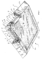
- FIG. 1 a first light box 1 according to the present invention is shown.
- the light box 1 comprises, enclosed in an external frame 2, an optical cavity 3 of a square shape, described in more detail below, and four elongated light sources 4, arranged at each side edge of the square optical cavity 3.
- each light source 4 comprises a parabolic reflector 41 and a fluorescent tube 42 arranged at the focus of the parabolic reflector 41 by means of holders 43, so that the light from the fluorescent tube 42 is directed into the optical cavity 3 essentially parallel to its major faces 5 and 6 (fig. 2).
- parabolic reflector 41 has at its base a portion 44 shaped as a dove-tail. This provision allows, in a per se known manner, to deflect those light rays (essentially horizontal to the left in the view of fig. 2) that would otherwise be reflected back into the fluorescent tube 42, thus increasing the efficiency of light source 4.
- ballast 45 for the light source 4 is also shown in figure 2, while the electrical connections of the light box 1 are omitted from the figures for reasons of clarity.
- the light sources 4 may be of whatever type, as far as both the optical means (parabolic reflector 41) and the electro-optical means (fluorescent tube 42) are concerned.
- a row of LEDs or an arrangement of a single LED and an auxiliary light guide as disclosed in the above cited EP 0 377 309 A2 may be substituted for each light source 4.
- Frame 2 advantageously comprises a supporting inner profile 21 for attachment of the light sources 4 and the major faces 5, 6 of the light guide 1.
- Supporting inner profile 21 also has spaces 22 for insertion of a hanging hook or similar means for attachment of the light box 1 to a ceiling for use as a luminaire, and an external cover 23 that may, as shown in figs. 1 and 2, be inclined so that the frame 2 converges in a direction from the back to the front of the luminaire and gives the latter a pyramid shaped for aesthetical reasons.
- Frame 2 is moreover provided with a bottom flap 24 pivoted to the external cover 23 at hinge 25, so as to allow access to fluorescent tubes 42, electrical wiring and ballast 45 for maintenance and replacement.
- Flap 24 moreover is used to aid in holding in place the first or front major face 5 of the light box.
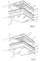
- the first or front face 5 of the optical cavity 3 comprises a micro-structured transparent material 51 to reflect part of the light from light sources 4 back into the optical cavity 3, and to refract part of the light from light sources 4 so as to be emitted out of the light box 1.
- the micro-structured transparent material 51 of the first major face 5 comprises a plurality of portions (four portions 51a-51d being shown in the embodiment of fig. 1), so arranged that the micro-structures of adjacent portions are not parallel to each other.
- each portion 51a-51d of micro-structured transparent material 51 of the first major face 5 is arranged with its micro-structures essentially perpendicular to an adjacent edge of the light box, i.e. essentially perpendicular to the adjacent elongated light source 4.
- the micro-structured transparent material 51 of the first major face 5 is arranged with the micro-structures facing away from the optical cavity 2, (i.e. towards the bottom in the figures).
- a particularly suited micro-structured transparent material is that commercially available as ScotchTM Optical Lighting Film 2301 from 3M Company.
- the portions 51a-51d of micro-structured transparent material 51 are supported by a first sheet 52 of a supporting transparent material, such as a polycarbonate.
- either of the two supporting transparent sheets 52 and 53 may be dispensed with, or even both of them if a self-supporting micro-structured transparent material 51 is used.
- the portions 51a-51d may be adhered to supporting transparent sheet 52 by a transparent adhesive, such as a pressure sensitive adhesive. However, to avoid any adverse effects on the optical performance of the micro-structured transparent material 51, the portions 51a-51d are preferably not attached over their whole surfaces to the supporting transparent sheet 52.
- portions 51a-51d are cut to form a square of a slightly smaller area than the supporting transparent sheets 52 and 53, and the latter are then fixed together (with the portions 51a-51d sandwiched between them) by a peripheral frame of double-sided adhesive tape 54 located between the sheets.
- a particularly suited double-sided adhesive tape 54 is that commercially available as VHBTM Tape from 3M Company.
- Fig. 3 further shows two strips of adhesive tape 55 arranged along the diagonals of front face 5, that is along the adjacent sides of adjacent portions 51a-b, b-c, c-d, d-a of micro-structured transparent material 51.
- such adhesive tape 55 also improves the appearance of the light box 1 by hiding the trimmed edges of each portion 51a-d.
- a particularly suited adhesive tape is that commercially available as AccentrimTM from 3M Company.
- the adjacent portions 51a-b, b-c, c-d, d-a of micro-structured transparent material 51 may be attached to each other on the thickness sides by a transparent adhesive.
- a peripheral frame of suitable optical film 56 may be applied as shown in figs. 1 and 3.
- the optical film may, for example, be the silver dot printed adhesive film available for use as an anti-glare band on car windscreens.
- Optical film 56 may of course be dispensed with, for example by having the pivoting flap 25 of frame 2 extend to a greater degree towards the centre of the light box 1 so as to hide the double-sided adhesive 54.
- a graphics film 57 extends over the whole of the first major face 5.
- a film having a pattern providing a rice paper effect is used, the uniformity of luminosity/illumination of the front face 5 will be further improved, as will the appearance of the light box 1 especially when the light sources 4 are off.
- a particularly suited graphics film 56 is one of the series FasaraTM Glass Decorative Films, commercially available from 3M Company, most preferably the "Sagano" version, product number SH2PT SA.
- the second major face or rear face 6 is designed so as to reflect the light from light sources 4 striking on it back into the optical cavity 3, thus co-operating with the front face 5 in guiding the light within the optical cavity 3.
- the second major or rear face 6 is partly specularly reflective and partly diffusively reflective, so that the angles of the light rays may be partly deviated to a direction allowing them to be emitted from the front face 5.
- the rear face 6 comprises a specularly reflective substrate 61 bearing a plurality of diffusely reflective elements 62, e.g. silk-screen printed white paint dots.
- the diffusely reflective elements 62 comprise, in particular, a plurality of rows of dots parallel to the perimeter of the light guide, that is forming squares, spaced apart by a decreasing distance from the perimeter of the light box 1 towards its center.
- the predetermined configuration of diffusely reflective elements 62 is obtained by applying the principles disclosed in WO 02/23084 .
- back face 6 comprises a sheet of dot printed 3MTM Radiant Mirror Film laminated onto an aluminum sheet.
- front and rear faces 5, 6 as disclosed above form an optical cavity or light guide, whereby light from the light sources 4 is transported along the light box 1 and emitted through its front face 5.
- parabolic reflectors 5 will also act as reflecting sides of the optical cavity 3, by reflecting back within the optical cavity 3 any light rays from one of the other three light sources 4 that failed to exit the light box 1 through the front face 8.
- the arrangement of the elongated light sources 4 at opposite edges of the light box 1, in co-operation with the use of more portions 51a-51d of prismatic transparent material 51, with their micro-structures not parallel to each other, allows the design of the light box 1 to be optimized as to uniformity of luminosity/illumination, as well as to control of glare from a ceiling luminaire.
- FIG. 6 an embodiment wherein the major faces 5, 6 of the light box are rectangular is shown in a diagrammatical view.
- the portions 51e-h of micro-structured transparent material 51 are four equal rectangles each at a corner of the light box 1.
- a light source 4 extends for half of each edge of the light box 1.
- the prismatic micro-structures of adjacent pairs of portions of material 51 are not parallel to each other, and in each portion they are arranged perpendicular to the edge of the light box 1 where a light source 4 is arranged.
- micro-structured transparent material 51 are three equal isosceles triangles, each having a side extending along an edge of the light box 1, where a light source 4 is arranged.
- the prismatic micro-structures of the various portions of material 51 are not parallel to each other, and are arranged perpendicular to the edge of the light box 1, and thus to a light source 4.
- FIG. 8 an embodiment wherein the major faces 5, 6 of the light box are hexagons is shown in a diagrammatical view.
- the portions 511-q of micro-structured transparent material 51 are six equal equilateral triangles, each having a side extending along an edge of the light box 1, where a light source 4 is arranged.
- Light sources 4 have been labeled 41-q after the portion 511-q of micro-structured transparent material they are adjacent to.
- the prismatic micro-structures of adjacent pairs of portions of material 51 are not parallel to each other, and in each portion they are arranged perpendicular to the adjacent edge of the light box 1, and thus to a light source 4.
- Light sources 4m and 4p adjacent to portions 51m and 51p of the micro-structured transparent material 5 are shown in phantom to illustrate that they are optional, insofar as a lesser degree of luminosity/illumination uniformity may be acceptable.
- a light source 4 at each edge of light box 1 the light sources 4 being controlled in groups.
- a first switch (not shown) may control light sources 4m and 4p, while a second switch (not shown) may control light sources 41, 4n, 4o, 4q.
- both switches or the second switch only may be closed to power the respective light sources 4 for lighting purposes, while the first switch only may be closed to power light sources 4m and 4p for safety luminous/lighting purposes.
- the embodiments disclosed above are mere examples of various embodiments of a light source according to the present invention.
- the major faces 5, 6 of the light box may be shaped as a regular polygon of any number of sides.
- the portions of micro-structured transparent material 51 will then be isosceles or equilateral triangles, each having a side extending along an edge of the light box 1.
- a preferred use of the light box 1 according to the invention is as a ceiling luminaire.
- frame 2 shall preferably be a parallelepiped instead of pyramidal.
- a light box 1 may of course be made also as a wall lamp, a desk lamp, a floor lamp, etc. by providing for a suitable support.
- a light box 1 according to the invention may also be used e.g. for luminous purposes only, e.g. for signs, advertisement, and decoration.
- Prototypes of light boxes according to the invention have been prepared and tested.
- the exemplary materials listed above were used for the various components of the front face 5 and of the rear face 6.
- the light boxes so constructed exhibited photometric curves of the type shown in fig. 9, in which the curves 71 and 72 represent luminance in cd/klm along the planes 0/180° and 90/270° respectively. It will be seen that the curves 71 and 72 are essentially equal to one another. Moreover, both curves 71 and 72 are contained within 60° with respect to the vertical, that is the conventional limit angle to avoid glare.
- the isolux diagrams were of the form shown in fig. 10, where each of the areas 81', 82' and 83' represents a different lux value. It will be seen that the different areas are all highly symmetric. In practice, the symmetry will be affected (to a greater or lesser extent) by the light output of any neighbouring light boxes.
- the efficiency of the light boxes was within the range 65-75%.
- the light box 1 according to the present invention may be appropriately employed as a ceiling luminaire without any regard as to where a working site, such as a desk, and especially a computer display, will be located below it, in that a suitable glare-free illumination can be provided within the whole footprint of the light box 1.
Priority Applications (3)
| Application Number | Priority Date | Filing Date | Title |
|---|---|---|---|
| EP04076121A EP1586813A1 (de) | 2004-04-16 | 2004-04-16 | Leuchtkasten |
| EP05729222A EP1740880A1 (de) | 2004-04-16 | 2005-03-14 | Leuchttransparent |
| PCT/US2005/008573 WO2005106321A1 (en) | 2004-04-16 | 2005-03-14 | Light box |
Applications Claiming Priority (1)
| Application Number | Priority Date | Filing Date | Title |
|---|---|---|---|
| EP04076121A EP1586813A1 (de) | 2004-04-16 | 2004-04-16 | Leuchtkasten |
Publications (1)
| Publication Number | Publication Date |
|---|---|
| EP1586813A1 true EP1586813A1 (de) | 2005-10-19 |
Family
ID=34928149
Family Applications (2)
| Application Number | Title | Priority Date | Filing Date |
|---|---|---|---|
| EP04076121A Withdrawn EP1586813A1 (de) | 2004-04-16 | 2004-04-16 | Leuchtkasten |
| EP05729222A Withdrawn EP1740880A1 (de) | 2004-04-16 | 2005-03-14 | Leuchttransparent |
Family Applications After (1)
| Application Number | Title | Priority Date | Filing Date |
|---|---|---|---|
| EP05729222A Withdrawn EP1740880A1 (de) | 2004-04-16 | 2005-03-14 | Leuchttransparent |
Country Status (2)
| Country | Link |
|---|---|
| EP (2) | EP1586813A1 (de) |
| WO (1) | WO2005106321A1 (de) |
Cited By (10)
| Publication number | Priority date | Publication date | Assignee | Title |
|---|---|---|---|---|
| EP1681508A2 (de) * | 2005-01-12 | 2006-07-19 | Manfred Grimm | Deckeneinbauleuchte |
| WO2011039272A1 (de) * | 2009-09-29 | 2011-04-07 | Zumtobel Lighting Gmbh | Beleuchtungsanordnung mit lichtbeeinflussungselement |
| EP2312205A1 (de) * | 2009-10-16 | 2011-04-20 | RIDI Leuchten GmbH | Leuchte |
| WO2012056352A1 (en) * | 2010-10-28 | 2012-05-03 | Koninklijke Philips Electronics N.V. | Illumination device, luminaire and lighting system |
| WO2013034152A1 (de) * | 2011-09-09 | 2013-03-14 | Herbert Waldmann Gmbh & Co. Kg | Leuchte mit folie zur veränderung der abstrahlcharakteristik |
| CN104728687A (zh) * | 2013-12-24 | 2015-06-24 | 深圳市海洋王照明工程有限公司 | 灯具 |
| US9383075B2 (en) | 2011-02-22 | 2016-07-05 | Koninklijke Philips N.V. | Collimator comprising a prismatic layer stack, and lighting unit comprising such a collimator |
| US9632326B2 (en) | 2010-10-28 | 2017-04-25 | Philips Lighting Holding B.V. | Collimator comprising a prismatic layer stack, and lighting unit comprising such collimator |
| EP2844908B1 (de) * | 2012-04-30 | 2018-03-07 | SnapTrack, Inc. | Mehrstrahlige lichtmaschine |
| WO2018081182A1 (en) * | 2016-10-24 | 2018-05-03 | Ameritech Llc | Luminaire including light emitting diodes and having improved energy-efficiency |
Citations (13)
| Publication number | Priority date | Publication date | Assignee | Title |
|---|---|---|---|---|
| FR722673A (fr) * | 1931-09-05 | 1932-03-23 | Holophane Sa | Appareil d'éclairage utilisant des sources lumineuses rectilignes |
| US2050429A (en) * | 1932-07-01 | 1936-08-11 | Holophane Co Inc | Light mixing apparatus |
| US3209137A (en) * | 1963-04-29 | 1965-09-28 | K S H Plastics Inc | Luminous ceiling |
| US4462068A (en) * | 1982-06-24 | 1984-07-24 | Manville Service Corporation | Luminaire with improved lens structure |
| EP0293182A2 (de) | 1987-05-26 | 1988-11-30 | Minnesota Mining And Manufacturing Company | Beleuchtungseinrichtung für rechtwinkligen Lichtaustritt |
| EP0308828A2 (de) | 1987-09-19 | 1989-03-29 | Canon Kabushiki Kaisha | Leuchte und diese verwendender Anzeigeschirm |
| EP0377309A2 (de) | 1989-01-03 | 1990-07-11 | Minnesota Mining And Manufacturing Company | Hinten beleuchtete Anzeigevorrichtung |
| EP0490279A2 (de) | 1990-12-08 | 1992-06-17 | Minnesota Mining And Manufacturing Company | Leuchtkasten |
| WO1994029765A1 (en) | 1993-06-08 | 1994-12-22 | Minnesota Mining And Manufacturing Company | Liquid crystal display with enhanced brightness |
| US5530628A (en) * | 1993-04-05 | 1996-06-25 | Peerless Lighting Corporation | Task light |
| GB2310525A (en) | 1996-02-24 | 1997-08-27 | Ronnie Revell | Illuminated display device |
| WO2001071248A1 (en) | 2000-03-16 | 2001-09-27 | 3M Innovative Properties Company | Light guides suitable for illuminated displays |
| WO2002023084A1 (en) | 2000-09-15 | 2002-03-21 | 3M Innovative Properties Company | Light extractor for a light guide lamp |
Family Cites Families (1)
| Publication number | Priority date | Publication date | Assignee | Title |
|---|---|---|---|---|
| JP3362900B2 (ja) * | 1993-03-09 | 2003-01-07 | 富士通株式会社 | 面発光装置 |
-
2004
- 2004-04-16 EP EP04076121A patent/EP1586813A1/de not_active Withdrawn
-
2005
- 2005-03-14 WO PCT/US2005/008573 patent/WO2005106321A1/en active Application Filing
- 2005-03-14 EP EP05729222A patent/EP1740880A1/de not_active Withdrawn
Patent Citations (13)
| Publication number | Priority date | Publication date | Assignee | Title |
|---|---|---|---|---|
| FR722673A (fr) * | 1931-09-05 | 1932-03-23 | Holophane Sa | Appareil d'éclairage utilisant des sources lumineuses rectilignes |
| US2050429A (en) * | 1932-07-01 | 1936-08-11 | Holophane Co Inc | Light mixing apparatus |
| US3209137A (en) * | 1963-04-29 | 1965-09-28 | K S H Plastics Inc | Luminous ceiling |
| US4462068A (en) * | 1982-06-24 | 1984-07-24 | Manville Service Corporation | Luminaire with improved lens structure |
| EP0293182A2 (de) | 1987-05-26 | 1988-11-30 | Minnesota Mining And Manufacturing Company | Beleuchtungseinrichtung für rechtwinkligen Lichtaustritt |
| EP0308828A2 (de) | 1987-09-19 | 1989-03-29 | Canon Kabushiki Kaisha | Leuchte und diese verwendender Anzeigeschirm |
| EP0377309A2 (de) | 1989-01-03 | 1990-07-11 | Minnesota Mining And Manufacturing Company | Hinten beleuchtete Anzeigevorrichtung |
| EP0490279A2 (de) | 1990-12-08 | 1992-06-17 | Minnesota Mining And Manufacturing Company | Leuchtkasten |
| US5530628A (en) * | 1993-04-05 | 1996-06-25 | Peerless Lighting Corporation | Task light |
| WO1994029765A1 (en) | 1993-06-08 | 1994-12-22 | Minnesota Mining And Manufacturing Company | Liquid crystal display with enhanced brightness |
| GB2310525A (en) | 1996-02-24 | 1997-08-27 | Ronnie Revell | Illuminated display device |
| WO2001071248A1 (en) | 2000-03-16 | 2001-09-27 | 3M Innovative Properties Company | Light guides suitable for illuminated displays |
| WO2002023084A1 (en) | 2000-09-15 | 2002-03-21 | 3M Innovative Properties Company | Light extractor for a light guide lamp |
Non-Patent Citations (1)
| Title |
|---|
| Thin Light Box by Minnesota Mining and Manufacturing Company, March 1990 (St.Paul Minnesota, USA) |
Cited By (19)
| Publication number | Priority date | Publication date | Assignee | Title |
|---|---|---|---|---|
| EP1681508A2 (de) * | 2005-01-12 | 2006-07-19 | Manfred Grimm | Deckeneinbauleuchte |
| EP1681508A3 (de) * | 2005-01-12 | 2006-09-20 | Manfred Grimm | Deckeneinbauleuchte |
| WO2011039272A1 (de) * | 2009-09-29 | 2011-04-07 | Zumtobel Lighting Gmbh | Beleuchtungsanordnung mit lichtbeeinflussungselement |
| EP2312205A1 (de) * | 2009-10-16 | 2011-04-20 | RIDI Leuchten GmbH | Leuchte |
| RU2606946C2 (ru) * | 2010-10-28 | 2017-01-10 | Филипс Лайтинг Холдинг Б.В. | Осветительное устройство, светильник и осветительная система |
| US9279568B2 (en) | 2010-10-28 | 2016-03-08 | Koninklijke Philips N.V. | Illumination device, luminaire and lighting system |
| CN103154782A (zh) * | 2010-10-28 | 2013-06-12 | 皇家飞利浦电子股份有限公司 | 光照装置、照明器以及照明系统 |
| US9632326B2 (en) | 2010-10-28 | 2017-04-25 | Philips Lighting Holding B.V. | Collimator comprising a prismatic layer stack, and lighting unit comprising such collimator |
| WO2012056352A1 (en) * | 2010-10-28 | 2012-05-03 | Koninklijke Philips Electronics N.V. | Illumination device, luminaire and lighting system |
| CN103154782B (zh) * | 2010-10-28 | 2015-09-30 | 皇家飞利浦电子股份有限公司 | 光照装置、照明器以及照明系统 |
| US9383075B2 (en) | 2011-02-22 | 2016-07-05 | Koninklijke Philips N.V. | Collimator comprising a prismatic layer stack, and lighting unit comprising such a collimator |
| WO2013034152A1 (de) * | 2011-09-09 | 2013-03-14 | Herbert Waldmann Gmbh & Co. Kg | Leuchte mit folie zur veränderung der abstrahlcharakteristik |
| CN103782089B (zh) * | 2011-09-09 | 2017-02-15 | 赫伯特沃尔德曼两合公司 | 带有照射特征改变膜的灯 |
| CN103782089A (zh) * | 2011-09-09 | 2014-05-07 | 赫伯特沃尔德曼两合公司 | 带有照射特征改变膜的灯 |
| US9746169B2 (en) | 2011-09-09 | 2017-08-29 | Herbert Waldmann Gmbh & Co. Kg | Light with a film for altering the radiation characteristics |
| EP2844908B1 (de) * | 2012-04-30 | 2018-03-07 | SnapTrack, Inc. | Mehrstrahlige lichtmaschine |
| CN104728687A (zh) * | 2013-12-24 | 2015-06-24 | 深圳市海洋王照明工程有限公司 | 灯具 |
| CN104728687B (zh) * | 2013-12-24 | 2019-02-05 | 深圳市海洋王照明工程有限公司 | 灯具 |
| WO2018081182A1 (en) * | 2016-10-24 | 2018-05-03 | Ameritech Llc | Luminaire including light emitting diodes and having improved energy-efficiency |
Also Published As
| Publication number | Publication date |
|---|---|
| EP1740880A1 (de) | 2007-01-10 |
| WO2005106321A1 (en) | 2005-11-10 |
Similar Documents
| Publication | Publication Date | Title |
|---|---|---|
| WO2005106321A1 (en) | Light box | |
| US8419236B2 (en) | Light boxes with uniform light distribution | |
| US5542201A (en) | Indirectly illuminated sign | |
| US6308444B1 (en) | Light illuminated display board and lampshade using light refraction and reflection effect of transparent acrylic plastic plates | |
| US20130201690A1 (en) | Illumination device and luminaire | |
| RU2608079C2 (ru) | Светильник со световой пластиной | |
| EP1843084B1 (de) | Teilweise eingebaute Einbauleuchte | |
| US20130182458A1 (en) | Light-emitting device for emitting diffuse light | |
| US9297506B2 (en) | LED-based light fixture | |
| US10774529B2 (en) | Ceiling tile with integrated lighting and ceiling system | |
| CN100417353C (zh) | 文化遗产陈列用陈列柜的照明装置 | |
| US7077536B2 (en) | Double-sided edge lighting-type display light box | |
| CA2474334A1 (en) | Lamps | |
| JPH0514361B2 (de) | ||
| JP2009252447A (ja) | 導光器、照明装置、表示装置 | |
| JP2004302028A (ja) | 表示装置および誘導灯装置 | |
| US8162515B2 (en) | Lighting device | |
| CN220707151U (zh) | 防眩微棱镜板及具有其的灯具 | |
| KR100984191B1 (ko) | 조립식 투명 아크릴 패널 및 이를 이용한 led조명 간판 | |
| JP3391483B2 (ja) | ライトボックス | |
| JP2009110804A (ja) | パネル光源 | |
| WO2010121483A1 (zh) | 灯管灯具 | |
| JP4320233B2 (ja) | 照明型片面看板 | |
| JP2008140000A (ja) | 自動販売機用照明装置およびこれを用いた自動販売機 | |
| DK171286B1 (da) | Reklame- og informationstavle |
Legal Events
| Date | Code | Title | Description |
|---|---|---|---|
| PUAI | Public reference made under article 153(3) epc to a published international application that has entered the european phase |
Free format text: ORIGINAL CODE: 0009012 |
|
| AK | Designated contracting states |
Kind code of ref document: A1 Designated state(s): AT BE BG CH CY CZ DE DK EE ES FI FR GB GR HU IE IT LI LU MC NL PL PT RO SE SI SK TR |
|
| AX | Request for extension of the european patent |
Extension state: AL HR LT LV MK |
|
| STAA | Information on the status of an ep patent application or granted ep patent |
Free format text: STATUS: THE APPLICATION IS DEEMED TO BE WITHDRAWN |
|
| 18D | Application deemed to be withdrawn |
Effective date: 20051118 |