EP0487434A1 - Heat exchanger for gas fired boiler, its method of manufacture and boiler having such a heat exchanger - Google Patents
Heat exchanger for gas fired boiler, its method of manufacture and boiler having such a heat exchanger Download PDFInfo
- Publication number
- EP0487434A1 EP0487434A1 EP91420410A EP91420410A EP0487434A1 EP 0487434 A1 EP0487434 A1 EP 0487434A1 EP 91420410 A EP91420410 A EP 91420410A EP 91420410 A EP91420410 A EP 91420410A EP 0487434 A1 EP0487434 A1 EP 0487434A1
- Authority
- EP
- European Patent Office
- Prior art keywords
- chamber
- shell
- hearth
- ferrule
- heating body
- Prior art date
- Legal status (The legal status is an assumption and is not a legal conclusion. Google has not performed a legal analysis and makes no representation as to the accuracy of the status listed.)
- Granted
Links
Images


Classifications
-
- F—MECHANICAL ENGINEERING; LIGHTING; HEATING; WEAPONS; BLASTING
- F24—HEATING; RANGES; VENTILATING
- F24H—FLUID HEATERS, e.g. WATER OR AIR HEATERS, HAVING HEAT-GENERATING MEANS, e.g. HEAT PUMPS, IN GENERAL
- F24H9/00—Details
- F24H9/0005—Details for water heaters
- F24H9/0036—Dispositions against condensation of combustion products
-
- F—MECHANICAL ENGINEERING; LIGHTING; HEATING; WEAPONS; BLASTING
- F24—HEATING; RANGES; VENTILATING
- F24H—FLUID HEATERS, e.g. WATER OR AIR HEATERS, HAVING HEAT-GENERATING MEANS, e.g. HEAT PUMPS, IN GENERAL
- F24H1/00—Water heaters, e.g. boilers, continuous-flow heaters or water-storage heaters
- F24H1/22—Water heaters other than continuous-flow or water-storage heaters, e.g. water heaters for central heating
- F24H1/24—Water heaters other than continuous-flow or water-storage heaters, e.g. water heaters for central heating with water mantle surrounding the combustion chamber or chambers
- F24H1/26—Water heaters other than continuous-flow or water-storage heaters, e.g. water heaters for central heating with water mantle surrounding the combustion chamber or chambers the water mantle forming an integral body
- F24H1/28—Water heaters other than continuous-flow or water-storage heaters, e.g. water heaters for central heating with water mantle surrounding the combustion chamber or chambers the water mantle forming an integral body including one or more furnace or fire tubes
- F24H1/287—Water heaters other than continuous-flow or water-storage heaters, e.g. water heaters for central heating with water mantle surrounding the combustion chamber or chambers the water mantle forming an integral body including one or more furnace or fire tubes with the fire tubes arranged in line with the combustion chamber
-
- F—MECHANICAL ENGINEERING; LIGHTING; HEATING; WEAPONS; BLASTING
- F24—HEATING; RANGES; VENTILATING
- F24H—FLUID HEATERS, e.g. WATER OR AIR HEATERS, HAVING HEAT-GENERATING MEANS, e.g. HEAT PUMPS, IN GENERAL
- F24H1/00—Water heaters, e.g. boilers, continuous-flow heaters or water-storage heaters
- F24H1/48—Water heaters for central heating incorporating heaters for domestic water
- F24H1/52—Water heaters for central heating incorporating heaters for domestic water incorporating heat exchangers for domestic water
-
- F—MECHANICAL ENGINEERING; LIGHTING; HEATING; WEAPONS; BLASTING
- F24—HEATING; RANGES; VENTILATING
- F24H—FLUID HEATERS, e.g. WATER OR AIR HEATERS, HAVING HEAT-GENERATING MEANS, e.g. HEAT PUMPS, IN GENERAL
- F24H9/00—Details
- F24H9/14—Arrangements for connecting different sections, e.g. in water heaters
- F24H9/148—Arrangements of boiler components on a frame or within a casing to build the fluid heater, e.g. boiler
Definitions
- the present invention relates to boilers operating from the energy of gas and intended to ensure the rise in temperature of a heat transfer fluid which can be used for various purposes and, more precisely, in a space heating installation and, optionally , for heating domestic hot water.
- the invention relates, more specifically, to a new structure of the heating body intended to equip wall-mounted gas boilers.
- the present invention aims to remedy the above drawbacks by proposing a new structure of the heating body capable of equipping a heating boiler using gas as fuel.
- the object of the invention is to provide a heating body allowing a good transformation efficiency of the energy used to be obtained and the absence of corrosion of the various elements constituting it and responsible for the heat exchange between the gas or smoke circuit and the circulation circuit of the heat transfer fluid.
- Another object of the invention is to offer a new structure of the heating body allowing an industrialization of its manufacturing process.
- Another object of the invention is to propose a manufacturing method for producing a heating body capable of equipping a gas-type boiler.
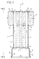
- Fig. 1 is a sectional elevation showing an embodiment of a heating body according to the invention.
- Fig. 2 is a side view taken substantially along line II-II of FIG. 1.
- Fig. 3 is a cross-sectional view taken substantially along line III-III of FIG. 2 .
- Fig. 4 is an exploded sectional view showing the manufacture of a heating body according to the invention.
- Figs. 4A, 4B, 4C are characteristic details illustrating the principle of construction of the heating body in accordance with FIG. 4 .
- Fig. 5 is a view, similar to FIG. 1 , showing a heating body equipped with a coil for the production of domestic hot water.
- Fig. 6 is a front elevation view of a boiler partially equipped with its constituent elements.
- Fig. 7 is a side elevation view taken substantially along lines VII-VII of FIG. 6 .
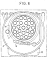
- Fig. 8 is a top view taken substantially along lines VIII-VIII of FIG. 6 .
- Fig. 9 is a sectional view of a characteristic detail illustrated in FIG. 6 .
- Figs. 1 to 3 illustrate an embodiment of a heating body intended to equip a heating boiler using gas as fuel.
- the heating body according to the invention comprises a heat exchanger 1 constituted in the form of a carrier body comprising a series of exchanger tubes 2 , forming a barrel and mounted inside a ferrule 3 having, for example, a circular cross section.
- the peripheral tubes 2 are mounted near the ferrule to allow to remain, with the wall of the latter, a gap of small width whose function will appear more precisely in the following description ( fig. 2 ).
- the exchanger tubes 2 extend substantially parallel to each other, being spaced apart from one another and are fixed, by their base 21 , to a combustion hearth 4 and, by their apex 22 , to a mixing chamber 5 passing through it.
- the ferrule 3 is fixed, by its low end 31 , to the hearth 4 , while its high end 32 carries the chamber 5 .
- the exchanger tubes 2 for example in the number of twenty-two, therefore open inside the hearth 4 and outside the chamber 5 , while passing through the ferrule 3 and the chamber 5 right through.
- the tubes 2 therefore constitute a gas and smoke circulation circuit, represented by the arrows f , coming from the hearth 4 and rising through the tubes to be evacuated outside the chamber 5 to a manifold not shown.
- the walls of the tubes 2 constitute exchange capacities with a circuit for circulation of a heat transfer fluid intended to be contained in the internal volume V of the shell 3 and of the internal volume V1 of the chamber 5 .
- the chamber 5 is advantageously offset relative to the axis of symmetry S of the shell 3 making it possible to provide or delimit, below the chamber 5 and in relation to the shell 3 , a compartment or a housing 6 , shown in broken lines and adapted to receive various functional components of the heating boiler.
- the combustion hearth 4 consists of a support or an envelope 8 delimiting, internally, a volume for receiving a burner, not shown, of the gas type.
- the envelope 8 extends, in relation to the distance of a cap 9 of shape substantially complementary to the envelope, to define between them a lamellar capacity V2 communicating with the internal volume V of the ferrule 3 .
- the casing 8 is therefore intended to receive the feet 21 of the tubes, while the ferrule 3 is fixed to the cover 9 .
- the chamber 5 has, internally, a tubular extension 11 of the shell 3 surrounding the tubes 2 and leaving, with the upper wall 51 of the chamber receiving the vertices 22 of the tubes, an annular passage 12 whose function will appear in the description which follows.
- the tubular extension 11 is provided with a series of openings 13 formed in its lower end part opposite to that high delimiting the annular passage ( 12 ).
- this heating body allows, by means of a burner mounted inside the casing 8 , to ensure combustion in the hearth 4 and to circulate the gases in the direction of the arrows f to the inside the exchanger tubes 2 .
- the combustion gases and fumes are forced to rise inside tubes passing successively through the ferrule 3 and the chamber 5 , before being collected in a collecting box.
- the envelope 8 undergoes a sharp rise in temperature which is transmitted to the blade of fluid occupying the lamellar capacity V2 .
- This fluid capacity rises very quickly in temperature and rises vertically, along the arrows f1 , along the wall of the shell 3 and of the tubular extension 11 .
- This fraction of fluid which has a high temperature, penetrates, through the annular passage 12 , inside the chamber 5 .
- the openings 13 of the extension 11 ensure, with a pressure drop, the passage of a fraction of fluid, from the volume V1 of the chamber 5 to the volume V of the shell 2 .
- Such a fluid transfer represented by the arrows f2 , causes a rapid rise in temperature of the fluid of the volume V of the exchanger.
- the tubes 2 are thus heated by the fluid on their face external to the gas and smoke circulation circuit, to a temperature close to that of the internal faces subjected to the gases and smoke.
- This arrangement eliminates the risk of condensation by temperature heterogeneity on the two faces of the walls which form the interface between the fluid circuit and the gas and smoke circulation circuit.
- the new structure of the heating body described above which is made of a metallic material, makes it possible to limit the risks of corrosion over time and to authorize an industrial manufacturing process described below by way of example.
- the manufacture of such a heating body can be carried out by adapting, on the casing 8 , the cover 9 coming to bear on a flange 81 presented by the lower part of the casing 8 ( fig. 4A ).
- the casing 8 which has, for example, a circular cross section, is provided with bosses 14 ensuring the centering of the cap 9 .
- the ferrule 3 is adapted, by its lower end 31 , on a constriction 91 formed on the cap 9 ( fig. 4B ).
- the exchange tubes 2 are then positioned inside orifices 15 formed in the transverse wall 82 of envelope 8 .
- the upper end 32 of the ferrule 3 is provided with a shoulder 3 a ( FIG. 4C ) intended to receive a lower half-shell 5 a .
- the half-shell 5 has a lower transverse wall includes 52 provided with a central opening bordered by an annular return inflected 53 designed to bear against the shoulder 3 a.
- the half-shell 5 a is capable of receiving, by its junction edge 54 , an upper half-shell 5 b to form the chamber 5 .
- the chamber 5 has a transverse cross section of circular section.
- the vertices 22 of the tubes are then each positioned in holes 16 formed in the high transverse wall 51 of the half-shell 5b .
- the tubes 2 are assembled to the upper half-shell 5b and to the casing 8 , making it possible to support all of the component parts of the heating body.
- the tubes can be assembled by mounting washers or fusible pads 17 , on the feet 21 and the tops 22 of the tubes.
- Such pre-assembly of the heating body, the exchanger of which constitutes a carrier body allows prepositioning of the different parts between them.
- the various stages of the manufacturing process can be carried out in the reverse order to that described.
- the method described above has the advantage of allowing industrial manufacture of the heating body, insofar as it implements usual manufacturing operations.
- the tubular extension 11 can be formed directly by the ferrule 3 or by an insert, as illustrated in FIG. 4 .
- the extension 11 attached is mounted inside the lower half-shell 5 a , prior to the adaptation on the latter of the upper half-shell 5 b .
- the extension 11 is provided, for example at its lower end, with a curved annular rim 11 a coming to bear on the return 5 3 of the half-shell 5 a .
- it can be provided, as illustrated in FIG. 5 , to replace the extension 11 , inside the chamber 5 , by a coil 18 surrounding the tubes 2 and the inlet of which is connected to a cold water supply pipe 19 , while the outlet is connected to a pipe 20 for supplying instant hot water.
- the heating body according to the invention is intended to constitute, in part, a wall-mounted heating boiler 21 , of the gas type, the walls of which, not shown, are shown by broken lines in the drawings.
- the heating body is equipped, in particular, with an expansion tank 22 connected to the chamber 5 and with a return pipe 23 of a heating circuit, on which a circulator 24 is fitted.
- the expansion tank 22 and the circulator 24 are mounted in the compartment or the housing 6 , so as to limit the size of the boiler, as shown more precisely in FIG. 7 .
- the offset of the chamber 5 is produced at the front of the boiler, so that such a compartment 6 is located on the front part of the boiler allowing easy access to the various constituent parts of the boiler.
- the heating body is also equipped with a burner B adapted to the interior of the envelope of the hearth 4 .
- the return pipe 23 of the heating circuit is preferably adapted on the lower part of the chamber 5 , namely on the transverse wall 5 paroi of the lower half-shell 5 a on which the pipe 27 of start of the heating circuit.
- the pipe 20 for supplying instantaneous domestic hot water is fitted on the transverse wall 52
- the pipe 19 for supplying cold water is mounted on the transverse wall 51 of the half-shell.
- the production of domestic hot water can be carried out by using either a coil, as described above, or a storage tank incorporating an exchanger.
- connection of the pipes to the chamber 5 is advantageously carried out by means of a plate 30 , mounted inside the chamber 5 and provided with threads 31 each extending in relation to a hole 32 made in the wall 52 of the chamber.
- Each hole 32 is intended to receive, outside the chamber, a threaded connection 33 intended to cooperate with the corresponding thread 31 and to receive a connection pipe.
- a seal 34 is interposed between the wall 52 of the chamber and a threaded connection.
Abstract
Description
La présente invention concerne les chaudières fonctionnant à partir de l'énergie du gaz et destinées à assurer la montée en température d'un fluide caloporteur pouvant être utilisé à des fins diverses et, plus précisément, dans une installation de chauffage de locaux et, éventuellement, de chauffage de l'eau chaude sanitaire.The present invention relates to boilers operating from the energy of gas and intended to ensure the rise in temperature of a heat transfer fluid which can be used for various purposes and, more precisely, in a space heating installation and, optionally , for heating domestic hot water.
L'invention vise, plus précisément, un nouvelle structure de corps de chauffe destinée à équiper des chaudières à gaz du type mural.The invention relates, more specifically, to a new structure of the heating body intended to equip wall-mounted gas boilers.
Pour assumer la fonction de chauffage d'un fluide caloporteur, l'art antérieur a déjà proposé un grand nombre de solutions techniques pour réaliser des chaudières murales fonctionnant à partir de l'énergie gaz.To assume the heating function of a heat transfer fluid, the prior art has already proposed a large number of technical solutions for producing wall-mounted boilers operating from gas energy.
De nombreuses solutions techniques présentent des inconvénients tenant au mauvais rendement de combustion et à un échange thermique insatisfaisant, entre le foyer de combustion et le fluide caloporteur.Many technical solutions have drawbacks due to poor combustion efficiency and an unsatisfactory heat exchange between the combustion hearth and the heat transfer fluid.
Dans de nombreux cas, également, les chaudières connues présentent l'inconvénient de provoquer, en certains points au moins de leur structure, des oxydations conduisant à la détérioration de certains éléments constitutifs du corps de chauffe. De telles oxydations naissent, en général, d'une hétérogénéité ou mauvaise répartition des températures internes entre deux faces d'un matériau constituant l'interface entre deux circuits de circulation différents, savoir, celui du fluide caloporteur et celui des gaz ou fumées résultant de la combustion.In many cases, too, known boilers have the drawback of causing, at certain points at least in their structure, oxidations leading to the deterioration of certain constituent elements of the heating body. Such oxidations arise, in general, from heterogeneity or poor distribution of internal temperatures between two faces of a material constituting the interface between two different circulation circuits, namely, that of the heat transfer fluid and that of the gases or fumes resulting from combustion.
Par ailleurs, il apparaît que la structure de tels coprs de chauffe interdit une industrialisation de leur procédé de fabrication.Furthermore, it appears that the structure of such heating bodies prevents industrialization of their manufacturing process.
La présente invention vise à remédier aux inconvénients ci-dessus en proposant une nouvelle structure de corps de chauffe susceptible d'équiper une chaudière de chauffage utilisant le gaz comme combustible.The present invention aims to remedy the above drawbacks by proposing a new structure of the heating body capable of equipping a heating boiler using gas as fuel.
L'objet de l'invention est de proposer un corps de chauffe permettant l'obtention d'un bon rendement de transformation de l'énergie utilisée et l'absence de corrosion des divers éléments le constituant et responsables de l'échange thermique entre le circuit de gaz ou fumées et le circuit de circulation du fluide caloporteur.The object of the invention is to provide a heating body allowing a good transformation efficiency of the energy used to be obtained and the absence of corrosion of the various elements constituting it and responsible for the heat exchange between the gas or smoke circuit and the circulation circuit of the heat transfer fluid.
Un autre objet de l'invention est d'offrir une nouvelle structure de corps de chauffe permettant une industrialisation de son procédé de fabrication.Another object of the invention is to offer a new structure of the heating body allowing an industrialization of its manufacturing process.
Pour atteindre les buts ci-dessus, le corps de chauffe selon l'invention comporte un foyer destiné à recevoir un brûleur à gaz, une chambre de chauffage, un circuit de circulation des gaz et fumées, un circuit de circulation du fluide caloporteur et un échangeur de chaleur entre ces deux circuits, caractérisé en ce que :
- l'échangeur est constitué sous la forme d'un corps porteur comportant une virole contenant une série de tubes échangeurs fixés, par leur pied, sur le foyer et, par leur sommet, sur la chambre en la traversant, les tubes échangeurs s'ouvrant à l'intérieur du foyer et à l'extérieur de la chambre,
- et en ce que la chambre et le foyer sont montés, respectivement, à l'une des extrémités de la virole.
- the exchanger is constituted in the form of a carrier body comprising a ferrule containing a series of exchanger tubes fixed, by their foot, on the hearth and, by their top, on the chamber while crossing it, the exchanger tubes opening inside the fireplace and outside the room,
- and in that the chamber and the hearth are mounted, respectively, at one of the ends of the ferrule.
Un autre but de l'invention est de proposer un procédé de fabrication pour réaliser un corps de chauffe susceptible d'équiper une chaudière du type à gaz.Another object of the invention is to propose a manufacturing method for producing a heating body capable of equipping a gas-type boiler.
Selon l'invention, le procédé de fabrication comprend les étapes suivantes :
- adapter une virole, par l'une de ses extrémités, sur un foyer pourvu d'orifices,
- positionner, à l'intérieur de chaque orifice ménagé dans le foyer, un pied d'un tube échangeur communiquant avec le foyer et traversant le volume interne de la virole pour déboucher hors de cette dernière,
- monter une demi-coquille inférieure sur l'autre extrémité de la virole,
- adapter une demi-coquille supérieure sur la demi-coquille inférieure pour délimiter une chambre communiquant avec le volume interne de la virole et positionner, à l'intérieur de chaque passage ménagé dans la demi-coquille supérieure, le sommet d'un tube échangeur traversant la chambre pour communiquer avec l'extérieur de la chambre,
- et assembler les tubes à la demi-coquille supérieure et au foyer pour assurer un prémontage du corps de chauffe.
- adapt a ferrule, by one of its ends, to a hearth provided with orifices,
- position, inside each opening in the hearth, one foot of an exchanger tube communicating with the hearth and crossing the internal volume of the shell to open out of the latter,
- mount a lower half-shell on the other end of the ferrule,
- adapt an upper half-shell to the lower half-shell to delimit a chamber communicating with the internal volume of the shell and position, inside each passage formed in the upper half-shell, the top of a through exchanger tube the room to communicate with the outside of the room,
- and assemble the tubes to the upper half-shell and to the hearth to ensure pre-assembly of the heating body.
Diverses autres caractéristiques ressortent de la description faite ci-dessous en référence aux dessins annexés qui montrent, à titre d'exemples non limitatifs, des formes de réalisation de l'objet de l'invention.Various other characteristics will emerge from the description given below with reference to the appended drawings which show, by way of nonlimiting examples, embodiments of the subject of the invention.
La fig. 1 est une coupe-élévation montrant une forme de réalisation d'un corps de chauffe conforme à l'invention. Fig. 1 is a sectional elevation showing an embodiment of a heating body according to the invention.
La fig. 2 est une vue latérale prise sensiblement selon la ligne II-II de la fig. 1. Fig. 2 is a side view taken substantially along line II-II of FIG. 1.
La fig. 3 est une vue en coupe transversale prise sensiblement selon la ligne III-III de la fig. 2. Fig. 3 is a cross-sectional view taken substantially along line III-III of FIG. 2 .
La fig. 4 est une vue en coupe éclatée montrant la fabrication d'un corps de chauffe conforme à l'invention. Fig. 4 is an exploded sectional view showing the manufacture of a heating body according to the invention.
Les fig. 4A, 4B, 4C sont des détails caractéristiques illustrant le principe de construction du corps de chauffe conforme à la fig. 4. Figs. 4A, 4B, 4C are characteristic details illustrating the principle of construction of the heating body in accordance with FIG. 4 .
La fig. 5 est une vue, analogue à la fig. 1, montrant un corps de chauffe équipé d'un serpentin pour la production d'eau chaude sanitaire. Fig. 5 is a view, similar to FIG. 1 , showing a heating body equipped with a coil for the production of domestic hot water.
La fig. 6 est une vue en élévation frontale d'une chaudière en partie équipée de ses éléments constitutifs. Fig. 6 is a front elevation view of a boiler partially equipped with its constituent elements.
La fig. 7 est une vue en élévation latérale prise sensiblement selon les lignes VII-VII de la fig. 6. Fig. 7 is a side elevation view taken substantially along lines VII-VII of FIG. 6 .
La fig. 8 est une vue de dessus prise sensiblement selon les lignes VIII-VIII de la fig. 6. Fig. 8 is a top view taken substantially along lines VIII-VIII of FIG. 6 .
La fig. 9 est une vue en coupe d'un détail caractéristique illustré à la fig. 6. Fig. 9 is a sectional view of a characteristic detail illustrated in FIG. 6 .
Les fig. 1 à 3 illustrent un exemple de réalisation d'un corps de chauffe destiné à équiper une chaudière de chauffage utilisant le gaz comme combustible. Le corps de chauffe selon l'invention comporte un échangeur de chaleur 1 constitué sous la forme d'un corps porteur comprenant une série de tubes échangeurs 2, formant un barillet et montés à l'intérieur d'une virole 3 présentant, par exemple, une section droite transversale circulaire. Figs. 1 to 3 illustrate an embodiment of a heating body intended to equip a heating boiler using gas as fuel. The heating body according to the invention comprises a
De préférence, les tubes 2 périphériques sont montés à proximité de la virole pour laisser subsister, avec la paroi de cette dernière, un intervale de faible largeur dont la fonction apparaîtra plus précisément dans la suite de la description (fig. 2). Les tubes échangeurs 2 s'étendent sensiblement parallèlement entre eux en étant espacés les uns des autres et sont fixés, par leur pied 2₁, sur un foyer de combustion 4 et, par leur sommet 2₂, sur une chambre de mélange 5 en la traversant. La virole 3 est fixée, par son extrémité basse 3₁, sur le foyer 4, tandis que son extrémité haute 3₂ porte la chambre 5.Preferably, the
Les tubes échangeurs 2, par exemple au nombre de vingtdeux, s'ouvrent donc à l'intérieur du foyer 4 et à l'extérieur de la chambre 5, tout en traversant la virole 3 et la chambre 5 de part en part. Les tubes 2 constituent donc un circuit de circulation des gaz et fumées, représentés par les flèches f , provenant du foyer 4 et s'élevant à travers les tubes pour être évacués à l'extérieur de la chambre 5 vers une boîte collectrice non représentée. Les parois des tubes 2 constituent des capacités d'échange avec un circuit de circulation d'un fluide caloporteur destiné à être contenu dans le volume interne V de la virole 3 et du volume interne V₁ de la chambre 5.The
Tel que cela ressort plus précisément de la fig. 2, la chambre 5 est, avantageusement, déportée par rapport à l'axe de symétrie S de la virole 3 permettant de ménager ou de délimiter, en dessous de la chambre 5 et en relation de la virole 3, un compartiment ou un logement 6, représenté en trait interrompu et adapté pour recevoir divers organes fonctionnels constitutifs de la chaudière de chauffage.As shown more precisely in FIG. 2 , the
De préférence, le foyer de combustion 4 est constitué d'un support ou d'une enveloppe 8 délimitant, intérieurement, un volume pour recevoir un brûleur non représenté, du type à gaz. L'enveloppe 8 s'étend, en relation de distance d'une coiffe 9 de forme sensiblement complémentaire à l'enveloppe, pour définir entre elles une capacité lamellaire V₂ communiquant avec le volume interne V de la virole 3. L'enveloppe 8 est donc destinée à recevoir les pieds 2₁ des tubes, tandis que la virole 3 est fixée sur la coiffe 9.Preferably, the
La capacité lamellaire V₂, le volume interne V de la virole 3 et le volume interne V₁ de la chambre 5, qui communiquent entre eux, représentent ainsi un circuit de circulation d'un fluide caloporteur pouvant être prélevé et ramené par l'intermédiaire de tubulures de raccordement.The lamellar capacity V₂ , the internal volume V of the
Dans la variante de réalisation illustrée à la fig. 1, la chambre 5 comporte, intérieurement, un prolongement tubulaire 11 de la virole 3 entourant les tubes 2 et laissant subsister, avec la paroi supérieure 5₁ de la chambre recevant les sommets 2₂ des tubes, un passage annulaire 12 dont la fonction apparaîtra dans la description qui suit. Le prolongement tubulaire 11 est pourvu d'une série d'ouvertures 13 ménagées dans sa partie terminale basse opposée de celle haute délimitant le passage annulaire (12).In the variant embodiment illustrated in FIG. 1 , the
La structure de ce corps de chauffe permet, au moyen d'un brûleur monté à l'intérieur de l'enveloppe 8, d'assurer la combustion dans le foyer 4 et de faire circuler les gaz dans le sens des flèches f à l'intérieur des tubes échangeurs 2. Les gaz et fumées de combustion sont astreints à s'élever à l'intérieur des tubes en traversant, successivement, la virole 3 et la chambre 5, avant d'être recueillis dans une boîte collectrice.The structure of this heating body allows, by means of a burner mounted inside the
L'enveloppe 8 subit une forte montée en température qui est transmise à la lame de fluide occupant la capacité lamellaire V₂. Cette capacité de fluide monte très vite en température et s'élève verticalement, selon les flèches f₁, le long de la paroi de la virole 3 et du prolongement tubulaire 11. Cette fraction de fluide, qui présente une température élevée, pénètre, par le passage annulaire 12, à l'intérieur de la chambre 5. Les ouvertures 13 du prolongement 11 assurent, avec une perte de charge, le passage d'une fraction de fluide, du volume V₁ de la chambre 5 vers le volume V de la virole 2. Un tel transfert de fluide, représenté par les flèches f₂, provoque une montée rapide en température du fluide du volume V de l'échangeur.The
Les tubes 2 sont ainsi chauffés par le fluide sur leur face extérieure au circuit de circulation de gaz et fumées, à une température voisine de celle des faces internes soumises aux gaz et fumées. Cette disposition permet de supprimer les risques de condensation par hétérogénité des températures sur les deux faces des parois qui forment interface entre le circuit de fluide et le circuit de circulation des gaz et fumées. La nouvelle structure du corps de chauffe décrit ci-dessus, qui est réalisé en un matériau métallique, permet de limiter les risques de corrosion dans le temps et d'autoriser un procédé de fabrication industrielle décrit ci-après à titre d'exemple.The
Tel que cela ressort plus précisément des fig. 4 et 4A à 4C, la fabrication d'un tel corps de chauffe peut être réalisée en adaptant, sur l'enveloppe 8, la coiffe 9 venant en appui sur un rebord 8₁ présenté par la partie basse de l'enveloppe 8 (fig. 4A). L'enveloppe 8, qui présente, par exemple, une section droite transversale circulaire, est pourvue de bossages 14 assurant le centrage de la coiffe 9. La virole 3 est adaptée, par son extrémité inférieure 3₁, sur un rétreint 9₁ ménagé sur la coiffe 9 (fig. 4B). Les tubes d'échange 2 sont ensuite positionnés à l'intérieur d'orifices 15 ménagés dans la paroi transversale 8₂ de l'enveloppe 8. L'extrémité haute 3₂ de la virole 3 est pourvue d'un épaulement 3a (fig. 4C) destiné à recevoir une demi-coquille inférieure 5a . A cet effet, la demi-coquille 5a comporte une paroi transversale inférieure 5₂ pourvue d'une ouverture centrale bordée par un retour annulaire infléchi 5₃ conçu pour venir en appui sur l'épaulement 3a . La demi-coquille 5a est apte à recevoir, par son bord de jonction 5₄, une demi-coquille supérieure 5b pour former la chambre 5. A titre d'exemple, la chambre 5 présente une section droite transversale de section circulaire.As can be seen more precisely from FIGS. 4 and 4A to 4C , the manufacture of such a heating body can be carried out by adapting, on the
Les sommets 2₂ des tubes sont alors chacun positionnés dans des trous 16 ménagés dans la paroi transversale haute 5₁ de la demi-coquille 5b . Les tubes 2 sont assemblés à la demi-coquille supérieure 5b et à l'enveloppe 8, permettant de supporter l'ensemble des pièces constitutives du corps de chauffe. L'assemblage des tubes peut être réalisé en montant des rondelles ou des pastilles fusibles 17, sur les pieds 2₁ et les sommets 2₂ des tubes. Un tel prémontage du corps de chauffe, dont l'échangeur constitue un corps porteur, permet un prépositionnement des différentes pièces entre elles. Bien entendu, les différentes étapes du procédé de fabrication peuvent être réalisées dans un ordre inverse de celui décrit.The
Il est, ensuite, procédé à la réalisation d'une soudure entre la coiffe 9 et le rebord 8₁ de l'enveloppe 8, entre l'extrémité inférieure 3₁ de la virole 3 et la coiffe 9, entre la demi-coquille inférieure 5a et l'épaulement 3a porté par la virole et entre les bords 5₄ de jonction des deux demi-coquilles inférieure et supérieure.It is then carried out to produce a weld between the
Le procédé décrit ci-dessus présente l'avantage de permettre une fabrication industrielle du corps de chauffe, dans la mesure où il met en oeuvre des opérations usuelles de fabrication.The method described above has the advantage of allowing industrial manufacture of the heating body, insofar as it implements usual manufacturing operations.
Bien entendu, le prolongement tubulaire 11 peut être formé directement par la virole 3 ou par un élément rapporté, comme cela est illustré à la fig. 4. Dans ce dernier cas, le prolongement 11 rapporté est monté à l'intérieur de la demi-coquille inférieure 5a , préalablement à l'adaptation sur cette dernière de la demi-coquille supérieure 5b . Le prolongement 11 est pourvu, par exemple à son extrémité basse, d'un rebord annulaire incurvé 11a venant en appui sur le retour 5₃ de la demi-coquille 5a . Par ailleurs, il peut être prévu, comme illustré à la fig. 5, de remplacer le prolongement 11, à l'intérieur de la chambre 5, par un serpentin 18 entourant les tubes 2 et dont l'entrée est raccordée à une canalisation d'amenée d'eau froide 19, tandis que la sortie est raccordée à une canalisation 20 de fourniture d'eau chaude instantanée.Of course, the
Tel que cela apparaît plus précisément aux fig. 6 à 8, le corps de chauffe conforme à l'invention est destiné à constituer, en partie, une chaudière de chauffage 21 mural, du type à gaz, dont les parois, non représentées, sont figurées par des traits interrompus sur les dessins. Le corps de chauffe est équipé, notamment, d'un vase d'expansion 22 raccordé à la chambre 5 et d'une canalisation de retour 23 d'un circuit de chauffage, sur laquelle est adapté un circulateur 24. Avantageusement, le vase d'expansion 22 et le circulateur 24 sont montés dans le compartiment ou le logement 6, de manière à limiter l'encombrement de la chaudière, tel que cela ressort plus précisément de la fig. 7. De préférence, le déport de la chambre 5 est réalisé à l'avant de la chaudière, de manière qu'un tel compartiment 6 se trouve sur la partie frontale de la chaudière permettant l'accès aisé aux différents organes constitutifs de la chaudière. Le corps de chauffe est, également, équipé d'un brûleur B adapté à l'intérieur de l'enveloppe du foyer 4.As shown more precisely in Figs. 6 to 8 , the heating body according to the invention is intended to constitute, in part, a wall-mounted
La canalisation de retour 23 du circuit de chauffe est adaptée, de préférence, sur la partie inférieure de la chambre 5, à savoir sur la paroi transversale 5₂ de la demi-coquille inférieure 5a sur laquelle est adaptée, également, la canalisation 27 de départ du circuit de chauffage. Dans l'exemple illustré, la canalisation 20 de fourniture de l'eau chaude sanitaire instantanée est adaptée sur la paroi transversale 5₂, tandis que la canalisation 19 d'amenée d'eau froide est montée sur la paroi transversale 5₁ de la demi-coquille supérieure. Bien entendu, il est à noter que la production d'eau chaude sanitaire peut être réalisée par la mise en oeuvre, soit d'un serpentin, tel que décrit ci-dessus, soit d'un ballon de stockage intégrant un échangeur.The
Tel que cela apparaît plus précisément aux fig. 6 et 9, le raccordement des tubulures à la chambre 5 est réalisé, avantageusement, par l'intermédiaire d'une platine 30, montée à l'intérieur de la chambre 5 et pourvue de taraudages 31 s'étendant chacun en relation d'un trou 32 ménagé dans la paroi 5₂ de la chambre. Chaque trou 32 est destiné à recevoir, extérieurement à la chambre, un raccord fileté 33 destiné à coopérer avec le taraudage 31 correspondant et à recevoir une tubulure de raccordement. Un joint d'étanchéité 34 est interposé entre la paroi 5₂ de la chambre et un raccord fileté.As shown more precisely in Figs. 6 and 9 , the connection of the pipes to the
L'invention n'est pas limitée aux exemples décrits et représentés, car diverses modifications peuvent y être apportées sans sortir de son cadre.The invention is not limited to the examples described and shown, since various modifications can be made thereto without departing from its scope.
Claims (15)
caractérisé en ce que :
characterized in that:
caractérisé en ce qu'il comprend les étapes suivantes :
characterized in that it comprises the following stages:
Applications Claiming Priority (2)
| Application Number | Priority Date | Filing Date | Title |
|---|---|---|---|
| FR9014695 | 1990-11-19 | ||
| FR9014695A FR2669409B1 (en) | 1990-11-19 | 1990-11-19 | BOILER FOR A GAS-TYPE BOILER, MANUFACTURING METHOD THEREOF AND BOILER INCORPORATING SUCH A BOILER. |
Publications (2)
| Publication Number | Publication Date |
|---|---|
| EP0487434A1 true EP0487434A1 (en) | 1992-05-27 |
| EP0487434B1 EP0487434B1 (en) | 1995-02-01 |
Family
ID=9402557
Family Applications (1)
| Application Number | Title | Priority Date | Filing Date |
|---|---|---|---|
| EP19910420410 Expired - Lifetime EP0487434B1 (en) | 1990-11-19 | 1991-11-19 | Heat exchanger for gas fired boiler, its method of manufacture and boiler having such a heat exchanger |
Country Status (3)
| Country | Link |
|---|---|
| EP (1) | EP0487434B1 (en) |
| DE (1) | DE69107178T2 (en) |
| FR (1) | FR2669409B1 (en) |
Families Citing this family (1)
| Publication number | Priority date | Publication date | Assignee | Title |
|---|---|---|---|---|
| CN106813385A (en) * | 2015-12-01 | 2017-06-09 | 南通港华锅炉有限公司 | A kind of hot-water boiler |
Citations (3)
| Publication number | Priority date | Publication date | Assignee | Title |
|---|---|---|---|---|
| CH382203A (en) * | 1961-03-08 | 1964-09-30 | Von Roll Ag | Heat exchanger |
| FR1578895A (en) * | 1968-05-02 | 1969-08-22 | ||
| FR2557677A1 (en) * | 1983-12-30 | 1985-07-05 | Viessmann Hans | Middle and high output range heating boiler |
-
1990
- 1990-11-19 FR FR9014695A patent/FR2669409B1/en not_active Expired - Fee Related
-
1991
- 1991-11-19 DE DE1991607178 patent/DE69107178T2/en not_active Expired - Fee Related
- 1991-11-19 EP EP19910420410 patent/EP0487434B1/en not_active Expired - Lifetime
Patent Citations (3)
| Publication number | Priority date | Publication date | Assignee | Title |
|---|---|---|---|---|
| CH382203A (en) * | 1961-03-08 | 1964-09-30 | Von Roll Ag | Heat exchanger |
| FR1578895A (en) * | 1968-05-02 | 1969-08-22 | ||
| FR2557677A1 (en) * | 1983-12-30 | 1985-07-05 | Viessmann Hans | Middle and high output range heating boiler |
Also Published As
| Publication number | Publication date |
|---|---|
| FR2669409B1 (en) | 1993-03-05 |
| EP0487434B1 (en) | 1995-02-01 |
| DE69107178T2 (en) | 1995-09-07 |
| DE69107178D1 (en) | 1995-03-16 |
| FR2669409A1 (en) | 1992-05-22 |
Similar Documents
| Publication | Publication Date | Title |
|---|---|---|
| CA1141607A (en) | Boiler, particularly for heating system | |
| EP0487434B1 (en) | Heat exchanger for gas fired boiler, its method of manufacture and boiler having such a heat exchanger | |
| EP2251611A1 (en) | Modular element for radiator with heat-transfer fluid and electric radiator made up of at least one such element | |
| FR2915520A1 (en) | Engine e.g. jet engine, assembly arrangement for aircraft, has heat pipe arranging evaporation end mounted on rectifier stage, and condensation end mounted on nacelle wall that radially determines annular fresh air flow channel | |
| EP2251612A1 (en) | Electric radiator with heat-transfer fluid made up of moulded modular elements | |
| EP0329508A1 (en) | Central heating installation with a sanitary hot water circuit | |
| EP0194975A2 (en) | Radiating heating installation | |
| FR2644230A1 (en) | HEATING BALL OF A LIQUID, PARTICULARLY WATER, AND ONE-PIECE COMBUSTION AND HEAT EXCHANGE ASSEMBLY FOR SUCH A BALL | |
| FR2912210A1 (en) | Heat exchanger for condensing boiler, has two coaxial tubular external and internal ferrules forming insert and defining tubular fume conduit with periodic contractions causing deflection of ferrules with radial component | |
| EP0429371B1 (en) | Shell for a boiler for heating with heat-conveying fluid | |
| EP0127881B1 (en) | Hot water generator, in particular a central heating boiler, for solid fuel, especially for burning logs of wood | |
| FR3062465A1 (en) | BOILER WITH IMPROVED YIELD. | |
| FR2800856A1 (en) | VERTICAL TYPE BOILER | |
| FR2475695A1 (en) | Open fireplace heat recuperator - has reservoir containing medium suspended in chimney with heat exchanger | |
| FR2529648A1 (en) | Refractory-hearth boiler. | |
| FR1402699A (en) | Heat generator in particular for the production of hot water | |
| FR2468852A1 (en) | BOILER, ESPECIALLY FOR DOMESTIC HEATING INSTALLATIONS | |
| BE883241A (en) | BOILER, ESPECIALLY FOR DOMESTIC HEATING INSTALLATIONS | |
| CH419520A (en) | Boiler | |
| BE377640A (en) | ||
| FR3125327A1 (en) | Condensation heat exchanger. | |
| FR2751735A1 (en) | CENTRAL HEATING BOILER WITH BURNER FIOUL | |
| BE410582A (en) | ||
| FR2614402A1 (en) | Heating boiler with laminar exchange volumes | |
| FR2583858A1 (en) | High-efficiency solid fuel boiler |
Legal Events
| Date | Code | Title | Description |
|---|---|---|---|
| PUAI | Public reference made under article 153(3) epc to a published international application that has entered the european phase |
Free format text: ORIGINAL CODE: 0009012 |
|
| AK | Designated contracting states |
Kind code of ref document: A1 Designated state(s): DE IT |
|
| 17P | Request for examination filed |
Effective date: 19930211 |
|
| 17Q | First examination report despatched |
Effective date: 19930629 |
|
| GRAA | (expected) grant |
Free format text: ORIGINAL CODE: 0009210 |
|
| AK | Designated contracting states |
Kind code of ref document: B1 Designated state(s): DE IT |
|
| REF | Corresponds to: |
Ref document number: 69107178 Country of ref document: DE Date of ref document: 19950316 |
|
| ITF | It: translation for a ep patent filed |
Owner name: JACOBACCI CASETTA & PERANI S.P.A. |
|
| PLBE | No opposition filed within time limit |
Free format text: ORIGINAL CODE: 0009261 |
|
| STAA | Information on the status of an ep patent application or granted ep patent |
Free format text: STATUS: NO OPPOSITION FILED WITHIN TIME LIMIT |
|
| 26N | No opposition filed | ||
| PGFP | Annual fee paid to national office [announced via postgrant information from national office to epo] |
Ref country code: DE Payment date: 20001114 Year of fee payment: 10 |
|
| PG25 | Lapsed in a contracting state [announced via postgrant information from national office to epo] |
Ref country code: DE Free format text: LAPSE BECAUSE OF NON-PAYMENT OF DUE FEES Effective date: 20020702 |
|
| PG25 | Lapsed in a contracting state [announced via postgrant information from national office to epo] |
Ref country code: IT Free format text: LAPSE BECAUSE OF NON-PAYMENT OF DUE FEES Effective date: 20051119 |