EP0487434A1 - Wärmetauscher für Gaskessel, Herstellungsverfahren dafür und Kessel mit einem solchen Wärmetauscher - Google Patents
Wärmetauscher für Gaskessel, Herstellungsverfahren dafür und Kessel mit einem solchen Wärmetauscher Download PDFInfo
- Publication number
- EP0487434A1 EP0487434A1 EP91420410A EP91420410A EP0487434A1 EP 0487434 A1 EP0487434 A1 EP 0487434A1 EP 91420410 A EP91420410 A EP 91420410A EP 91420410 A EP91420410 A EP 91420410A EP 0487434 A1 EP0487434 A1 EP 0487434A1
- Authority
- EP
- European Patent Office
- Prior art keywords
- chamber
- shell
- hearth
- ferrule
- heating body
- Prior art date
- Legal status (The legal status is an assumption and is not a legal conclusion. Google has not performed a legal analysis and makes no representation as to the accuracy of the status listed.)
- Granted
Links
- 238000004519 manufacturing process Methods 0.000 title claims description 14
- 238000000034 method Methods 0.000 title claims description 9
- 238000010438 heat treatment Methods 0.000 claims abstract description 49
- 239000007789 gas Substances 0.000 claims abstract description 21
- 239000012530 fluid Substances 0.000 claims abstract description 11
- 239000013529 heat transfer fluid Substances 0.000 claims description 10
- 238000002485 combustion reaction Methods 0.000 claims description 8
- XLYOFNOQVPJJNP-UHFFFAOYSA-N water Substances O XLYOFNOQVPJJNP-UHFFFAOYSA-N 0.000 claims description 8
- 239000003517 fume Substances 0.000 claims description 4
- 230000002093 peripheral effect Effects 0.000 claims description 2
- 210000000056 organ Anatomy 0.000 claims 1
- 238000010079 rubber tapping Methods 0.000 claims 1
- 239000000779 smoke Substances 0.000 abstract description 6
- 239000000470 constituent Substances 0.000 description 3
- 208000031968 Cadaver Diseases 0.000 description 2
- 230000007797 corrosion Effects 0.000 description 2
- 238000005260 corrosion Methods 0.000 description 2
- 239000000446 fuel Substances 0.000 description 2
- 230000003647 oxidation Effects 0.000 description 2
- 238000007254 oxidation reaction Methods 0.000 description 2
- 230000006978 adaptation Effects 0.000 description 1
- 239000000567 combustion gas Substances 0.000 description 1
- 230000000295 complement effect Effects 0.000 description 1
- 238000009833 condensation Methods 0.000 description 1
- 230000005494 condensation Effects 0.000 description 1
- 238000010276 construction Methods 0.000 description 1
- 239000002826 coolant Substances 0.000 description 1
- 230000006866 deterioration Effects 0.000 description 1
- 238000009826 distribution Methods 0.000 description 1
- 238000009434 installation Methods 0.000 description 1
- 239000000463 material Substances 0.000 description 1
- 239000007769 metal material Substances 0.000 description 1
- 238000012986 modification Methods 0.000 description 1
- 230000004048 modification Effects 0.000 description 1
- 230000000630 rising effect Effects 0.000 description 1
- 238000003860 storage Methods 0.000 description 1
- 230000009466 transformation Effects 0.000 description 1
Images


Classifications
-
- F—MECHANICAL ENGINEERING; LIGHTING; HEATING; WEAPONS; BLASTING
- F24—HEATING; RANGES; VENTILATING
- F24H—FLUID HEATERS, e.g. WATER OR AIR HEATERS, HAVING HEAT-GENERATING MEANS, e.g. HEAT PUMPS, IN GENERAL
- F24H9/00—Details
- F24H9/0005—Details for water heaters
- F24H9/0036—Dispositions against condensation of combustion products
-
- F—MECHANICAL ENGINEERING; LIGHTING; HEATING; WEAPONS; BLASTING
- F24—HEATING; RANGES; VENTILATING
- F24H—FLUID HEATERS, e.g. WATER OR AIR HEATERS, HAVING HEAT-GENERATING MEANS, e.g. HEAT PUMPS, IN GENERAL
- F24H1/00—Water heaters, e.g. boilers, continuous-flow heaters or water-storage heaters
- F24H1/22—Water heaters other than continuous-flow or water-storage heaters, e.g. water heaters for central heating
- F24H1/24—Water heaters other than continuous-flow or water-storage heaters, e.g. water heaters for central heating with water mantle surrounding the combustion chamber or chambers
- F24H1/26—Water heaters other than continuous-flow or water-storage heaters, e.g. water heaters for central heating with water mantle surrounding the combustion chamber or chambers the water mantle forming an integral body
- F24H1/28—Water heaters other than continuous-flow or water-storage heaters, e.g. water heaters for central heating with water mantle surrounding the combustion chamber or chambers the water mantle forming an integral body including one or more furnace or fire tubes
- F24H1/287—Water heaters other than continuous-flow or water-storage heaters, e.g. water heaters for central heating with water mantle surrounding the combustion chamber or chambers the water mantle forming an integral body including one or more furnace or fire tubes with the fire tubes arranged in line with the combustion chamber
-
- F—MECHANICAL ENGINEERING; LIGHTING; HEATING; WEAPONS; BLASTING
- F24—HEATING; RANGES; VENTILATING
- F24H—FLUID HEATERS, e.g. WATER OR AIR HEATERS, HAVING HEAT-GENERATING MEANS, e.g. HEAT PUMPS, IN GENERAL
- F24H1/00—Water heaters, e.g. boilers, continuous-flow heaters or water-storage heaters
- F24H1/48—Water heaters for central heating incorporating heaters for domestic water
- F24H1/52—Water heaters for central heating incorporating heaters for domestic water incorporating heat exchangers for domestic water
-
- F—MECHANICAL ENGINEERING; LIGHTING; HEATING; WEAPONS; BLASTING
- F24—HEATING; RANGES; VENTILATING
- F24H—FLUID HEATERS, e.g. WATER OR AIR HEATERS, HAVING HEAT-GENERATING MEANS, e.g. HEAT PUMPS, IN GENERAL
- F24H9/00—Details
- F24H9/14—Arrangements for connecting different sections, e.g. in water heaters
- F24H9/148—Arrangements of boiler components on a frame or within a casing to build the fluid heater, e.g. boiler
Definitions
- the present invention relates to boilers operating from the energy of gas and intended to ensure the rise in temperature of a heat transfer fluid which can be used for various purposes and, more precisely, in a space heating installation and, optionally , for heating domestic hot water.
- the invention relates, more specifically, to a new structure of the heating body intended to equip wall-mounted gas boilers.
- the present invention aims to remedy the above drawbacks by proposing a new structure of the heating body capable of equipping a heating boiler using gas as fuel.
- the object of the invention is to provide a heating body allowing a good transformation efficiency of the energy used to be obtained and the absence of corrosion of the various elements constituting it and responsible for the heat exchange between the gas or smoke circuit and the circulation circuit of the heat transfer fluid.
- Another object of the invention is to offer a new structure of the heating body allowing an industrialization of its manufacturing process.
- Another object of the invention is to propose a manufacturing method for producing a heating body capable of equipping a gas-type boiler.
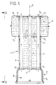
- Fig. 1 is a sectional elevation showing an embodiment of a heating body according to the invention.
- Fig. 2 is a side view taken substantially along line II-II of FIG. 1.
- Fig. 3 is a cross-sectional view taken substantially along line III-III of FIG. 2 .
- Fig. 4 is an exploded sectional view showing the manufacture of a heating body according to the invention.
- Figs. 4A, 4B, 4C are characteristic details illustrating the principle of construction of the heating body in accordance with FIG. 4 .
- Fig. 5 is a view, similar to FIG. 1 , showing a heating body equipped with a coil for the production of domestic hot water.
- Fig. 6 is a front elevation view of a boiler partially equipped with its constituent elements.
- Fig. 7 is a side elevation view taken substantially along lines VII-VII of FIG. 6 .
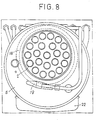
- Fig. 8 is a top view taken substantially along lines VIII-VIII of FIG. 6 .
- Fig. 9 is a sectional view of a characteristic detail illustrated in FIG. 6 .
- Figs. 1 to 3 illustrate an embodiment of a heating body intended to equip a heating boiler using gas as fuel.
- the heating body according to the invention comprises a heat exchanger 1 constituted in the form of a carrier body comprising a series of exchanger tubes 2 , forming a barrel and mounted inside a ferrule 3 having, for example, a circular cross section.
- the peripheral tubes 2 are mounted near the ferrule to allow to remain, with the wall of the latter, a gap of small width whose function will appear more precisely in the following description ( fig. 2 ).
- the exchanger tubes 2 extend substantially parallel to each other, being spaced apart from one another and are fixed, by their base 21 , to a combustion hearth 4 and, by their apex 22 , to a mixing chamber 5 passing through it.
- the ferrule 3 is fixed, by its low end 31 , to the hearth 4 , while its high end 32 carries the chamber 5 .
- the exchanger tubes 2 for example in the number of twenty-two, therefore open inside the hearth 4 and outside the chamber 5 , while passing through the ferrule 3 and the chamber 5 right through.
- the tubes 2 therefore constitute a gas and smoke circulation circuit, represented by the arrows f , coming from the hearth 4 and rising through the tubes to be evacuated outside the chamber 5 to a manifold not shown.
- the walls of the tubes 2 constitute exchange capacities with a circuit for circulation of a heat transfer fluid intended to be contained in the internal volume V of the shell 3 and of the internal volume V1 of the chamber 5 .
- the chamber 5 is advantageously offset relative to the axis of symmetry S of the shell 3 making it possible to provide or delimit, below the chamber 5 and in relation to the shell 3 , a compartment or a housing 6 , shown in broken lines and adapted to receive various functional components of the heating boiler.
- the combustion hearth 4 consists of a support or an envelope 8 delimiting, internally, a volume for receiving a burner, not shown, of the gas type.
- the envelope 8 extends, in relation to the distance of a cap 9 of shape substantially complementary to the envelope, to define between them a lamellar capacity V2 communicating with the internal volume V of the ferrule 3 .
- the casing 8 is therefore intended to receive the feet 21 of the tubes, while the ferrule 3 is fixed to the cover 9 .
- the chamber 5 has, internally, a tubular extension 11 of the shell 3 surrounding the tubes 2 and leaving, with the upper wall 51 of the chamber receiving the vertices 22 of the tubes, an annular passage 12 whose function will appear in the description which follows.
- the tubular extension 11 is provided with a series of openings 13 formed in its lower end part opposite to that high delimiting the annular passage ( 12 ).
- this heating body allows, by means of a burner mounted inside the casing 8 , to ensure combustion in the hearth 4 and to circulate the gases in the direction of the arrows f to the inside the exchanger tubes 2 .
- the combustion gases and fumes are forced to rise inside tubes passing successively through the ferrule 3 and the chamber 5 , before being collected in a collecting box.
- the envelope 8 undergoes a sharp rise in temperature which is transmitted to the blade of fluid occupying the lamellar capacity V2 .
- This fluid capacity rises very quickly in temperature and rises vertically, along the arrows f1 , along the wall of the shell 3 and of the tubular extension 11 .
- This fraction of fluid which has a high temperature, penetrates, through the annular passage 12 , inside the chamber 5 .
- the openings 13 of the extension 11 ensure, with a pressure drop, the passage of a fraction of fluid, from the volume V1 of the chamber 5 to the volume V of the shell 2 .
- Such a fluid transfer represented by the arrows f2 , causes a rapid rise in temperature of the fluid of the volume V of the exchanger.
- the tubes 2 are thus heated by the fluid on their face external to the gas and smoke circulation circuit, to a temperature close to that of the internal faces subjected to the gases and smoke.
- This arrangement eliminates the risk of condensation by temperature heterogeneity on the two faces of the walls which form the interface between the fluid circuit and the gas and smoke circulation circuit.
- the new structure of the heating body described above which is made of a metallic material, makes it possible to limit the risks of corrosion over time and to authorize an industrial manufacturing process described below by way of example.
- the manufacture of such a heating body can be carried out by adapting, on the casing 8 , the cover 9 coming to bear on a flange 81 presented by the lower part of the casing 8 ( fig. 4A ).
- the casing 8 which has, for example, a circular cross section, is provided with bosses 14 ensuring the centering of the cap 9 .
- the ferrule 3 is adapted, by its lower end 31 , on a constriction 91 formed on the cap 9 ( fig. 4B ).
- the exchange tubes 2 are then positioned inside orifices 15 formed in the transverse wall 82 of envelope 8 .
- the upper end 32 of the ferrule 3 is provided with a shoulder 3 a ( FIG. 4C ) intended to receive a lower half-shell 5 a .
- the half-shell 5 has a lower transverse wall includes 52 provided with a central opening bordered by an annular return inflected 53 designed to bear against the shoulder 3 a.
- the half-shell 5 a is capable of receiving, by its junction edge 54 , an upper half-shell 5 b to form the chamber 5 .
- the chamber 5 has a transverse cross section of circular section.
- the vertices 22 of the tubes are then each positioned in holes 16 formed in the high transverse wall 51 of the half-shell 5b .
- the tubes 2 are assembled to the upper half-shell 5b and to the casing 8 , making it possible to support all of the component parts of the heating body.
- the tubes can be assembled by mounting washers or fusible pads 17 , on the feet 21 and the tops 22 of the tubes.
- Such pre-assembly of the heating body, the exchanger of which constitutes a carrier body allows prepositioning of the different parts between them.
- the various stages of the manufacturing process can be carried out in the reverse order to that described.
- the method described above has the advantage of allowing industrial manufacture of the heating body, insofar as it implements usual manufacturing operations.
- the tubular extension 11 can be formed directly by the ferrule 3 or by an insert, as illustrated in FIG. 4 .
- the extension 11 attached is mounted inside the lower half-shell 5 a , prior to the adaptation on the latter of the upper half-shell 5 b .
- the extension 11 is provided, for example at its lower end, with a curved annular rim 11 a coming to bear on the return 5 3 of the half-shell 5 a .
- it can be provided, as illustrated in FIG. 5 , to replace the extension 11 , inside the chamber 5 , by a coil 18 surrounding the tubes 2 and the inlet of which is connected to a cold water supply pipe 19 , while the outlet is connected to a pipe 20 for supplying instant hot water.
- the heating body according to the invention is intended to constitute, in part, a wall-mounted heating boiler 21 , of the gas type, the walls of which, not shown, are shown by broken lines in the drawings.
- the heating body is equipped, in particular, with an expansion tank 22 connected to the chamber 5 and with a return pipe 23 of a heating circuit, on which a circulator 24 is fitted.
- the expansion tank 22 and the circulator 24 are mounted in the compartment or the housing 6 , so as to limit the size of the boiler, as shown more precisely in FIG. 7 .
- the offset of the chamber 5 is produced at the front of the boiler, so that such a compartment 6 is located on the front part of the boiler allowing easy access to the various constituent parts of the boiler.
- the heating body is also equipped with a burner B adapted to the interior of the envelope of the hearth 4 .
- the return pipe 23 of the heating circuit is preferably adapted on the lower part of the chamber 5 , namely on the transverse wall 5 paroi of the lower half-shell 5 a on which the pipe 27 of start of the heating circuit.
- the pipe 20 for supplying instantaneous domestic hot water is fitted on the transverse wall 52
- the pipe 19 for supplying cold water is mounted on the transverse wall 51 of the half-shell.
- the production of domestic hot water can be carried out by using either a coil, as described above, or a storage tank incorporating an exchanger.
- connection of the pipes to the chamber 5 is advantageously carried out by means of a plate 30 , mounted inside the chamber 5 and provided with threads 31 each extending in relation to a hole 32 made in the wall 52 of the chamber.
- Each hole 32 is intended to receive, outside the chamber, a threaded connection 33 intended to cooperate with the corresponding thread 31 and to receive a connection pipe.
- a seal 34 is interposed between the wall 52 of the chamber and a threaded connection.
Landscapes
- Engineering & Computer Science (AREA)
- Physics & Mathematics (AREA)
- Thermal Sciences (AREA)
- Chemical & Material Sciences (AREA)
- Combustion & Propulsion (AREA)
- Mechanical Engineering (AREA)
- General Engineering & Computer Science (AREA)
- Heat-Exchange Devices With Radiators And Conduit Assemblies (AREA)
Applications Claiming Priority (2)
| Application Number | Priority Date | Filing Date | Title |
|---|---|---|---|
| FR9014695A FR2669409B1 (fr) | 1990-11-19 | 1990-11-19 | Corps de chauffe pour chaudiere, du type a gaz, son procede de fabrication et chaudiere incorporant un tel corps de chauffe. |
| FR9014695 | 1990-11-19 |
Publications (2)
| Publication Number | Publication Date |
|---|---|
| EP0487434A1 true EP0487434A1 (de) | 1992-05-27 |
| EP0487434B1 EP0487434B1 (de) | 1995-02-01 |
Family
ID=9402557
Family Applications (1)
| Application Number | Title | Priority Date | Filing Date |
|---|---|---|---|
| EP19910420410 Expired - Lifetime EP0487434B1 (de) | 1990-11-19 | 1991-11-19 | Wärmetauscher für Gaskessel, Herstellungsverfahren dafür und Kessel mit einem solchen Wärmetauscher |
Country Status (3)
| Country | Link |
|---|---|
| EP (1) | EP0487434B1 (de) |
| DE (1) | DE69107178T2 (de) |
| FR (1) | FR2669409B1 (de) |
Families Citing this family (1)
| Publication number | Priority date | Publication date | Assignee | Title |
|---|---|---|---|---|
| CN106813385A (zh) * | 2015-12-01 | 2017-06-09 | 南通港华锅炉有限公司 | 一种热水锅炉 |
Citations (3)
| Publication number | Priority date | Publication date | Assignee | Title |
|---|---|---|---|---|
| CH382203A (de) * | 1961-03-08 | 1964-09-30 | Von Roll Ag | Wärmeaustauscher |
| FR1578895A (de) * | 1968-05-02 | 1969-08-22 | ||
| FR2557677A1 (fr) * | 1983-12-30 | 1985-07-05 | Viessmann Hans | Chaudiere de chauffage a basse temperature, notamment pour les domaines des puissances moyennes et elevees |
-
1990
- 1990-11-19 FR FR9014695A patent/FR2669409B1/fr not_active Expired - Fee Related
-
1991
- 1991-11-19 DE DE1991607178 patent/DE69107178T2/de not_active Expired - Fee Related
- 1991-11-19 EP EP19910420410 patent/EP0487434B1/de not_active Expired - Lifetime
Patent Citations (3)
| Publication number | Priority date | Publication date | Assignee | Title |
|---|---|---|---|---|
| CH382203A (de) * | 1961-03-08 | 1964-09-30 | Von Roll Ag | Wärmeaustauscher |
| FR1578895A (de) * | 1968-05-02 | 1969-08-22 | ||
| FR2557677A1 (fr) * | 1983-12-30 | 1985-07-05 | Viessmann Hans | Chaudiere de chauffage a basse temperature, notamment pour les domaines des puissances moyennes et elevees |
Also Published As
| Publication number | Publication date |
|---|---|
| FR2669409B1 (fr) | 1993-03-05 |
| DE69107178D1 (de) | 1995-03-16 |
| DE69107178T2 (de) | 1995-09-07 |
| FR2669409A1 (fr) | 1992-05-22 |
| EP0487434B1 (de) | 1995-02-01 |
Similar Documents
| Publication | Publication Date | Title |
|---|---|---|
| EP0487434B1 (de) | Wärmetauscher für Gaskessel, Herstellungsverfahren dafür und Kessel mit einem solchen Wärmetauscher | |
| EP2251611A1 (de) | Modulelement für Heizgerät mit Wärmeübertragungsflüssigkeit, und elektrisches Heizgerät, das aus mindestens einem solchen Element besteht | |
| FR2915520A1 (fr) | Ensemble moteur comprenant un ou plusieurs caloducs pour le refroidissement d'un compresseur haute pression | |
| EP2251612A1 (de) | Elektrisches Heizgerät mit Wärmeübertragungsflüssigkeit, das aus gegossenen Modulelementen besteht | |
| FR2912210A1 (fr) | Echangeur thermique pour chaudiere, chaudiere equipee d'un tel echangeur et procede de fabrication d'un tel echangeur | |
| EP0329508A1 (de) | Zentralheizung mit Brauchwasserkreislauf | |
| EP0194975A2 (de) | Strahlungsheizeinrichtung | |
| FR2644230A1 (fr) | Ballon de chauffage d'un liquide, notamment d'eau, et ensemble monobloc de combustion et d'echange de chaleur destine a equiper un tel ballon | |
| EP0429371B1 (de) | Heizkörper für Kessel für Wärmeträgerflüssigkeit | |
| EP0127881B1 (de) | Heisswassererzeuger, insbesondere Zentralheizungskessel für feste Brennstoffe, insbesondere für die Verbrennung von Holzblöcken | |
| FR2800856A1 (fr) | Chaudiere de chauffage du type vertical | |
| FR2582786A1 (fr) | Chauffe-liquide industriel a gaz | |
| FR2975170A1 (fr) | Condenseur et appareils equipes d'un tel condenseur. | |
| FR2475695A1 (fr) | Dispositif recuperateur de chaleur pour cheminees | |
| FR2529648A1 (fr) | Chaudiere a foyer refractaire | |
| FR1402699A (fr) | Générateur de chaleur notamment pour la production d'eau chaude | |
| FR3062465A1 (fr) | Chaudiere a rendement ameliore. | |
| BE883241A (fr) | Chaudiere, notamment pour installations de chauffage domestique | |
| CH419520A (fr) | Chaudière | |
| BE377640A (de) | ||
| FR2751735A1 (fr) | Chaudiere de chauffage central a bruleur fioul | |
| FR3125327A1 (fr) | Echangeur de chaleur à condensation. | |
| BE410582A (de) | ||
| FR2614402A1 (fr) | Chaudiere de chauffage a capacites d'echanges lamellaires | |
| FR2841637A1 (fr) | Chaudiere domestique et corps de chauffe pour une telle chaudiere |
Legal Events
| Date | Code | Title | Description |
|---|---|---|---|
| PUAI | Public reference made under article 153(3) epc to a published international application that has entered the european phase |
Free format text: ORIGINAL CODE: 0009012 |
|
| AK | Designated contracting states |
Kind code of ref document: A1 Designated state(s): DE IT |
|
| 17P | Request for examination filed |
Effective date: 19930211 |
|
| 17Q | First examination report despatched |
Effective date: 19930629 |
|
| GRAA | (expected) grant |
Free format text: ORIGINAL CODE: 0009210 |
|
| AK | Designated contracting states |
Kind code of ref document: B1 Designated state(s): DE IT |
|
| REF | Corresponds to: |
Ref document number: 69107178 Country of ref document: DE Date of ref document: 19950316 |
|
| ITF | It: translation for a ep patent filed | ||
| PLBE | No opposition filed within time limit |
Free format text: ORIGINAL CODE: 0009261 |
|
| STAA | Information on the status of an ep patent application or granted ep patent |
Free format text: STATUS: NO OPPOSITION FILED WITHIN TIME LIMIT |
|
| 26N | No opposition filed | ||
| PGFP | Annual fee paid to national office [announced via postgrant information from national office to epo] |
Ref country code: DE Payment date: 20001114 Year of fee payment: 10 |
|
| PG25 | Lapsed in a contracting state [announced via postgrant information from national office to epo] |
Ref country code: DE Free format text: LAPSE BECAUSE OF NON-PAYMENT OF DUE FEES Effective date: 20020702 |
|
| PG25 | Lapsed in a contracting state [announced via postgrant information from national office to epo] |
Ref country code: IT Free format text: LAPSE BECAUSE OF NON-PAYMENT OF DUE FEES Effective date: 20051119 |