EP0194975A2 - Radiating heating installation - Google Patents
Radiating heating installation Download PDFInfo
- Publication number
- EP0194975A2 EP0194975A2 EP86810126A EP86810126A EP0194975A2 EP 0194975 A2 EP0194975 A2 EP 0194975A2 EP 86810126 A EP86810126 A EP 86810126A EP 86810126 A EP86810126 A EP 86810126A EP 0194975 A2 EP0194975 A2 EP 0194975A2
- Authority
- EP
- European Patent Office
- Prior art keywords
- wall
- primary
- intermediate channel
- channel
- thermal radiation
- Prior art date
- Legal status (The legal status is an assumption and is not a legal conclusion. Google has not performed a legal analysis and makes no representation as to the accuracy of the status listed.)
- Withdrawn
Links
Images


Classifications
-
- F—MECHANICAL ENGINEERING; LIGHTING; HEATING; WEAPONS; BLASTING
- F24—HEATING; RANGES; VENTILATING
- F24H—FLUID HEATERS, e.g. WATER OR AIR HEATERS, HAVING HEAT-GENERATING MEANS, e.g. HEAT PUMPS, IN GENERAL
- F24H1/00—Water heaters, e.g. boilers, continuous-flow heaters or water-storage heaters
- F24H1/18—Water-storage heaters
-
- F—MECHANICAL ENGINEERING; LIGHTING; HEATING; WEAPONS; BLASTING
- F24—HEATING; RANGES; VENTILATING
- F24H—FLUID HEATERS, e.g. WATER OR AIR HEATERS, HAVING HEAT-GENERATING MEANS, e.g. HEAT PUMPS, IN GENERAL
- F24H1/00—Water heaters, e.g. boilers, continuous-flow heaters or water-storage heaters
- F24H1/10—Continuous-flow heaters, i.e. heaters in which heat is generated only while the water is flowing, e.g. with direct contact of the water with the heating medium
- F24H1/12—Continuous-flow heaters, i.e. heaters in which heat is generated only while the water is flowing, e.g. with direct contact of the water with the heating medium in which the water is kept separate from the heating medium
-
- F—MECHANICAL ENGINEERING; LIGHTING; HEATING; WEAPONS; BLASTING
- F24—HEATING; RANGES; VENTILATING
- F24H—FLUID HEATERS, e.g. WATER OR AIR HEATERS, HAVING HEAT-GENERATING MEANS, e.g. HEAT PUMPS, IN GENERAL
- F24H6/00—Combined water and air heaters
Definitions
- the present invention relates to a device for heating a medium by thermal radiation in the visible spectrum emitted by a radiating body brought to high temperature by an energy source.
- an electric heating resistor is immersed in the water to be heated and is in direct or indirect contact with water.
- the object of the present invention is to avoid the drawbacks mentioned above and to make maximum use of the radiation energy produced by a heat source at high temperature.
- the radiation heating device which is the subject of the invention has the characteristics defined in the claims.
- the heating device according to the invention is essentially provided with an intermediate channel which separates the energy source at high temperature of the medium to be heated, in particular water, which allows a free circulation of air in this channel, and which allows the emission and transmission, through this channel, of radiation used for heating indirect of said medium.
- Said intermediate channel comprises at least one inlet opening and one outlet opening which connect this channel to the outside of the heating device and which allow the free circulation of air in this channel.
- Said air inlet and outlet openings will advantageously be associated with means comprising for example a diaphragm making it possible to adjust the inlet and the outlet of the air circulating in this channel.
- the high temperature heat source used in a device according to the invention can be an electric heating resistor which is brought to high temperature without being directly and negatively influenced by the medium to be heated.
- the electric heating resistor can therefore work at its maximum power, while allowing optimum heat transfer.
- the boiler shown in FIG. 1 comprises an electric heating resistor 5 constituting a source of radiant energy at high temperature, which is surrounded by a first cylindrical wall 1 constituting a primary, radiating, coaxial partition formed of a material capable of supporting the high temperature of the radiant heat produced by the heating resistor 5.
- This primary, radiant partition has internal and external faces which are blackened, so that it can act as a black body capable of absorbing this radiant heat on its front face , internal, to heat up as well, and to emit secondary radiation in the visible spectrum.
- These two coaxial partitions 1 and 2 are radially spaced and delimit between them an annular passage forming an intermediate channel 3 which is provided with an inlet opening 7 and an outlet opening 8 communicating with the outside of the device and serving to allow free air circulation in this channel 3, as indicated by arrows in FIG. 1.
- the water tank 4 of the boiler described is delimited by an external insulating wall 6, closed at its two ends, and provided with a cold water inlet 9 and a hot water outlet 10.
- the coaxial partitions 1 and 2 thus delimit the intermediate channel 3 which separates the source of energy at high temperature, constituted by the heating resistor 5, from the water to be heated in the tank 4.
- the boiler shown in FIG. 3 comprises an oil burner which has a flame 15, constitutes a source of radiant energy at high temperature, and is arranged axially in a combustion chamber delimited by a cylindrical wall 11 constituting a primary, radiating partition. , coaxial formed of a material capable of withstanding the high temperature of the flame 15 of the burner.
- This primary, radiant partition 11 has blackened internal and external faces, so that it can act as a black body capable of absorbing on its blackened internal surface the radiant heat emitted by the flame 15, thus heating up, and reemitting radially towards the exterior, from its blackened external surface, secondary radiation in the visible spectrum.
- This first wall 11 constituting a primary, radiating partition used to intercept and re-emit the radiation produced by the flame 15, is surrounded by a second cylindrical wall 12 which constitutes a secondary, coaxial partition formed of a heat conducting material, and which serves to the exchange of heat with the water to be heated contained in a tank 14.
- the two coaxial walls 11 and 12 are spaced radially from each other, serve to delimit between them a vertical annular passage forming an intermediate channel 13 which is provided at its lower end with an air inlet 17 and, at its upper end with an air outlet 18, and allows free circulation of air along this channel 13, as indicated by arrows in FIG. 3.
- the tank 14 of this boiler is delimited by an external insulating wall 16 closed at its two ends, and provided with a tangential cold water inlet 19 and a radial hot water outlet 20 .
- the coaxial walls 11 and 12 thus delimit the intermediate channel 13 which separates the flame 15 from the burner, constituting the source of energy at high temperature, from the water to be heated.
- the heating device according to FIGS. 4 and 5 constitutes a variant similar to that already described according to FIGS. 1 and 2.
- the identical elements thus have the same reference numbers in FIGS. 1.2 and 5.6, and will only be briefly described here.
- the heating device is provided with an electrical resistance composed of a plurality of electrical heating spirals 25, each mounted on a porcelain support and housed respectively in corresponding longitudinal grooves formed at the periphery of a body refractory 22.
- This body 22 is heated to high temperature by these spirals 25 and has an external wall 21, constituting a primary wall used to emit thermal radiation in the visible spectrum and to delimit one side of the intermediate channel 3 for the free circulation of air using the air inlet 7 and outlet 8 openings communicating with the outside of the heating device.
- the intermediate channel 3 is also delimited by a secondary wall 2 whose internal surface receives, through this channel 3, the thermal radiation emitted in the visible spectrum by the primary wall 21, while its external surface is in contact with water to be heated in the tank 4, provided with an external insulating wall 6 and inlet 9 and outlet 10 openings.
- the radiation heating device according to the invention can also be advantageously used for heating water or any other suitable medium, therefore various fluids, liquids or gases, or any solid medium, intended for indirect heating by transmitted thermal radiation. through said intermediate air circulation channel.
- said intermediate air circulation channel comprising in particular said primary, radiant wall associated with said intermediate channel of free air circulation, it becomes possible to carry this wall pri mayor, radiating at a very high temperature allowing it to emit thermal radiation in the visible spectrum, to avoid at the same time any harmful overheating, or indeed undesirable cooling, and thus to ensure prolonged indirect heating by high radiation temperature with high efficiency.
Abstract
Description
La présente invention a pour objet un dispositif de chauffage d'un milieu par rayonnement thermique dans le spectre visible émis par un corps rayonnant porté à haute température par une source d'énergie.The present invention relates to a device for heating a medium by thermal radiation in the visible spectrum emitted by a radiating body brought to high temperature by an energy source.
Dans les systèmes de chauffage actuels, le transfert de chaleur de la source d'énergie au milieu à chauffer s'effectue essentiellement par conduction ou convection.In current heating systems, the transfer of heat from the energy source to the medium to be heated is essentially carried out by conduction or convection.
Ainsi, par exemple, dans les systèmes de chauffage électrique conventionnels pour la production d'eau chaude, une résistance électrique chauffante est immergée dans l'eau à chauffer et se trouve en contact direct ou indirect avec l'eau.Thus, for example, in conventional electric heating systems for the production of hot water, an electric heating resistor is immersed in the water to be heated and is in direct or indirect contact with water.
De même, dans les systèmes de chauffage utilisant des énergies fossiles (bois, charbon, mazout, pétrole, gaz), le transfert de la chaleur de combustion au milieu à chauffer s'effectue essentiellement par conduction et convection.Similarly, in heating systems using fossil fuels (wood, coal, fuel oil, oil, gas), the transfer of combustion heat to the medium to be heated is essentially carried out by conduction and convection.
Il en résulte une mauvaise utilisation de l'énergie produite par rayonnement de la source de chaleur et la température basse du milieu à chauffer influence négativement la chaleur produite par ce rayonnement.This results in improper use of the energy produced by radiation from the heat source and the low temperature of the medium to be heated negatively influences the heat produced by this radiation.
Le but de la présente invention est d'éviter les inconvénients cités ci-dessus et d'utiliser au maximum l'énergie de rayonnement produite par une source de chaleur à haute température.The object of the present invention is to avoid the drawbacks mentioned above and to make maximum use of the radiation energy produced by a heat source at high temperature.
Dans ce but, le dispositif de chauffage par rayonnement faisant l'objet de l'invention présente les caractéristiques définies dans les revendications.To this end, the radiation heating device which is the subject of the invention has the characteristics defined in the claims.
Le dispositif de chauffage selon l'invention est essentiellement muni d'un canal intermédiaire qui sépare la source d'énergie à haute température du milieu à chauffer, notamment l'eau, qui permet une libre circulation d'air dans ce canal, et qui permet l'émission et transmission, à travers ce canal, d'un rayonnement servant au chauffage indirect dudit milieu.The heating device according to the invention is essentially provided with an intermediate channel which separates the energy source at high temperature of the medium to be heated, in particular water, which allows a free circulation of air in this channel, and which allows the emission and transmission, through this channel, of radiation used for heating indirect of said medium.
Ledit canal intermédiaire comprend au moins une ouverture d'entrée et une ouverture de sortie qui relient ce canal à l'extérieur du dispositif de chauffage et qui permettent la libre circulation d'air dans ce canal. Lesdites ouvertures d'entrée et de sortie d'air,seront avantageusement associées à des moyens comprenant par exemple un diaphragme permettant d'ajuster l'entrée et la sortie de l'air circulant dans ce canal.Said intermediate channel comprises at least one inlet opening and one outlet opening which connect this channel to the outside of the heating device and which allow the free circulation of air in this channel. Said air inlet and outlet openings will advantageously be associated with means comprising for example a diaphragm making it possible to adjust the inlet and the outlet of the air circulating in this channel.
La source de chaleur à haute température utilisée dans un dispositif selon l'invention peut être une résistance électrique chauffante qui se trouve portée à haute température sans qu'elle ne soit influencée directement et négativement par le milieu à chauffer. La résistance électrique chauffante peut donc travailler au maximum de sa puissance, tout en permettant un transfert de chaleur optimum.The high temperature heat source used in a device according to the invention can be an electric heating resistor which is brought to high temperature without being directly and negatively influenced by the medium to be heated. The electric heating resistor can therefore work at its maximum power, while allowing optimum heat transfer.
L'invention peut être illustrée par les formes d'exécution d'un dispositif de chauffage par rayonnement selon l'invention qui sont décrites ci-dessous à titre d'exemple à l'aide du dessin annexé.
- La figure 1 du dessin représente une coupe longitudinale schématique (suivant le plan A-A, fig. 2) d'une chaudière électrique pour la production d'eau chaude constituant une première forme d'exécution du dispositif de chauffage de l'invention.
- La figure 2 représente une coupe transversale schématique de cette chaudière (suivant la plan B-B, fig. 1).
- La figure 3 représente une coupe longitudinale schématique (suivant le plan A-A, fig.-4) d'une chaudière à mazout selon une deuxième forme d'exécution du dispositif de chauffage selon l'invention.
- La figure 4 représente une coupe transversale schématique (suivant le plan B-B, fig. 3) de cette chaudière selon cette deuxième forme d'exécution.
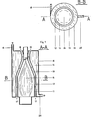
- La figure 5 représente une coupe longitudinale schématique (suivant le plan A-A, fig. 6) d'un dispositif pour le chauffage électrique d'eau selon une autre forme d'exécution de l'invention.
- La figure 6 représente une coupe transversale schématique de la forme d'exécution du dispositif selon fig. 5.
- Figure 1 of the drawing shows a schematic longitudinal section (along the plane AA, Fig. 2) of an electric boiler for the production of hot water constituting a first embodiment of the heating device of the invention.
- Figure 2 shows a schematic cross section of this boiler (on the plane BB, fig. 1).
- Figure 3 shows a schematic longitudinal section (along the plane AA, fig.-4) of an oil boiler according to a second embodiment of the heating device according to the invention.
- Figure 4 shows a cross section diagram tick (according to plan BB, fig. 3) of this boiler according to this second embodiment.
- 5 shows a schematic longitudinal section (along the plane AA, Fig. 6) of a device for the electric heating of water according to another embodiment of the invention.
- FIG. 6 represents a schematic cross section of the embodiment of the device according to FIG. 5.
La chaudière représentée sur la figure 1 comprend une résistance électrique chauffante 5 constituant une source d'énergie rayonnante à haute température, qui est entourée par une première paroi cylindrique 1 constituant une cloison primaire, rayonnante, coaxiale formée d'un matériau capable de supporter la haute température de la chaleur rayonnante produite par la résistance chauffante 5. Cette cloison primaire, rayonnante présente des faces interne et externe qui sont noircies, de manière qu'elle puisse agir comme un corps noir capble d'absorber cette chaleur rayonnante sur sa face avant, interne, de se rechauffer ainsi, et d'émettre un rayonnement secondaire dans le spectre visible. Cette paroi 1 constituant une cloison primaire, rayonnante, servant à capter le rayonnement émis par la résistance chauffante 1, est entourée par une deuxième paroi cylindrique 2 constituant une cloison secondaire, conductrice, coaxiale formée d'un matériau conducteur de chaleur, qui sert à l'échange de chaleur avec l'eau à chauffer, contenue dans un réservoir 4. Ces deux cloisons coaxiales 1 et 2 sont espacées radialement et délimitent entre elles un passage annulaire formant un canal intermédiaire 3 qui est muni d'une ouverture d'entrée 7 et d'une ouverture de sortie 8 communiquant avec l'extérieur du dispositif et servant à permettre une libre circulation d'air dans ce canal 3, comme il est indiqué par des flèches sur la figure 1.The boiler shown in FIG. 1 comprises an
Le réservoir d'eau 4 de la chaudière décrite est délimité par une paroi isolante externe 6, fermé à ses deux extrémités, et muni d'une entrée 9 d'eau froide et d'une sortie 10 d'eau chaude.The
Les cloisons coaxiales 1 et 2 délimitent ainsi le canal intermédiaire 3 qui sépare la source d'énergie à haute température, constituée par la résistance chauffante 5, de l'eau à chauffer dans le réservoir 4.The
Le fonctionnement de la chaudière décrite peut être expliqué de la manière suivante:
- La résistance électrique chauffante 5 est conçue de manière qu'elle puisse être chauffée à.une température élevée de plusieurs centaines de degrés centigrade, et qu'elle puisse ainsi émettre de la chaleur rayonnante dans le spectre visible, dirigée radialement vers l'extérieur en direction de la face noircie, interne de la cloison primaire, rayonnante 1. Cette chaleur rayonnante est ainsi captée et absorbée par la face interne noircie de cette cloison primaire rayonnante 1, qui se réchauffe en conséquence, et émet à son tour un rayonnement secondaire à une température élevée, radialement vers l'extérieur, en direction de la cloison secondaire 2. Cette dernière est ainsi réchauffée indirectement par la chaleur du rayonnement secondaire émis par la cloison primaire, rayonnante à travers le canal intermédiaire 3, capté et absorbé par sa face interne. L'eau dans le
réservoir 4 est ainsi réchauffée indirectement, par l'intermédiaire de la cloison primaire rayonnante 1, du canal intermédiaire 3 à libre circulation d'air, de manière que la température de l'eau n'influence pas directement la résistance chauffante 5 à haute température.
- The
electric heating resistor 5 is designed so that it can be heated to a high temperature of several hundred degrees centigrade, and so that it can emit radiant heat in the visible spectrum, directed radially outwards in direction of the blackened, internal face of the primary,radiating partition 1. This radiant heat is thus captured and absorbed by the blackened internal face of this primaryradiating partition 1, which heats up consequently, and in turn emits secondary radiation to a high temperature, radially outward, in the direction of thesecondary partition 2. The latter is thus indirectly heated by the heat of the secondary radiation emitted by the primary partition, radiating through theintermediate channel 3, captured and absorbed by its face internal. The water in thetank 4 is thus indirectly heated, via the primaryradiating partition 1, of theintermediate channel 3 with free circulation of air, so that the temperature of the water does not directly influence theresistance heating 5 at high temperature.
La chaudière représentée sur la figure 3 comprend un brûleur à mazout qui présente une flamme 15, constitue une source d'énergie rayonnante à haute température, et est disposé axialement dans une chambre de combustion délimitée par une paroi cylindrique 11 constituant une cloison primaire, rayonnante, coaxiale formée d'un matériau capable de résister à la haute température de la flamme 15 du brûleur. Cette cloison primaire, rayonnante 11 présente des faces interne et externe noircies, de manière qu'elle puisse agir comme un corps noir capable d'absorber sur sa surface interne noircie la chaleur rayonnante émise par la flamme 15, se rechauffer ainsi, et reémettre radialement vers l'extérieur, de sa surface externe noircie, un rayonnement secondaire dans le spectre visible. Cette première paroi 11 constituant une cloison primaire, rayonnante servant à intercepter et reémettre le rayonnement produit par la flamme 15, est entourée par une deuxième paroi cylindrique 12 qui constitue une cloison secondaire, coaxiale formée d'un matériau conducteur de chaleur, et qui sert à l'échange de chaleur avec l'eau à chauffer contenue dans un résevoir 14. Les deux parois coaxiales 11 et 12 sont éspacées radialement l'une de l'autre, servent à délimiter entre elles un passage annulaire vertical formant un canal intermédiare 13 qui est muni à son extrémité inférieure d'une entrée d'air 17 et, à son extrémité supérieure d'une sortie d'air 18, et permet une circulation libre d'air le long de ce canal 13, comme il est indiqué par des flèches sur la figure 3. Le réservoir 14 de cette chaudière est délimité par une paroi isolante externe 16 fermée à ses deux extrémités, et munie d'une entrée tangentielle d'eau froide 19 et d'une sortie radiale d'eau chaude 20.The boiler shown in FIG. 3 comprises an oil burner which has a
Les parois coaxiales 11 et 12 délimitent ainsi le canal intermédiaire 13 qui sépare la flamme 15 du brûleur, constituant la source d'énergie à haute température, de l'eau à chauffer.The
Le fonctionnement de cette chaudière à mazout,et en particulier le rôle des parois 11 et 12 délimitant le canal intermédiare 13, correspondent essentiellement à ceux des parois 1 et 2 et du canal 3, comme il a déjà été expliqué par rapport à la chaudière éléctrique selon la figure 1.The operation of this oil-fired boiler, and in particular the role of the
Le dispositif de chauffage selon les figures 4 et 5 constitue une variante analogue à celui déjà décrit selon les figs. 1 et 2. Les éléments identiques portent ainsi les mêmes chiffres de référence dans les figs. 1,2 et 5,6, et ne seront que brièvement décrits ici.The heating device according to FIGS. 4 and 5 constitutes a variant similar to that already described according to FIGS. 1 and 2. The identical elements thus have the same reference numbers in FIGS. 1.2 and 5.6, and will only be briefly described here.
Dans cette variante selon les figs. 5 et 6, le dispositif de chauffage est muni d'une résistance électrique composée d'une pluralité de spirales de chauffe électrique 25, montée chacune sur un support en porcelaine et logées respectivement dans des rainures longitudinales correspondantes menagées à la périphérie d'un corps réfractaire 22. Ce corps 22 est chauffé à haute température par ces spirales 25 et présente une paroi externe 21, constituant une paroi primaire servant à émettre le rayonnement thermique dans le spectre visible et à délimiter un côté du canal intermédiaire 3 pour la circulation libre d'air à l'aide des ouvertures d'entrée 7 et de sortie 8 d'air communiquant avec l'extérieur du dispositif de chauffage. Le canal intermédiare 3 est délimité également par une paroi secondaire 2 dont la surface interne reçoit, à travers ce canal 3, le rayonnement thermique émis dans le spectre visible par la paroi primaire 21, tandis que sa surface externe est au contact de l'eau à chauffer dans le réservoir 4, muni d'une paroi isolante externe 6 et d'ouvertures d'entrée 9 et de sortie 10.In this variant according to figs. 5 and 6, the heating device is provided with an electrical resistance composed of a plurality of
Cette structure et le mode de fonctionnement du dispositif de chauffage sont donc essentiellement analogues à ceux déjà décrits par rapport aux figs. 1 et 2.This structure and the operating mode of the heating device are therefore essentially similar to those already described with respect to FIGS. 1 and 2.
Il est entendu que l'on peut prévoir différentes modifications et variantes du dispositif de chauffage par rayonnement dans le cadre de l'invention. Le dispositif de chauffage par rayonnement selon l'invention peut par ailleurs être utilisé avantageusement pour chauffer de l'eau ou tout autre milieu approprié, donc divers fluides, liquides ou gazeux, ou bien tout milieu solide, destiné au chauffage indirect par rayonnement thermique transmis à travers ledit canal intermédiaire de circulation libre d'air. Ainsi, grâce à la combinaison spéciale telle que prévue conformément à l'invention, comportant notamment ladite paroi primaire, rayonnante associée audit canal intermédiaire de circulation libre d'air, il devient possible de porter cette paroi primaire, rayonnante à une température très élevée lui permettant d'émmettre un rayonnement thermique dans le spectre visible, d'éviter en même temps toute surchauffe nuisible, ou bien un refroidissement indésirable, et d'assurer ainsi un chauffage indirect prolongé par rayonnement à haute température avec un rendement élevé.It is understood that different modifications and variants of the radiation heating device can be provided within the framework of the invention. The radiation heating device according to the invention can also be advantageously used for heating water or any other suitable medium, therefore various fluids, liquids or gases, or any solid medium, intended for indirect heating by transmitted thermal radiation. through said intermediate air circulation channel. Thus, thanks to the special combination as provided in accordance with the invention, comprising in particular said primary, radiant wall associated with said intermediate channel of free air circulation, it becomes possible to carry this wall pri mayor, radiating at a very high temperature allowing it to emit thermal radiation in the visible spectrum, to avoid at the same time any harmful overheating, or indeed undesirable cooling, and thus to ensure prolonged indirect heating by high radiation temperature with high efficiency.
Claims (5)
Applications Claiming Priority (2)
| Application Number | Priority Date | Filing Date | Title |
|---|---|---|---|
| CH1106/85 | 1985-03-12 | ||
| CH110685 | 1985-03-12 |
Publications (2)
| Publication Number | Publication Date |
|---|---|
| EP0194975A2 true EP0194975A2 (en) | 1986-09-17 |
| EP0194975A3 EP0194975A3 (en) | 1988-07-13 |
Family
ID=4202629
Family Applications (1)
| Application Number | Title | Priority Date | Filing Date |
|---|---|---|---|
| EP86810126A Withdrawn EP0194975A3 (en) | 1985-03-12 | 1986-03-12 | Radiating heating installation |
Country Status (1)
| Country | Link |
|---|---|
| EP (1) | EP0194975A3 (en) |
Cited By (7)
| Publication number | Priority date | Publication date | Assignee | Title |
|---|---|---|---|---|
| EP0262263A1 (en) * | 1985-04-04 | 1988-04-06 | van Heel, Joannes Marie | An air heating apparatus |
| EP0374878A2 (en) * | 1988-12-23 | 1990-06-27 | Atwood Industries Inc. | Gas-powered apparatus for producing warm water and for heating an enclosed space |
| US5054108A (en) * | 1987-03-30 | 1991-10-01 | Arnold Gustin | Heater and method for deionized water and other liquids |
| EP0877208A3 (en) * | 1997-05-07 | 2000-07-05 | Dietrich Schröck | Radiating space heating system |
| WO2008043573A1 (en) * | 2006-10-13 | 2008-04-17 | Willis Heating And Plumbing Co Ltd | Water heating apparatus and system |
| WO2015117219A1 (en) * | 2014-02-07 | 2015-08-13 | Sylvain Laberge | Baseboard for use in preheating water |
| WO2019025636A1 (en) * | 2017-08-04 | 2019-02-07 | Dometic Sweden Ab | Heat transfer unit, heating unit and heating apparatus for recreational vehicles, and recreational vehicles |
Citations (3)
| Publication number | Priority date | Publication date | Assignee | Title |
|---|---|---|---|---|
| US2084287A (en) * | 1935-08-29 | 1937-06-15 | Handley Brown Heater Company | Apparatus for heating liquids with fluid fuel |
| US2377785A (en) * | 1943-08-25 | 1945-06-05 | Walter E Hudson | Electric furnace water heater |
| DE1295163B (en) * | 1964-04-04 | 1969-05-14 | Ettling Hermann | Room air heater with domestic water heater |
-
1986
- 1986-03-12 EP EP86810126A patent/EP0194975A3/en not_active Withdrawn
Patent Citations (3)
| Publication number | Priority date | Publication date | Assignee | Title |
|---|---|---|---|---|
| US2084287A (en) * | 1935-08-29 | 1937-06-15 | Handley Brown Heater Company | Apparatus for heating liquids with fluid fuel |
| US2377785A (en) * | 1943-08-25 | 1945-06-05 | Walter E Hudson | Electric furnace water heater |
| DE1295163B (en) * | 1964-04-04 | 1969-05-14 | Ettling Hermann | Room air heater with domestic water heater |
Cited By (8)
| Publication number | Priority date | Publication date | Assignee | Title |
|---|---|---|---|---|
| EP0262263A1 (en) * | 1985-04-04 | 1988-04-06 | van Heel, Joannes Marie | An air heating apparatus |
| US5054108A (en) * | 1987-03-30 | 1991-10-01 | Arnold Gustin | Heater and method for deionized water and other liquids |
| EP0374878A2 (en) * | 1988-12-23 | 1990-06-27 | Atwood Industries Inc. | Gas-powered apparatus for producing warm water and for heating an enclosed space |
| EP0374878A3 (en) * | 1988-12-23 | 1991-02-20 | Atwood Industries Inc. | Gas-powered apparatus for producing warm water and for heating an enclosed space |
| EP0877208A3 (en) * | 1997-05-07 | 2000-07-05 | Dietrich Schröck | Radiating space heating system |
| WO2008043573A1 (en) * | 2006-10-13 | 2008-04-17 | Willis Heating And Plumbing Co Ltd | Water heating apparatus and system |
| WO2015117219A1 (en) * | 2014-02-07 | 2015-08-13 | Sylvain Laberge | Baseboard for use in preheating water |
| WO2019025636A1 (en) * | 2017-08-04 | 2019-02-07 | Dometic Sweden Ab | Heat transfer unit, heating unit and heating apparatus for recreational vehicles, and recreational vehicles |
Also Published As
| Publication number | Publication date |
|---|---|
| EP0194975A3 (en) | 1988-07-13 |
Similar Documents
| Publication | Publication Date | Title |
|---|---|---|
| EP0520913B1 (en) | Heating device with catalytic burner | |
| EP0194975A2 (en) | Radiating heating installation | |
| FR2656074A1 (en) | HEAT EXCHANGER FOR A GAS HEATING APPARATUS AND A GAS HEATING APPARATUS COMPRISING SUCH A HEAT EXCHANGER. | |
| EP2251612A1 (en) | Electric radiator with heat-transfer fluid made up of moulded modular elements | |
| EP0429371B1 (en) | Shell for a boiler for heating with heat-conveying fluid | |
| FR3034177A1 (en) | BOILER, HEAT EXCHANGER FOR SAID BOILER AND DOOR FOR SAID BOILER | |
| WO2017046483A1 (en) | Thermoelectric module and device, in particular for generating an electric current in a motor vehicle | |
| EP3879186B1 (en) | Ion boiler | |
| FR2562215A1 (en) | BOILER WITH WATER TANK ENCLOSING A HEATING ROOM SURROUNDED BY SMOKE DUCTS | |
| FR2514474A1 (en) | Gas heated deep food frier - has gas burners and three pass gas passages below oil container | |
| WO2017046492A1 (en) | Thermoelectric device, notably intended to generate an electric current in a motor vehicle | |
| WO2017046489A1 (en) | Thermoelectric device, in particular for generating an electric current in a motor vehicle | |
| CA2064967A1 (en) | Heating boiler | |
| WO2017046491A1 (en) | Thermoelectric module and device, in particular for generating an electric current in a motor vehicle | |
| FR2559243A1 (en) | Boiler for heating a heat transfer fluid | |
| EP0487434B1 (en) | Heat exchanger for gas fired boiler, its method of manufacture and boiler having such a heat exchanger | |
| FR1402699A (en) | Heat generator in particular for the production of hot water | |
| EP0062573A1 (en) | Heater for combustible solids | |
| FR2513745A1 (en) | Gas burning water heater - has double skinned fume tube with thermo-syphon circulation within inner cavity of jacket | |
| FR2800856A1 (en) | VERTICAL TYPE BOILER | |
| WO2019092326A1 (en) | Heat exchange system | |
| FR2997787A1 (en) | RADIOISOTOPE NUCLEAR GENERATOR | |
| WO2017046482A1 (en) | Hydraulic coupling and thermoelectric device intended, in particular, for generating an electric current in a motor vehicle, including such a hydraulic coupling | |
| BE634201A (en) | ||
| FR2751735A1 (en) | CENTRAL HEATING BOILER WITH BURNER FIOUL |
Legal Events
| Date | Code | Title | Description |
|---|---|---|---|
| PUAI | Public reference made under article 153(3) epc to a published international application that has entered the european phase |
Free format text: ORIGINAL CODE: 0009012 |
|
| AK | Designated contracting states |
Kind code of ref document: A2 Designated state(s): AT BE CH DE FR GB IT LI LU NL SE |
|
| PUAL | Search report despatched |
Free format text: ORIGINAL CODE: 0009013 |
|
| AK | Designated contracting states |
Kind code of ref document: A3 Designated state(s): AT BE CH DE FR GB IT LI LU NL SE |
|
| 17P | Request for examination filed |
Effective date: 19890111 |
|
| 17Q | First examination report despatched |
Effective date: 19891201 |
|
| STAA | Information on the status of an ep patent application or granted ep patent |
Free format text: STATUS: THE APPLICATION IS DEEMED TO BE WITHDRAWN |
|
| 18D | Application deemed to be withdrawn |
Effective date: 19900412 |
|
| RIN1 | Information on inventor provided before grant (corrected) |
Inventor name: GROSJEAN, MAURICE |