EP0486742B1 - Magnetkompass - Google Patents
Magnetkompass Download PDFInfo
- Publication number
- EP0486742B1 EP0486742B1 EP90810899A EP90810899A EP0486742B1 EP 0486742 B1 EP0486742 B1 EP 0486742B1 EP 90810899 A EP90810899 A EP 90810899A EP 90810899 A EP90810899 A EP 90810899A EP 0486742 B1 EP0486742 B1 EP 0486742B1
- Authority
- EP
- European Patent Office
- Prior art keywords
- movable part
- fact
- balls
- magnetic compass
- housing
- Prior art date
- Legal status (The legal status is an assumption and is not a legal conclusion. Google has not performed a legal analysis and makes no representation as to the accuracy of the status listed.)
- Expired - Lifetime
Links
- 239000000126 substance Substances 0.000 claims abstract description 6
- 239000000696 magnetic material Substances 0.000 claims 2
- 238000011067 equilibration Methods 0.000 claims 1
- 229920002994 synthetic fiber Polymers 0.000 claims 1
- 239000012780 transparent material Substances 0.000 claims 1
- 239000000463 material Substances 0.000 description 4
- 239000006059 cover glass Substances 0.000 description 3
- 229910001369 Brass Inorganic materials 0.000 description 2
- 239000000853 adhesive Substances 0.000 description 2
- 230000001070 adhesive effect Effects 0.000 description 2
- 239000010951 brass Substances 0.000 description 2
- 238000004519 manufacturing process Methods 0.000 description 2
- 229910000531 Co alloy Inorganic materials 0.000 description 1
- 229910045601 alloy Inorganic materials 0.000 description 1
- 239000000956 alloy Substances 0.000 description 1
- KPLQYGBQNPPQGA-UHFFFAOYSA-N cobalt samarium Chemical compound [Co].[Sm] KPLQYGBQNPPQGA-UHFFFAOYSA-N 0.000 description 1
- 239000005300 metallic glass Substances 0.000 description 1
- 229910000938 samarium–cobalt magnet Inorganic materials 0.000 description 1
- 238000007740 vapor deposition Methods 0.000 description 1
Images



Classifications
-
- G—PHYSICS
- G01—MEASURING; TESTING
- G01C—MEASURING DISTANCES, LEVELS OR BEARINGS; SURVEYING; NAVIGATION; GYROSCOPIC INSTRUMENTS; PHOTOGRAMMETRY OR VIDEOGRAMMETRY
- G01C17/00—Compasses; Devices for ascertaining true or magnetic north for navigation or surveying purposes
- G01C17/02—Magnetic compasses
- G01C17/04—Magnetic compasses with north-seeking magnetic elements, e.g. needles
Definitions
- the present invention relates to a magnetic compass which has a housing and a movable part to which at least one pointer arrangement is attached, wherein balls are arranged between the housing and the movable part.
- a magnetic compass, or magnetic compass body is known from EP-A-181834, this embodiment being shown as one of the many possible variants in FIG. 9 and the movable part or bearing arrangement being suspended on a bearing pin fastened in the housing base. In this variant, the movable bearing arrangement is guided through a ball bed.
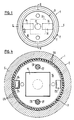
- Figures 1-4 show a double-sided magnetic compass of the simplest type with a mirror-symmetrical structure.
- the magnetic compass 1 consists of the housing 2, the movable part 3 and the pointer arrangement 4 arranged on both sides.
- the housing 2 consists essentially of the annular side part 5 and the two transparent cover parts 6, in which the fixed scale 11 is embedded.
- the annular side part 5 has on its surfaces a groove 7, into each of which an annular rib 8 fits on the cover sides 6, the cover sides being fastened in the side part by means of a suitable adhesive 9.
- the inside 10 of the annular side part is concave and polished in order to ensure that the balls 23 roll on it smoothly.
- the fixed scale 11 is indicated, which works with the two pointers 14 and 15.
- the movable part 3 is constructed from two identical parts in each case and contains a disk-shaped magnet housing 16 which has a conical surface Has elevation 17, the tip of which represents the center of the pointer arrangement and has two rectangular cutouts 18 in which the pointers 14 and 15 are embedded.
- the magnet housing 16 serves to hold a magnet 19, which consists of a rare earth-cobalt alloy, in particular a samarium-cobalt alloy, or is a metallic glass. However, another suitable magnetic substance can also be used, which can either be cuboid or can have any other shape.
- the two pointers 14 and 15 each have a pin 20 which is embedded in a corresponding hole in the magnet housing.
- the end face 21 of the magnet housing is curved outwards and forms an intermediate space 22 with the inner surface 10.
- the curved surface 21 has a bevel 24 such that a V-shaped groove 24 is formed, which forms the other running surface of the spherical ring and holding the bullets.
- the disk-shaped magnet housing consists of two identical parts and furthermore has two recesses 25 for receiving a weight compensation cylinder 26, which can be made of brass, for example, see FIG. 2.
- a weight compensation cylinder 26 which can be made of brass, for example, see FIG. 2.
- FIG. 3 shows a section perpendicular to FIG. 2, two centering pins 27 can be seen, which are fastened in a corresponding bore 28 in the magnet housing.
- Suitable material for the magnet housing and the ring-shaped side part is, above all, a suitable, hard plastic that enables the required smooth running surfaces.
- the transparent cover sides are also conveniently made of plastic.
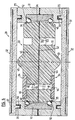
- FIG. 5 shows an embodiment variant for the double-sided magnetic compass, two cuts combined in one figure, analogous to FIGS. 2 and 3 of the first exemplary embodiment.
- the housing 29 of the magnetic compass 30 is also in this Design variant from an annular side part 31, two transparent cover sides 32 and the movable part 33 with the pointer arrangement 34.
- the entire magnetic compass body is also constructed symmetrically and the circumferential ribs 35 in the cover sides are fitted into corresponding grooves 36 in the side part 31 by means of adhesive and attached.
- the fixed scale 37 is also arranged on the transparent cover parts.
- the annular side part is also made in two parts and glued together.
- the movable part 33 is held by two spherical rings 38 and 39, the balls 40 here likewise being made of an amagnetic material.
- the balls are held on the outside by a double cage ring 41, which is embedded in the ring-shaped side part 31, and whose two inwardly facing edges 42 are arcuate in such a way that the balls are freely movable, but are held without play.
- the movable part 33 consists of two identical disc halves 43, on which the pointers 45 and 46 are arranged or let in, wherein these pointers can be inserted into corresponding bores 48 by means of pins 47.
- the disc halves 43 and 44 of this movable part have a conical elevation 49 in their center and are connected to one another via centering pins 50 which are fitted into corresponding bores 51.
- the magnetic substance is not cuboid as in the previous embodiment variant, but as a flat one Magnetic disk 52, which can be produced, for example, by vapor deposition and subsequent alignment.
- This disk has corresponding openings 53 at the location of the centering pins 50.
- Such a magnetic disk can also be used in the first exemplary embodiment according to FIGS. 1 to 4.
- the outer edge 54 of the disc halves is convex and its surface is such that the balls 40 can roll on it effortlessly.
- the movable part presents itself as a relatively flat disc, it is possible to make it spherical, which also makes it possible to align it spatially, for example on the polar star.
- the second embodiment is also relatively easy to manufacture and assemble in order to produce a precise compass that can be read from both sides.
- FIGS. 6 and 7 show a simpler embodiment of a compass, the movable part of which is also mounted on a spherical ring.
- the compass 55 contains a housing 56 made of non-magnetic brass, which is closed at the top with a transparent cover 57. This cover, best vapor-deposited from below as in the other exemplary embodiments, has the fixed scale 12.
- Figure 6 in which the compass is shown in top view, the cover glass with the scale is omitted.
- the housing 56 there is an insert 58 made of plastic, which has a polished, hemispherical running surface 59. This insert is pressed into the housing and glued and sealed with it.
- the movable part 60 consists of an annular part 61 in which the magnet 62 is fitted and a disc 68 thereon on which the Pointers 63 and 64 are arranged.
- the hands can either be embedded or glued on or simply colored in the mass. If necessary, the magnet housing also contains recesses to attach a balance weight.
- the disk has a conical elevation 65 on its surface, which defines the center point. The notch 66 is for alignment purposes.
- the movable part 60 rests on rings 67 arranged in the form of a ring, which on the one hand are made of an amagnetic material and on the other hand together result in a weight which is greater than the rest of the compass body. This ensures that the balls or the moving part are always in the correct position.
- the dimensions of the magnet housing and the conical elevation with respect to the cover glass or the running surface must be dimensioned such that the balls always remain arranged in a ring and a ball cannot escape in any position.
Landscapes
- Engineering & Computer Science (AREA)
- Radar, Positioning & Navigation (AREA)
- Remote Sensing (AREA)
- Physics & Mathematics (AREA)
- General Physics & Mathematics (AREA)
- Lenses (AREA)
- Transmission And Conversion Of Sensor Element Output (AREA)
- Electrochromic Elements, Electrophoresis, Or Variable Reflection Or Absorption Elements (AREA)
- Soft Magnetic Materials (AREA)
- Toys (AREA)
Description
- Die vorliegende Erfindung bezieht sich auf einen Magnetkompass, der ein Gehäuse und ein bewegliches Teil, an dem mindestens eine Zeigeranordnung angebracht ist, aufweist, wobei zwischen dem Gehäuse und dem beweglichen Teil Kugeln angeordnet sind. Ein solcher Magnetkompass, beziehungsweise Magnetkompass-Körper, ist aus der EP-A-181834 bekannt, wobei diese Ausführungsform als eine der vielen möglichen Varianten in Figur 9 aufgeführt ist und der bewegliche Teil, beziehungsweise Lageranordnung, auf einem im Gehäuseboden befestigten Lagerstift aufgehängt ist. Dabei wird in dieser Variante die bewegliche Lageranordnung durch ein Kugelbett geführt.
- Es ist davon ausgehend Aufgabe der vorliegenden Erfindung einen Magnetkompass anzugeben, bei welchem die Notwendigkeit entfällt, einen Lagerstift zu verwenden und der mindestens so präzise ist und einfach herstellbar ist. Diese Aufgabe wird mit einem im Anspruch 1 definierten Magnetkompass gelöst.
- Es ist eine Aufgabe einer Weiterbildung der vorliegenden Erfindung einen Kompass anzugeben, der von beiden Seiten ablesbar ist. Diese Aufgabe wird mit den Merkmalen von Anspruch 2 gelöst.
- Die Erfindung wird im folgenden anhand einer Zeichnung von Ausführungsbeispielen näher erläutert.
- Figur 1 zeigt in Draufsicht ein erstes Ausführungsbeispiel eines von zwei Seiten ablesbaren Magnetkompasses ohne Abdeckgläser,
- Figur 2 zeigt einen Schnitt gemäss der Linie II-II in Figur 1,
- Figur 3 zeigt einen Schnitt gemäss der Linie III-III und
- Figur 4 zeigt einen Schnitt gemäss der Linie IV-IV in Figur 2,
- Figur 5 zeigt eine Ausführungsvariante zum Kompass gemäss Figur 1,
- Figur 6 zeigt als zweites Ausführungsbeipiel einen von einer Seite ablesbaren Kompass, und
- Figur 7 zeigt einen Schnitt gemäss der Linie VII-VII in Figur 6.
- Die Figuren 1 - 4 zeigen einen doppelseitigen Magnetkompass einfachster Bauart mit einem spiegelsymmetrischen Aufbau. In den beiden Schnittfiguren 2 und 3 erkennt man, dass der Magnetkompass 1 aus dem Gehäuse 2, dem beweglichen Teil 3 sowie der beidseitig angeordneten Zeigeranordnung 4 besteht. Das Gehäuse 2 besteht im wesentlichen aus dem ringförmigen Seitenteil 5 sowie den beiden durchsichtigen Deckteilen 6, in denen die feste Skala 11 eingelassen ist. Das ringförmige Seitenteil 5 weist an seinen Oberflächen eine Nut 7 auf, in die je eine ringförmige Rippe 8 an den Deckseiten 6 passt, wobei die Deckseiten mittels einem geeigneten Klebstoff 9 im Seitenteil befestigt sind. Die Innenseite 10 des ringförmigen Seitenteils ist konkav ausgebildet und poliert, um ein störungsfreies Abrollen der Kugeln 23 darauf zu gewährleisten. In Figur 2 ist die feste Skala 11 angedeutet, die mit den beiden Zeigern 14 und 15 zusammenarbeitet.
- Das bewegliche Teil 3 ist aus jeweils zwei identischen Teilen aufgebaut und enthält ein scheibenförmiges Magnetgehäuse 16, das an seiner Oberfläche eine konische Erhebung 17 aufweist, deren Spitze den Mittelpunkt der Zeigeranordnung darstellt und zwei rechteckige Ausschnitte 18 aufweist, in denen die Zeiger 14 und 15 eingelassen sind. Das Magnetgehäuse 16 dient der Aufnahme eines Magneten 19, der aus einer Seltenerden-Kobalt-, insbesondere aus einer Samarium-Kobalt-Legierung besteht, oder ein metallisches Glas ist. Es kann aber auch eine andere, geeignete magnetische Substanz verwendet werden, die entweder quaderförmig sein kann oder irgend eine andere Gestalt aufweisen kann. Die beiden Zeiger 14 und 15 weisen je einen Zapfen 20 auf, der in einer entsprechenden Bohrung im Magnetgehäuse eingelassen ist. Die Stirnseite 21 des Magnetgehäuses ist nach aussen gewölbt und bildet mit der Innenfläche 10 einen Zwischenraum 22. Zur Mitte hin weist die gewölbte Fläche 21 eine Abschrägung 24 auf, derart, dass eine V-förmige Nut 24 entsteht, welche die andere Lauffläche des Kugelkranzes bildet und die Kugeln hält. Wie insbesondere aus den Figuren 2 und 3 hervorgeht, besteht das scheibenförmige Magnetgehäuse aus zwei identischen Teilen und weist ferner zwei Ausnehmungen 25 zur Aufnahme eines Gewichtsausgleichs-Zylinders 26 auf, der beispielsweise aus Messing gearbeitet sein kann, siehe Figur 2. In Figur 3, der einen zu Figur 2 senkrechten Schnitt zeigt, erkennt man zwei Zentrierzapfen 27, die in einer entsprechenden Bohrung 28 im Magnetgehäuse befestigt sind. Als Material für das Magnetgehäuse sowie das ringförmige Seitenteil kommt vor allem ein geeigneter, harter Kunststoff in Frage, der die erforderlichen glatten Laufflächen ermöglicht. Die durchsichtigen Deckseiten werden auch zweckmässigerweise aus Kunststoff gefertigt.
- In Figur 5 ist eine Ausführungsvariante zum doppelseitigen Magnetkompass eingezeichnet, wobei es sich um zwei Schnitte in einer Figur vereint handelt, analog den Figuren 2 und 3 des ersten Ausführungsbeispiels. Das Gehäuse 29 von Magnetkompass 30 besteht auch in dieser Ausführungsvariante aus einem ringförmigen Seitenteil 31, zwei durchsichtigen Deckseiten 32 und dem beweglichen Teil 33 mit der Zeigeranordung 34. Der ganze Magnetkompass-Körper ist ebenfalls symmetrisch aufgebaut und die umlaufenden Rippen 35 in den Deckseiten sind in entsprechende Nuten 36 im Seitenteil 31 mittels Klebstoff eingepasst und befestigt. Auf den durchsichtigen Deckteilen ist ebenfalls die feste Skala 37 angeordnet. In Abweichung vom vorhergehenden Ausführungsbeispiel ist das ringförmige Seitenteil ebenfalls zweiteilig ausgeführt und miteinander verklebt.
- Das bewegliche Teil 33 wird in dieser Ausführungsvariante durch zwei Kugelkränze 38 und 39 gehalten, wobei die Kugeln 40 hier ebenfalls aus einem amagnetischen Material bestehen. Ein derartiges Material ist unter dem Handelsnamen Arkap bekannt und die Kugeln weisen beispielsweise einen Durchmesser von 1 mm auf. Die Kugeln sind aussen von einem Doppelkäfig-Ring 41 gehalten, der im ringförmigen Seitenteil 31 eingelassen ist, und dessen beide nach innen weisenden Kanten 42 bogenförmig ausgebildet sind, derart, dass die Kugeln frei beweglich, jedoch ohne Spiel gehalten sind.
- Das bewegliche Teil 33 besteht aus zwei identischen Scheibenhälften 43, auf denen die Zeiger 45 und 46 angeordnet, beziehungsweise eingelassen sind, wobei diese Zeiger mittels Zapfen 47 in entsprechende Bohrungen 48 gesteckt werden können. Die Scheibenhälften 43 und 44 dieses beweglichen Teils weisen in ihrer Mitte eine konische Erhebung 49 auf und sind über Zentrierzapfen 50 miteinander verbunden, die in entsprechende Bohrungen 51 eingepasst sind.
- In dieser Ausführungsvariante ist die magnetische Substanz nicht quaderförmig ausgebildet wie in der vorhergehenden Ausführungsvariante, sondern als flache Magnetscheibe 52, die beispielsweise durch Aufdampfen und anschliessendes Ausrichten hergestellt werden kann. Diese Scheibe besitzt an der Stelle der Zentrierzapfen 50 entsprechende Durchbrechungen 53. Eine solche Magnetscheibe kann auch beim ersten Ausführungsbeispiel gemäss den Figuren 1 bis 4 Verwendung finden. Die Aussenkante 54 der Scheibenhälften ist konvex ausgebildet und dessen Oberfläche derart beschaffen, dass die Kugeln 40 mühelos darauf abrollen können.
- Während sich in beiden Ausführungsformen das bewegliche Teil als relativ flache Scheibe darstellt, ist es möglich, diesen kugelförmig zu gestalten, wodurch auch eine räumliche Ausrichtung desselben, beispielsweise auf den Polarstern, möglich wird. Auch die zweite Ausführungsvariante ist relativ einfach herstell- und zusammensetzbar, um einen präzisen Kompass zu ergeben, der von beiden Seiten ablesbar ist.
- In den Figuren 6 und 7 ist eine einfachere Ausführungsform eines Kompasses dargestellt, dessen bewegliches Teil ebenfalls auf einem Kugelkranz gelagert ist. Der Kompass 55 enthält ein Gehäuse 56 aus amagnetischem Messing, das oben mit einer durchsichtigen Abdeckung 57 abgeschlossen ist. Diese Abdeckung weist, am besten wie bei den übrigen Ausführungsbeispielen von unten aufgedampft, die feste Skala 12 auf. In Figur 6, in welcher der Kompass in der Aufsicht gezeigt wird, ist das Deckglas mit der Skala weggelassen. Im Gehäuse 56 befindet sich ein Einsatz 58 aus Kunststoff, der eine polierte, halbkugelförmige Lauffläche 59 aufweist. Dieser Einsatz wird in das Gehäuse eingepresst und mit diesem verklebt und abgedichtet.
- Das bewegliche Teil 60 besteht aus einem ringförmigen Teil 61, in welchem der Magnet 62 eingepasst ist und einer daraufliegenden Scheibe 68, auf welcher die Zeiger 63, respektive 64 angeordnet sind. Dabei können die Zeiger entweder eingelassen oder aufgeklebt oder einfach in der Masse gefärbt sein. Falls notwendig, enthält das Magnetgehäuse auch Vertiefungen, um ein Ausgleichgewicht anzubringen. Die Scheibe weist an ihrer Oberfläche eine konische Erhebung 65 auf, die den Mittelpunkt definiert. Die Kerbe 66 dient Ausrichtungszwecken.
- Das bewegliche Teil 60, respektive die Unterseite der überlappenden Scheibe und die Aussenseite des ringförmigen Teils, ruht auf kranzförmig angeordneten Kugeln 67, die einerseits aus einem amagnetischen Material gefertigt sind und andererseits zusammen ein Gewicht ergeben, das grösser als der übrige Teil des Kompasskörpers ist. Damit ist gewährleistet, dass die Kugeln, respektive das bewegliche Teil, stets in der richtigen Lage angeordnet sind. Selbstverständlich müssen dabei die Dimensionen des Magnetgehäuses und der konischen Erhebung in Bezug auf das Deckglas, respektive der Lauffläche derart bemessen sein, dass die Kugeln stets kranzförmig angeordnet bleiben und in keiner Lage eine Kugel entweichen kann.
Claims (14)
- Magnetkompass, der ein Gehäuse (2, 29, 56) und ein bewegliches Teil (3, 33, 60), an dem mindestens eine Zeigeranordnung (4, 34) angebracht ist, aufweist, wobei zwischen dem Gehäuse und dem beweglichen Teil Kugeln (23, 40, 67) angeordnet sind, dadurch gekennzeichnet, dass das bewegliche Teil (3, 33, 60) nur auf mindestens einem Kugelkranz (23; 38; 67) aufliegt, wobei die darin frei beweglichen Kugeln (23, 40, 67) entweder am beweglichen Teil (3, 60) gehalten sind und auf einer mit dem Gehäuse fest verbundenen, konkaven Fläche (10, 59) ablaufen, oder am Gehäuse (29, 56) gehalten sind und auf der konvexen Aussenfläche (54) des beweglichen Teils (33) ablaufen.
- Magnetkompass nach Anspruch 1, dadurch gekennzeichnet, dass die Zeigeranordnung (4; 34) auf beiden Oberflächen des beweglichen Teils (3, 33) angebracht ist.
- Magnetkompass nach Anspruch 1 oder 2, dadurch gekennzeichnet, dass das bewegliche Teil (3) mit den Zeigeranordnungen (4) auf einem Kranz von Kugeln (23) gelagert ist, wobei die Kugeln einerseits an der konkaven Innenfläche (10) des ringförmigen Seitenteils (5) und andererseits an der eine V-förmige Nut (24) enthaltenden, konvexen Seite (21) des Magnetgehäuses (16) des scheibenförmigen, beweglichen Teils ablaufen.
- Magnetkompass nach Anspruch 1 oder 2, dadurch gekennzeichnet, dass das bewegliche Teil (33) mit den Zeigeranordnungen (34) auf zwei Kugel-Kränzen (38, 39) gelagert ist, wobei die Kugeln (40) einerseits an einem Doppelkäfigring (41) mit zwei konkaven Ecken (42) und andererseits an der konvex geformten Seite (54) des scheibenförmigen beweglichen Teils ablaufen.
- Magnetkompass nach Anspruch 3 oder 4, dadurch gekennzeichnet, dass das Gehäuse (2, 39) zwei aus einem durchsichtigen Material gefertigte Deckscheiben (6, 32) mit eingelegter fester Skala (11, 37) aufweist, die je mittels einer Rippe (8, 35) in einer entsprechenden Nut (7, 36) im ringförmigen Seitenteil (5, 31) befestigt sind.
- Magnetkompass nach einem der Ansprüche 2 bis 5, dadurch gekennzeichnet, dass sowohl das Gehäuse als auch das bewegliche Teil spiegelsymmetrisch ausgebildete und angeordnete Teile aufweist.
- Magnetkompass nach einem der Ansprüche 1 bis 6, dadurch gekennzeichnet, dass die Magnetsubstanz (19) quaderförmig ausgebildet und im Magnetgehäuse (16; 43, 44) angeordnet ist.
- Magnetkompass nach einem der Ansprüche 1 bis 6, dadurch gekennzeichnet, dass die Magnetsubstanz (52) als aufgedampfte und gerichtete Scheibe zwischen den beiden Magnetgehäuse-Hälften angeordnet ist.
- Magnetkompass nach Anspruch 1 mit einer Zeigeranordnung, dadurch gekennzeichnet, dass das Gehäuse (56) aus einem amagnetischen Material gefertigt ist und einen Kunststoff-Einsatz (58) enthält, der eine halbkugelförmige Lauffläche (59) aufweist, auf der der Kugelkranz (67), auf dem das bewegliche Teil (60) ruht, abläuft.
- Magnetkompass nach Anspruch 9, dadurch gekennzeichnet, dass das bewegliche Teil (60) im wesentlichen aus einem ringförmigen Teil (61) mit aufgesetzter Scheibe (68) grösseren Durchmessers besteht, wobei die Aussenseite des ringförmigen Teils sowie die Unterseite des hervorstehenden Scheibenteils die andere Lauffläche der Kugeln (67) ergeben und das Innere des ringförmigen Teils die Magnetsubstanz aufnimmt, und die Scheibenoberseite die Zeigeranordnung (63, 64) trägt.
- Magnetkompass nach Anspruch 9 oder 10, dadurch gekennzeichnet, dass das Gewicht der Kugeln (67) insgesamt grösser ist als das Gewicht der übrigen Teile des Kompasses.
- Magnetkompass nach einem der Ansprüche 1 bis 11, dadurch gekennzeichnet, dass die Zeigeranordnung nebst den beiden Zeigern und Skalenteilen in ihrer Mitte eine konische Erhebung (17, 65) enthält.
- Magnetkompass nach einem der Ansprüche 1 bis 12, dadurch gekennzeichnet, dass das bewegliche Teil ausgebildet ist, Gewichtsausgleichszylinder (26) aufzunehmen.
- Magnetkompass nach einem der Ansprüche 1 bis 13, dadurch gekennzeichnet, dass die Kugeln aus einem amagnetischen Metall gefertigt sind und einen Durchmesser von 1 mm aufweisen.
Priority Applications (3)
| Application Number | Priority Date | Filing Date | Title |
|---|---|---|---|
| DE59006850T DE59006850D1 (de) | 1990-11-21 | 1990-11-21 | Magnetkompass. |
| EP90810899A EP0486742B1 (de) | 1990-11-21 | 1990-11-21 | Magnetkompass |
| AT90810899T ATE110164T1 (de) | 1990-11-21 | 1990-11-21 | Magnetkompass. |
Applications Claiming Priority (1)
| Application Number | Priority Date | Filing Date | Title |
|---|---|---|---|
| EP90810899A EP0486742B1 (de) | 1990-11-21 | 1990-11-21 | Magnetkompass |
Publications (2)
| Publication Number | Publication Date |
|---|---|
| EP0486742A1 EP0486742A1 (de) | 1992-05-27 |
| EP0486742B1 true EP0486742B1 (de) | 1994-08-17 |
Family
ID=8205968
Family Applications (1)
| Application Number | Title | Priority Date | Filing Date |
|---|---|---|---|
| EP90810899A Expired - Lifetime EP0486742B1 (de) | 1990-11-21 | 1990-11-21 | Magnetkompass |
Country Status (3)
| Country | Link |
|---|---|
| EP (1) | EP0486742B1 (de) |
| AT (1) | ATE110164T1 (de) |
| DE (1) | DE59006850D1 (de) |
Families Citing this family (1)
| Publication number | Priority date | Publication date | Assignee | Title |
|---|---|---|---|---|
| CN104197905B (zh) * | 2014-09-15 | 2016-05-11 | 瑞安市顺风航仪有限公司 | 一种防气泡回流上室的磁罗经 |
Family Cites Families (2)
| Publication number | Priority date | Publication date | Assignee | Title |
|---|---|---|---|---|
| DE2028114A1 (de) * | 1970-06-08 | 1971-12-16 | Bartlett Compass Co Ltd | Magnetkompass |
| EP0181834B1 (de) * | 1984-10-29 | 1991-12-18 | Patrick Stolz | Magnetkompass-Körper |
-
1990
- 1990-11-21 EP EP90810899A patent/EP0486742B1/de not_active Expired - Lifetime
- 1990-11-21 DE DE59006850T patent/DE59006850D1/de not_active Expired - Fee Related
- 1990-11-21 AT AT90810899T patent/ATE110164T1/de not_active IP Right Cessation
Also Published As
| Publication number | Publication date |
|---|---|
| DE59006850D1 (de) | 1994-09-22 |
| ATE110164T1 (de) | 1994-09-15 |
| EP0486742A1 (de) | 1992-05-27 |
Similar Documents
| Publication | Publication Date | Title |
|---|---|---|
| DE3047606A1 (de) | "lagerung" | |
| EP0396946B1 (de) | Lupenanordnung | |
| EP0486742B1 (de) | Magnetkompass | |
| DE4025829A1 (de) | Halterung fuer den taster von koordinatenmessmaschinen | |
| WO2007012939A1 (de) | Gehäuse zur abschirmung magnetischer felder | |
| EP0756722B1 (de) | Uhrengehäuse | |
| EP0369096A2 (de) | Armbanduhr | |
| DE359903C (de) | Magnetische Daempfvorrichtung fuer schwingende Systeme, insbesondere fuer Messinstrumente | |
| DE3246252A1 (de) | Messtaster | |
| CH322328A (de) | Uhrengehäuse | |
| DE8234894U1 (de) | Kompassgeraet | |
| AT223695B (de) | Stoßgesichertes Lager für Präzisionsapparate, Meßinstrumente u. dgl. | |
| DE872126C (de) | Wirbelstromdrehzahlmesser | |
| DE1236838B (de) | Planetarium in Gestalt eines Hohlkoerpers mit Himmelskoerperdarstellungen an dessen Innenwand | |
| DE725328C (de) | Rohrgelenk fuer eine Eisenbahn-Heizdampfkupplung | |
| DE850691C (de) | Anschlusskupplung einer Luftleitung an den Scheibenzwischenraum des Fensters einer Flugzeugkabine | |
| DE69508146T2 (de) | Vorrichtung mit Kreisförmiger Platte und einer Zahl von an dem Umfang dieser Platte liegenden Fächern und Spiel mit so einer Vorrichtung | |
| DE959698C (de) | Axiale Lagerung einer Revolverhuelse auf einem Zapfen | |
| WO2005012776A1 (de) | Kugelventil | |
| DE1220224B (de) | Magnetisch, praktisch reibungslos gelagerte, bezueglich Drehung um ihre Laengsachsein indifferentem Gleichgewicht befindliche, horizontale oder annaehernd horizontale Systemachse | |
| DE959062C (de) | Magnetsystem mit Schneidenlagerung, insbesondere fuer magnetische Feldwaagen | |
| DE102018208408A1 (de) | Vorrichtung zum Spielen | |
| AT200824B (de) | Stereophonische Schallauffangeinrichtung | |
| AT223028B (de) | Aus zwei gekreuzten Prismen bestehender Indikator für Spiegelreflexkameras | |
| DE1400643U (de) |
Legal Events
| Date | Code | Title | Description |
|---|---|---|---|
| PUAI | Public reference made under article 153(3) epc to a published international application that has entered the european phase |
Free format text: ORIGINAL CODE: 0009012 |
|
| AK | Designated contracting states |
Kind code of ref document: A1 Designated state(s): AT BE CH DE DK ES FR GB GR IT LI LU NL SE |
|
| RBV | Designated contracting states (corrected) |
Designated state(s): AT CH DE FR GB IT LI SE |
|
| 17P | Request for examination filed |
Effective date: 19921125 |
|
| 17Q | First examination report despatched |
Effective date: 19930817 |
|
| GRAA | (expected) grant |
Free format text: ORIGINAL CODE: 0009210 |
|
| ITF | It: translation for a ep patent filed | ||
| AK | Designated contracting states |
Kind code of ref document: B1 Designated state(s): AT CH DE FR GB IT LI SE |
|
| REF | Corresponds to: |
Ref document number: 110164 Country of ref document: AT Date of ref document: 19940915 Kind code of ref document: T |
|
| GBT | Gb: translation of ep patent filed (gb section 77(6)(a)/1977) |
Effective date: 19940817 |
|
| REF | Corresponds to: |
Ref document number: 59006850 Country of ref document: DE Date of ref document: 19940922 |
|
| PGFP | Annual fee paid to national office [announced via postgrant information from national office to epo] |
Ref country code: SE Payment date: 19941027 Year of fee payment: 5 |
|
| PGFP | Annual fee paid to national office [announced via postgrant information from national office to epo] |
Ref country code: AT Payment date: 19941130 Year of fee payment: 5 |
|
| ET | Fr: translation filed | ||
| EAL | Se: european patent in force in sweden |
Ref document number: 90810899.6 |
|
| PLBE | No opposition filed within time limit |
Free format text: ORIGINAL CODE: 0009261 |
|
| STAA | Information on the status of an ep patent application or granted ep patent |
Free format text: STATUS: NO OPPOSITION FILED WITHIN TIME LIMIT |
|
| 26N | No opposition filed | ||
| PG25 | Lapsed in a contracting state [announced via postgrant information from national office to epo] |
Ref country code: AT Effective date: 19951121 |
|
| PG25 | Lapsed in a contracting state [announced via postgrant information from national office to epo] |
Ref country code: SE Effective date: 19951122 |
|
| EUG | Se: european patent has lapsed |
Ref document number: 90810899.6 |
|
| PGFP | Annual fee paid to national office [announced via postgrant information from national office to epo] |
Ref country code: GB Payment date: 19961015 Year of fee payment: 7 |
|
| PGFP | Annual fee paid to national office [announced via postgrant information from national office to epo] |
Ref country code: FR Payment date: 19961025 Year of fee payment: 7 |
|
| PG25 | Lapsed in a contracting state [announced via postgrant information from national office to epo] |
Ref country code: GB Free format text: LAPSE BECAUSE OF NON-PAYMENT OF DUE FEES Effective date: 19971121 |
|
| PG25 | Lapsed in a contracting state [announced via postgrant information from national office to epo] |
Ref country code: FR Free format text: THE PATENT HAS BEEN ANNULLED BY A DECISION OF A NATIONAL AUTHORITY Effective date: 19971130 |
|
| GBPC | Gb: european patent ceased through non-payment of renewal fee |
Effective date: 19971121 |
|
| REG | Reference to a national code |
Ref country code: FR Ref legal event code: ST |
|
| PGFP | Annual fee paid to national office [announced via postgrant information from national office to epo] |
Ref country code: DE Payment date: 20001221 Year of fee payment: 11 |
|
| PG25 | Lapsed in a contracting state [announced via postgrant information from national office to epo] |
Ref country code: DE Free format text: LAPSE BECAUSE OF NON-PAYMENT OF DUE FEES Effective date: 20020702 |
|
| PGFP | Annual fee paid to national office [announced via postgrant information from national office to epo] |
Ref country code: CH Payment date: 20031124 Year of fee payment: 14 |
|
| PG25 | Lapsed in a contracting state [announced via postgrant information from national office to epo] |
Ref country code: LI Free format text: LAPSE BECAUSE OF NON-PAYMENT OF DUE FEES Effective date: 20041130 Ref country code: CH Free format text: LAPSE BECAUSE OF NON-PAYMENT OF DUE FEES Effective date: 20041130 |
|
| REG | Reference to a national code |
Ref country code: CH Ref legal event code: PL |
|
| PG25 | Lapsed in a contracting state [announced via postgrant information from national office to epo] |
Ref country code: IT Free format text: LAPSE BECAUSE OF NON-PAYMENT OF DUE FEES;WARNING: LAPSES OF ITALIAN PATENTS WITH EFFECTIVE DATE BEFORE 2007 MAY HAVE OCCURRED AT ANY TIME BEFORE 2007. THE CORRECT EFFECTIVE DATE MAY BE DIFFERENT FROM THE ONE RECORDED. Effective date: 20051121 |