EP0483753A2 - Röntgen-Spektralphotometer - Google Patents
Röntgen-Spektralphotometer Download PDFInfo
- Publication number
- EP0483753A2 EP0483753A2 EP91118412A EP91118412A EP0483753A2 EP 0483753 A2 EP0483753 A2 EP 0483753A2 EP 91118412 A EP91118412 A EP 91118412A EP 91118412 A EP91118412 A EP 91118412A EP 0483753 A2 EP0483753 A2 EP 0483753A2
- Authority
- EP
- European Patent Office
- Prior art keywords
- pulse
- height
- window
- subordinate
- selector
- Prior art date
- Legal status (The legal status is an assumption and is not a legal conclusion. Google has not performed a legal analysis and makes no representation as to the accuracy of the status listed.)
- Granted
Links
Images

Classifications
-
- G—PHYSICS
- G01—MEASURING; TESTING
- G01T—MEASUREMENT OF NUCLEAR OR X-RADIATION
- G01T1/00—Measuring X-radiation, gamma radiation, corpuscular radiation, or cosmic radiation
- G01T1/36—Measuring spectral distribution of X-rays or of nuclear radiation spectrometry
Definitions
- This invention relates to wavelength-dispersive X-ray spectrometer used in combination with a proportional counter tube.
- Electromagnetic analysis is used to extract chemical information indicative of a substance through phenomena such as light emission, absorption, reflection, fluorescence, phosphorescence, scattering, diffraction and optical rotation, which occur as the result of an interaction between electromagnetic waves and the substance.
- Examples of electromagnetic analysis in which the wavelength region of the electromagnetic waves of interest is the X-ray region include fluorescent X-ray analysis (XRF) using X-rays as the source of excitation, EPMA using an electron beam narrowed down to less than one micrometer, and PIXE using a charged-particle beam such as a proton or helium-ion beam.
- XRF fluorescent X-ray analysis
- EPMA electron beam narrowed down to less than one micrometer
- PIXE a charged-particle beam such as a proton or helium-ion beam.
- Characteristic X-rays which are specific to an element, are emitted from a specimen excited by irradiation, and the X-rays are separated into spectral components by an analyzing crystal and then detected by a detector.
- a counting mechanism for counting the characteristic X-rays detected usually is provided with an amplifier for amplifying output pulses from the detector, a pulse-height selector (also referred to as a pulse-height analyzer) for selecting those amplified output pulses which have peak values within a specific range, and a counter for counting the output pulses selected by the pulse-height selector.
- a gas-filled detector such as a proportional counter tube is used as the detector and operates when a high-voltage is applied thereto.
- a detector of this kind an increase in the strength of the entrant X-rays enlarges the amount of space charge within the detector so that there is a decrease in the effective detector voltage. This brings about a phenomenon referred to as an energy shift, in which there is a decrease in the peak value of the detector output pulse.
- the output pulses not selected by the pulse-height selector increase in number even if they are output pulses of the characteristic X-rays indicative of the element of interest, and hence there is an increase in the number of pulses which fail to be counted.
- the simplest methods of applying this correction according to the prior art include a method which involves taking the energy shift into consideration and, if there is a shift in the pulse-height distribution, setting the window of the pulse-height selector to be large enough so that the entire distribution will fall within this window.
- Another simple method used when the range of intensities of measured X-rays is unspecified involves investigating the relationship between X-ray intensity and energy shift by actual measurement to obtain a correction function in advance, and automatically controlling the gain of the measurement system by this correction function when a specimen is measured. According to these methods, the window of the pulse-height selector is set to be large.
- a disadvantage which results is a corresponding increase in noise and a decline in measurement sensitivity.
- the conventional fluorescent X-ray spectrometer includes one in which the output end of the pulse-height selector is separately provided with a counting rate meter, and a high-voltage generator is controlled by the output signal from the counting rate meter in such a manner that the high voltage applied to the detector is corrected in conformity with X-ray intensity.
- the counting rate meter for controlling the high voltage of the detector is provided for output pulses which have passed through the pulse-height selector. As a consequence, all of the output pulses from the detector are not counted; only the output pulses of a target energy are counted.
- the energy shift of a detector is dependent upon the strength of all X-rays that impinge upon the detector and is decided by the ionization count of the gas within the detector. Accordingly, though the high-voltage correction of the detector is applied with regard to X-rays of the target energy in the conventional fluorescent X-ray spectrometer, no correction is applied for X-rays of a non-essential energy. Consequently, in a case where there are many non-essential X-rays, a problem which arises is that the high-voltage correction of the detector is rendered inadequate and an improvement in analytical precision cannot be achieved.
- a probe for fluorescent X-ray measurement having means for varying the magnitude of the high voltage supplied to the detector and adjusting the energy output of the detector to thereby maintain the stability of the apparatus has been disclosed in the specification of Japanese Patent Publication No. 52-21392.
- the output end of an amplifier is provided anew with a high-level discriminator separate from a pulse-height selector in order to correct the high voltage of the detector with regard to all output pulses from the detector, and the high voltage applied to the detector is corrected by the output signal from the high-level discriminator.
- the apparatus has a more complicated mechanism and circuitry and the cost thereof is raised.
- a problem which remains unsolved is that the effects of the high-voltage correction due to higher order diffraction lines cannot be corrected for by the level discriminator.
- Japanese Patent Application No. 59-191256 Japanese Patent Application Laid-Open No. 61-68579
- This apparatus possesses two counting modes, namely a regular count for analytical counting and a preliminary count for correcting the applied voltage of the detector prior to the regular count.
- the upper-limit level of the pulse-height selector is raised and its lower-limit level is lowered by means for setting the level of the pulse-height selector, all output pulses are counted, and the high-voltage applied to the detector is corrected by the set voltage value of high-voltage setting means stored in memory means as a memorized value extracted based upon the value of the count.
- the upper- and lower-limit levels of the pulse-height selector are returned to the normal levels for analytical counting and the high voltage corrected by the preliminary count is applied to the detector so that the latter may carry out X-ray detection.
- this method can be said to be an improvement on the above-described method of investigating the relationship between X-ray intensity and energy shift by actual measurement to obtain a correction function in advance, and automatically controlling the gain of the measurement system by this correction function when a specimen is measured, time is required in order to perform the preliminary count prior to the regular count, and another drawback is that real-time control cannot be carried out.
- a first object of the present invention is to narrowly set the width of the window of a pulse-height selector, which selects the pulse height of output pulses from a proportional counter tube in an X-ray spectrometer, in conformity with the X-ray wavelength to be measured, and detect in real-time an energy shift in a measurement output when a specimen is measured, thereby making it possible to correct the measurement output.
- a second object of the present invention is to reduce the number of output pulses not selected by a pulse-height selector owing to an energy shift in a measurement output of an X-ray spectrometer, thereby eliminating situations in which output pulses go uncounted and establishing a linear relationship between X-ray intensity and pulse counting rate so that the accuracy of analysis is improved.
- a third object of the present invention is to compensate for a fluctuation in a high-voltage power supply and a fluctuation caused by the passage of time and a variation in temperature in an X-ray spectrometer.
- a fourth object of the present invention is to perform an effective correction of the high voltage of a detector in an X-ray spectrometer even when there are many non-essential X-rays, thereby making possible an improvement in analytical accuracy.
- a fifth object of the present invention is to construct an X-ray spectrometer of simple mechanisms and circuitry. These objects are achieved by an X-ray spectrometer according to claim 1 resp. to claim 12. Preferred embodiments are subjects of the dependent claims.
- An X-ray spectrometer has a main pulse-height selector for selecting the pulse height of output pulses from a proportional counter tube, and a subordinate pulse-height selector whose selective window width is within the window width of the main pulse-height selector.
- a shift in the pulse-height distribution of the output pulses from the proportional counter tube is determined from the counting rate of the subordinate pulse-height detector, the energy shift of the proportional counter tube is detected from the shift in the pulse-height distribution, and a driving power supply of the proportional counter tube is controlled so as to eliminate the shift in the pulse-height distribution of the output pulses from the proportional counter tube, thereby compensating for the effects of the energy shift.
- the subordinate pulse-height selector in the X-ray spectrometer of the present invention comprises a plurality of pulse-height selectors whose selective window widths are pulse-height widths at least at the upper and lower ends of each of pulse-height widths obtained by dividing the window width, which has been set for the main pulse-height selector, into n equal portions.
- the difference or ratio between detection values obtained from the plurality of subordinate pulse-height selectors is determined to obtain a feedback signal, and the driving source of the proportional counter tube is driven by this feedback signal.
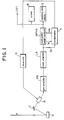
- Fig. 1 is a block diagram showing the overall construction of a wavelength-dispersive X-ray spectrometer in combination with a proportional counter tube.
- an electron beam is illustrated as an example of an irradiating electromagnetic wave.
- the characteristic X-rays which are indicative of various elements, emitted from the specimen S are separated into spectral components by an analyzing crystal C, and the characteristic X-rays of an element to be detected are selected.
- the characteristic X-rays separated into spectral components by the analyzing crystal C are converted into an electrical signal by an X-ray detector D.
- the output signal from a proportional counter tube is a pulsed signal, which is sent to a preamplifier PA.
- the output signal from the preamplifier PA is delivered at a low output impedance to a linear amplifier LA, which sends a pulsed signal proportional to the input signal to a main pulse-height analyzer MPHA, which is the next stage.
- a clipping circuit and a pulse forming circuit are inserted in the linear amplifier LA to uniformalize the shape of the pulses in order to prevent pulse pile-up, which is due to arrival of a succeeding pulse before the preceding pulse is sufficiently attenuated, as well as amplifier overload caused by pulse pile-up.
- the main pulse-height analyzer effects separation into background, such as higher order diffraction lines of characteristic X-rays and higher order diffraction lines of primary X-rays from the specimen, which are detected at the same angle in the analyzing crystal, and a characteristic X-ray spectrum of the element undergoing detection.
- the output signal from the main pulse-height analyzer MPHA is sent to a counter Q, which counts the pulses one at a time and displays the count, or to a counting rate meter, which displays an average count per second.
- the display is presented by a display device such as a CRT.
- a compensator K is a principal constituent of the present invention.
- Information indicating the size of a window set in the main pulse-height analyzer MPHA is inputted to the compensator K, to which the pulsed output signal of the linear amplifier LA is applied.
- the compensator K is adapted to detect the energy shift of the output pulses from the proportional counter tube D, send this detection signal to a drive unit G of the proportional counter tube so as to control the voltage applied to the proportional counter tube D, and perform feedback in such a manner that the energy shift returns to zero.
- Fig. 4 The state of energy shift will be described with reference to Fig. 4, in which the horizontal axis indicates the pulse height of output pulses from the proportional counter tube when X-rays of a certain fixed wavelength impinge thereon, and the vertical axis indicates the counting rate, namely the frequency of occurrence, of each pulse height.
- the window of the main pulse-height analyzer MPHA is set at W0.
- the curve indicated by the solid line is a pulse-height distribution curve which prevails when incident X-ray intensity has a low value
- the curve indicated by the dashed line is a pulse-height distribution curve which prevails when incident X-ray intensity has a high value.
- a plurality of subordinate pulse-height analyzers SPHA are provided in addition to the main pulse-height analyzer MPHA, the windows of these subordinate pulse-height analyzers are set at W1, W2, W3, which are obtained by dividing W0 by three, as shown in Fig. 4, and the output pulses from the proportional counter tube D are applied to the main and subordinate pulse-height analyzers simultaneously.
- the counting rate of the pulses which have passed through the window W2 are maximum and the counting rates of the pulses which have passed through the windows W1, W3 are approximately equal to each other and small.
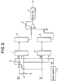
- the compensator K will be described in detail with reference to Fig. 2.
- the compensator K has two subordinate pulse-height analyzers SPHA 1, 2.
- a lower limit V1 of the window of the main pulse-height analyzer MPHA and the value of window width V W are inputted to the subordinate pulse-height analyzers SPHA 1, 2 from the main pulse-height analyzer MPHA.
- the lower limit V1 of the window and the value of window width V W are added by an adding circuit 3 to set an upper-limit level V U of the subordinate pulse-height analyzer SPHA 1, and the window width V W is potentially divided by n in a potentiometer 4 to obtain V W /n.
- the window width of the subordinate pulse-height analyzer SPHA 1 is set by V W /n thus obtained.
- the subordinate pulse-height analyzer SPHA 2 its lower-limit level V l is set by the lower limit V l of the window, and its window width is set by V W /n, which is obtained by potentially dividing V W by n in the potentiometer 4.
- the output pulse signal of the linear amplifier LA which is the same as that inputted to the main pulse-height analyzer MPHA, is applied to the two subordinate pulse-height analyzers SPHA 1, 2. Pulses which have passed through the window corresponding to W3 in Fig. 4 are inputted to a frequency/voltage converter 5 from the subordinate pulse-height analyzer SPHA 1. Similarly, output pulses from the subordinate pulse-height analyzer SPHA 2 are inputted to a frequency/voltage converter 6.
- the frequency/voltage converters 5, 6 output voltages proportional to the counting rates of the respective input pulses.
- the pulse-height distribution of the output pulses from the proportional counter tube D falls, with left-right symmetry, in the center of the window set for the main pulse-height analyzer MPHA. If there is an energy shift, the above-mentioned difference possesses a positive or negative value.
- Numeral 7 in Fig. 2 denotes a subtracting circuit for calculating the difference between the outputs of the frequency/voltage converters 5, 6.
- the output of the subtracting circuit 7 is delivered to the drive unit G of the proportional counter tube D, and feedback is performed in such a manner that the above-mentioned difference becomes zero.
- the setting of the upper-limit level V U , lower-limit level V l and window widths of the subordinate pulse-height analyzers SPHA 1, 2 is performed based upon the lower limit V l and the value of the window width V W of the main pulse-height analyzer MPHA, which are inputted from the main pulse-height analyzer.
- this setting can be made based upon other values as well.
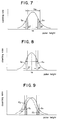
- Other methods of setting the upper-limit level V U , lower-limit level V l and window widths of the subordinate pulse-height analyzers SPHA 1, 2 will be described with reference to Figs. 5 through 8.
- the lower limit V l of the window of the main pulse-height analyzer MPHA and the value of its window width V W are inputted from the main pulse-height analyzer MPHA, and the sum of the lower limit V l of the window and the value of the window width V W is calculated, thereby setting the upper-limit level V U of the subordinate pulse-height analyzer SPHA 1.
- the lower-limit level V l of the subordinate pulse-height analyzer SPHA 2 is set based upon lower limit V l of the window.
- the window widths of the subordinate pulse-height analyzers SPHA are set by inputting a separate ⁇ V.
- the outputs of the frequency/voltage converters 5, 6 which have passed through the windows of the subordinate pulse-height analyzers SPHA 1, 2 in this case are the portions represented by S U , S l , respectively.
- the upper limit V U and the lower limit value V l of the window of the main pulse-height analyzer MPHA are inputted from this analyzer, the upper-limit level V U and lower-limit level V l of the subordinate pulse-height analyzers SPHA 1, 2 are set, and the window widths of the subordinate pulse-height analyzers SPHA are set by inputting a separate ⁇ V.
- the outputs of the frequency/voltage converters 5, 6 which have passed through the windows of the subordinate pulse-height analyzers SPHA 1, 2 in this case are the portions represented by S U , S l , respectively.
- the average value V0 and the value of the window width V W of the main pulse-height analyzer MPHA are inputted from this analyzer, and 1/2 of the window width V W is added to the average value V0, thereby setting the upper-limit level V U of the subordinate pulse-height analyzer SPHA 1.
- 1/2 of the window width V W is subtracted from the average value V0, thereby setting the lower-limit level V l of the subordinate pulse-height analyzer SPHA 2.
- the window widths of the subordinate pulse-height analyzers SPHA are set by inputting a separate ⁇ V.
- the outputs of the frequency/voltage converters 5, 6 which have passed through the windows of the subordinate pulse-height analyzers SPHA 1, 2 in this case are the portions represented by S U , S l , respectively.
- the average value V0 of the main pulse-height analyzer MPHA is inputted from this analyzer, and half of the half-value width is added to the average value V0, thereby setting the upper-limit level V U of the subordinate pulse-height analyzer SPHA 1 and the lower-limit level V l of the subordinate pulse-height analyzer SPHA 2.
- the window widths of the subordinate pulse-height analyzers SPHA are set by inputting a separate ⁇ V.
- the outputs of the frequency/voltage converters 5, 6 which have passed through the windows of the subordinate pulse-height analyzers SPHA 1, 2 in this case are the portions represented by S U , S l , respectively.
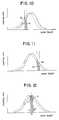
- Fig. 9 is a diagram showing the state of feedback of the pulse-height distribution of the main pulse-height analyzer MPHA. This is the result of the operation of the compensator K.
- the solid line indicates the normal pulse-height distribution.
- the dashed line indicates that the pulse-height distribution is offset to the left, namely toward the side of lower pulse height, owing to an energy shift.
- the two straight lines on the left side form the window of the subordinate pulse-height analyzer SPHA 2
- the two straight lines on the right side form the window of the subordinate pulse-height analyzer SPHA 1.
- the area of the pulse-height distribution represented by the dashed line selected by the window of the subordinate pulse-height analyzer SPHA 2 is S l '
- the area of the pulse-height distribution represented by the dashed line selected by the window of the subordinate pulse-height analyzer SPHA 1 is S U '.
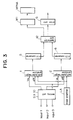
- Fig. 3 is a circuit diagram illustrating another embodiment of the compensator according to the present invention.
- the compensator according to the invention shown in Fig. 3 has at least two subordinate pulse-height analyzers SPHA 1, 2, to which the proportional counter tube D is inputted via the linear amplifier LA.
- the subordinate pulse-height analyzers SPHA 1, 2 have their windows set via a setting unit SU 10.
- the outputs of the subordinate pulse-height analyzers SPHA 1, 2 are converted into voltage signals by the frequency/voltage converters 5, 6, respectively, the voltage signals are processed by an operation unit 12, and the output of the operation unit 12 is fed back to the drive unit G of the proportional counter tube.
- the setting of the windows of the subordinate pulse-height analyzers SPHA 1, 2 by the setting unit SU 10 is performed in the manner shown in Figs. 2, 5, 6, 7 and 8 based upon inputs 1, 2 and 3.
- the mode of signal processing executed by the operation unit 12 is for finding the difference between the outputs of the subordinate pulse-height analyzers SPHA 1, 2, as illustrated in the embodiment of Fig. 2.
- Another mode of signal processing executed by the operation unit 12 is for finding the ratio between the outputs of the subordinate pulse-height analyzers SPHA 1, 2.
- Feedback is applied to the drive unit G of the proportional counter tube in such a manner that the ratio between the outputs becomes one.
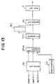
- the aforesaid processing employs two subordinate pulse-height analyzers, it is possible to perform the processing by using one subordinate pulse-height analyzer and make a comparison with a preset value. This embodiment is illustrated in Figs. 10, 11, 12 and 13.
- the embodiment shown in Fig. 13 employs one subordinate pulse-height analyzer, and a memory M2 is provided between a frequency/voltage converter F/V and an operation unit OU.
- This embodiment is practiced by comparing the output obtained via the window set for the single subordinate pulse-height analyzer SPHA with a set value preset in a window the same as that of the subordinate pulse-height analyzer SPHA or with a set value measured via the subordinate pulse-height analyzer SPHA.
- Fig. 10 is for a case where only the subordinate pulse-height analyzer SPHA 2 of Fig. 3 is provided.
- the area S l of the pulse-height distribution represented by the solid line selected by the window of the subordinate pulse-height analyzer SPHA is set in advance or is measured in advance and then stored in the memory M2.
- the area S l ' of the pulse-height distribution represented by the dashed line selected by the window of the subordinate pulse-height analyzer SPHA is compared, by means of the operation unit OU, with the value that has been stored in the memory M2, and feedback is applied to the drive unit G of the proportional counter tube in the same manner as described above.
- Fig. 11 is for a case where only the subordinate pulse-height analyzer SPHA 1 of Fig. 3 is provided.
- the area S U of the pulse-height distribution represented by the solid line selected by the window of the subordinate pulse-height analyzer SPHA is set in advance or is measured in advance and then stored in the memory M2.
- the area S U ' of the pulse-height distribution represented by the dashed line selected by the window of the subordinate pulse-height analyzer SPHA is compared, by means of the operation unit OU, with the value that has been stored in the memory M2, and feedback is applied to the drive unit G of the proportional counter tube in the same manner as described above.
- Fig. 12 is for a case where the window of the subordinate pulse-height analyzer SPHA is set in the vicinity of the average value of the pulse-height distribution represented by the solid line.
- the area S of the pulse-height distribution represented by the solid line selected by the window of the subordinate pulse-height analyzer SPHA is set in advance or is measured in advance and then stored in the memory M2.
- the area S U ' of the pulse-height distribution represented by the dashed line selected by the window of the subordinate pulse-height analyzer SPHA is compared, by means of the operation unit OU, with the value that has been stored in the memory M2, and feedback is applied to the drive unit G of the proportional counter tube in the same manner as described above.
- Fig. 12 it is also possible to apply feedback to the drive unit G of the proportional counter tube in such a manner that the operation unit OU takes the maximum value of the area S of the pulse-height distribution represented by the solid line selected by the window of the subordinate pulse-height analyzer SPHA.
- the memory M2 can be deleted in such case.
- the mode of execution is such that the pulse-height distribution of the signal pulses from the proportional counter tube is a normal distribution (Gaussian distribution) decided by an average and standard deviation. If this distribution according to the invention is adopted, it is considered that an evaluation can be made based upon an average.
- the example of the aforementioned mode of executions is such that the voltage of the drive unit G of the proportional counter tube is controlled by feedback to return the X-ray detection pulse-height distribution per se to the standard position.
- a table is previously prepared which gives the relationship between the ratio of the counting rates of subordinate pulse-height analyzers SPHA 1, 2, namely the ratio of the outputs of the frequency/voltage converters 5, 6 (by performing a logarithmic conversion and obtaining the difference between the results), and correction coefficients by which the counting rate of the output pulses from the main pulse-height analyzer MPHA is to be multiplied.
- the table is stored beforehand in memory 1 and a compensation is made with regard to the counting rate of the output pulses from the main pulse-height analyzer MPHA. This method is useful in a case where the entirety of the X-ray spectrometer is controlled by a computer and data processing also is executed by the same computer.
Landscapes
- Physics & Mathematics (AREA)
- Spectroscopy & Molecular Physics (AREA)
- Health & Medical Sciences (AREA)
- Life Sciences & Earth Sciences (AREA)
- General Physics & Mathematics (AREA)
- High Energy & Nuclear Physics (AREA)
- Molecular Biology (AREA)
- Measurement Of Radiation (AREA)
- Analysing Materials By The Use Of Radiation (AREA)
Applications Claiming Priority (2)
| Application Number | Priority Date | Filing Date | Title |
|---|---|---|---|
| JP02293031A JP3094437B2 (ja) | 1990-10-30 | 1990-10-30 | X線分光装置 |
| JP293031/90 | 1990-10-30 |
Publications (3)
| Publication Number | Publication Date |
|---|---|
| EP0483753A2 true EP0483753A2 (de) | 1992-05-06 |
| EP0483753A3 EP0483753A3 (en) | 1993-02-24 |
| EP0483753B1 EP0483753B1 (de) | 1996-02-28 |
Family
ID=17789597
Family Applications (1)
| Application Number | Title | Priority Date | Filing Date |
|---|---|---|---|
| EP91118412A Expired - Lifetime EP0483753B1 (de) | 1990-10-30 | 1991-10-29 | Röntgen-Spektralphotometer |
Country Status (6)
| Country | Link |
|---|---|
| US (1) | US5200625A (de) |
| EP (1) | EP0483753B1 (de) |
| JP (1) | JP3094437B2 (de) |
| KR (1) | KR970000785B1 (de) |
| CN (1) | CN1041238C (de) |
| DE (1) | DE69117432T2 (de) |
Cited By (5)
| Publication number | Priority date | Publication date | Assignee | Title |
|---|---|---|---|---|
| EP0779509A3 (de) * | 1995-12-13 | 1998-03-18 | Shimadzu Corporation | Röntgenspektrometer |
| CN102221703A (zh) * | 2010-04-13 | 2011-10-19 | Vega格里沙贝两合公司 | 辐射检测器诊断 |
| CN102841366A (zh) * | 2012-08-31 | 2012-12-26 | 中国原子能科学研究院 | 脉冲幅度甄别器甄别阈测定方法及系统 |
| WO2016034976A1 (en) * | 2014-09-02 | 2016-03-10 | Koninklijke Philips N.V. | Window-based spectrum measurement in a spectral ct detector |
| EP3611543A1 (de) * | 2018-08-16 | 2020-02-19 | Jeol Ltd. | Röntgenanalysator und verfahren zum korrigieren der zählrate |
Families Citing this family (12)
| Publication number | Priority date | Publication date | Assignee | Title |
|---|---|---|---|---|
| CN101460864B (zh) * | 2006-09-19 | 2012-02-01 | 株式会社岛津制作所 | 核医学诊断装置的闪烁体阵列的识别机构所需的参数的决定方法 |
| CN101722361B (zh) * | 2009-11-05 | 2012-07-04 | 江苏大学 | 一种控制金属微结构表面残余应力的装置及方法 |
| GB201019521D0 (en) * | 2010-11-18 | 2010-12-29 | Durham Scient Crystals Ltd | Radiation detection |
| JP4880077B1 (ja) * | 2011-02-16 | 2012-02-22 | 株式会社リガク | X線検出信号処理装置および方法 |
| CN102540240B (zh) * | 2012-01-12 | 2014-05-07 | 深圳大学 | 一种脉冲幅度分析电路及脉冲幅度分析器 |
| CN103308935B (zh) * | 2013-05-16 | 2015-12-02 | 中国原子能科学研究院 | 便携式低功耗组织等效正比计数器的电子学系统 |
| JP6002890B2 (ja) * | 2014-09-18 | 2016-10-05 | 株式会社リガク | X線分析装置 |
| DE102015201494B4 (de) * | 2015-01-29 | 2018-11-29 | Siemens Healthcare Gmbh | Ermitteln von Funktionsdaten eines Röntgendetektors |
| JP6629100B2 (ja) * | 2016-02-26 | 2020-01-15 | キヤノンメディカルシステムズ株式会社 | 放射線検出装置および放射線検出システム |
| JP6773764B2 (ja) * | 2016-03-17 | 2020-10-21 | 株式会社日立製作所 | 放射線測定装置 |
| JP6797421B2 (ja) * | 2018-08-09 | 2020-12-09 | 株式会社リガク | 蛍光x線分析装置 |
| CN109521455B (zh) * | 2018-12-13 | 2024-02-27 | 北京纳米维景科技有限公司 | 一种实现自动增益切换的x射线影像探测器及其方法 |
Family Cites Families (10)
| Publication number | Priority date | Publication date | Assignee | Title |
|---|---|---|---|---|
| US3752984A (en) * | 1971-12-02 | 1973-08-14 | Texaco Inc | Methods and system for detecting subsurface minerals |
| JPS5221392A (en) * | 1975-08-13 | 1977-02-17 | Teijin Ltd | Process for preparing prostaglandin derivatives |
| FI53385C (fi) * | 1976-02-05 | 1978-04-10 | Outokumpu Oy | Foerfarande och anordning foer minskande av bakgrundseffekten i en proportionalitetsraeknare |
| US4151412A (en) * | 1976-10-22 | 1979-04-24 | Beckman Instruments, Inc. | Method and apparatus for automatic spectrum scanning in a proportional counter |
| JPS58200185A (ja) * | 1982-05-17 | 1983-11-21 | Mitsubishi Electric Corp | ゲインスタビライザ |
| FR2534693A1 (fr) * | 1982-10-19 | 1984-04-20 | Lewiner Jacques | Perfectionnement aux debitmetres d'alarme |
| US4527063A (en) * | 1984-02-06 | 1985-07-02 | The United States Of America As Represented By The Secretary Of The Army | Solid state nuclear radiation detector circuit with constant sensitivity |
| JPS6168579A (ja) * | 1984-09-11 | 1986-04-08 | Shimadzu Corp | X線分析装置 |
| FR2603706B1 (fr) * | 1986-09-05 | 1989-04-07 | Commissariat Energie Atomique | Systeme de traitement de signaux issus d'un dispositif de detection de rayonnements et sonde de detection de rayonnements, comportant ce systeme |
| CN1028308C (zh) * | 1988-07-14 | 1995-04-26 | 清华大学 | 闪烁探测器温控自动稳定系统 |
-
1990
- 1990-10-30 JP JP02293031A patent/JP3094437B2/ja not_active Expired - Fee Related
-
1991
- 1991-10-11 KR KR1019910017900A patent/KR970000785B1/ko not_active Expired - Fee Related
- 1991-10-29 DE DE69117432T patent/DE69117432T2/de not_active Expired - Fee Related
- 1991-10-29 US US07/783,964 patent/US5200625A/en not_active Expired - Lifetime
- 1991-10-29 EP EP91118412A patent/EP0483753B1/de not_active Expired - Lifetime
- 1991-10-30 CN CN91110553A patent/CN1041238C/zh not_active Expired - Lifetime
Cited By (8)
| Publication number | Priority date | Publication date | Assignee | Title |
|---|---|---|---|---|
| EP0779509A3 (de) * | 1995-12-13 | 1998-03-18 | Shimadzu Corporation | Röntgenspektrometer |
| CN102221703A (zh) * | 2010-04-13 | 2011-10-19 | Vega格里沙贝两合公司 | 辐射检测器诊断 |
| CN102221703B (zh) * | 2010-04-13 | 2016-08-10 | Vega格里沙贝两合公司 | 辐射检测器诊断 |
| CN102841366A (zh) * | 2012-08-31 | 2012-12-26 | 中国原子能科学研究院 | 脉冲幅度甄别器甄别阈测定方法及系统 |
| CN102841366B (zh) * | 2012-08-31 | 2014-11-19 | 中国原子能科学研究院 | 脉冲幅度甄别器甄别阈测定方法及系统 |
| WO2016034976A1 (en) * | 2014-09-02 | 2016-03-10 | Koninklijke Philips N.V. | Window-based spectrum measurement in a spectral ct detector |
| US10788594B2 (en) | 2014-09-02 | 2020-09-29 | Koninklijke Philips N.V. | Window-based spectrum measurement in a spectral CT detector |
| EP3611543A1 (de) * | 2018-08-16 | 2020-02-19 | Jeol Ltd. | Röntgenanalysator und verfahren zum korrigieren der zählrate |
Also Published As
| Publication number | Publication date |
|---|---|
| JP3094437B2 (ja) | 2000-10-03 |
| US5200625A (en) | 1993-04-06 |
| KR970000785B1 (ko) | 1997-01-20 |
| KR920008486A (ko) | 1992-05-28 |
| EP0483753A3 (en) | 1993-02-24 |
| DE69117432D1 (de) | 1996-04-04 |
| CN1041238C (zh) | 1998-12-16 |
| DE69117432T2 (de) | 1996-10-31 |
| CN1064549A (zh) | 1992-09-16 |
| JPH04166792A (ja) | 1992-06-12 |
| EP0483753B1 (de) | 1996-02-28 |
Similar Documents
| Publication | Publication Date | Title |
|---|---|---|
| EP0483753B1 (de) | Röntgen-Spektralphotometer | |
| US4569592A (en) | Plasma monitor | |
| EP1188044B1 (de) | On-line-vorrichtung zur quantitativen analyse von multikomponenten-additiven und -schichten in einem filmmaterial | |
| US9188686B2 (en) | Radiation detector assembly and sample analyzer | |
| US4081676A (en) | On-line system for monitoring sheet material additives | |
| US3146347A (en) | Apparatus for analyzing material by excited x-rays | |
| US7529337B2 (en) | Energy dispersion type radiation detecting system and method of measuring content of object element | |
| KR960012331B1 (ko) | 시료표면 분석에 있어서 백그라운드 보정을 위한 방법 및 장치 | |
| US6006162A (en) | Autocalibrating multichannel analyzer and method for use | |
| JP2001091481A (ja) | 蛍光x線分析装置のバックグラウンド補正方法 | |
| EP3611543B1 (de) | Röntgenanalysator und verfahren zum korrigieren der zählrate | |
| US4418281A (en) | Quench correction in liquid scintillation counting | |
| US20230293129A1 (en) | X-ray fluorescence spectrometer | |
| JP2000283933A (ja) | 蛍光x線分析装置 | |
| USRE30884E (en) | On-line system for monitoring sheet material additives | |
| JPH0247542A (ja) | X線分光器を用いた定量分析方法 | |
| JPH0723876B2 (ja) | 放射線分析装置 | |
| CN114641687B (zh) | 荧光x射线分析装置 | |
| JP3164720B2 (ja) | 汚染元素濃度分析装置および汚染元素濃度分析方法 | |
| US5289386A (en) | Method and apparatus for storing scintillation pulse height data | |
| US6476389B1 (en) | X-ray analyzer having an absorption current calculating section | |
| JP3790643B2 (ja) | エネルギー分散形x線検出器を備えた表面分析装置 | |
| JP4279983B2 (ja) | 蛍光x線分析装置 | |
| JPH05264480A (ja) | 蛍光x線分析方法および該方法に使用する装置 | |
| JPH05340897A (ja) | X線分光器 |
Legal Events
| Date | Code | Title | Description |
|---|---|---|---|
| PUAI | Public reference made under article 153(3) epc to a published international application that has entered the european phase |
Free format text: ORIGINAL CODE: 0009012 |
|
| AK | Designated contracting states |
Kind code of ref document: A2 Designated state(s): DE FR GB |
|
| PUAL | Search report despatched |
Free format text: ORIGINAL CODE: 0009013 |
|
| AK | Designated contracting states |
Kind code of ref document: A3 Designated state(s): DE FR GB |
|
| 17P | Request for examination filed |
Effective date: 19930429 |
|
| 17Q | First examination report despatched |
Effective date: 19940727 |
|
| GRAH | Despatch of communication of intention to grant a patent |
Free format text: ORIGINAL CODE: EPIDOS IGRA |
|
| GRAA | (expected) grant |
Free format text: ORIGINAL CODE: 0009210 |
|
| AK | Designated contracting states |
Kind code of ref document: B1 Designated state(s): DE FR GB |
|
| REF | Corresponds to: |
Ref document number: 69117432 Country of ref document: DE Date of ref document: 19960404 |
|
| ET | Fr: translation filed | ||
| PLBE | No opposition filed within time limit |
Free format text: ORIGINAL CODE: 0009261 |
|
| STAA | Information on the status of an ep patent application or granted ep patent |
Free format text: STATUS: NO OPPOSITION FILED WITHIN TIME LIMIT |
|
| 26N | No opposition filed | ||
| REG | Reference to a national code |
Ref country code: GB Ref legal event code: 746 Effective date: 19970916 |
|
| REG | Reference to a national code |
Ref country code: FR Ref legal event code: D6 |
|
| PGFP | Annual fee paid to national office [announced via postgrant information from national office to epo] |
Ref country code: FR Payment date: 20011010 Year of fee payment: 11 |
|
| PGFP | Annual fee paid to national office [announced via postgrant information from national office to epo] |
Ref country code: GB Payment date: 20011031 Year of fee payment: 11 |
|
| PGFP | Annual fee paid to national office [announced via postgrant information from national office to epo] |
Ref country code: DE Payment date: 20011112 Year of fee payment: 11 |
|
| REG | Reference to a national code |
Ref country code: GB Ref legal event code: IF02 |
|
| PG25 | Lapsed in a contracting state [announced via postgrant information from national office to epo] |
Ref country code: GB Free format text: LAPSE BECAUSE OF NON-PAYMENT OF DUE FEES Effective date: 20021029 |
|
| PG25 | Lapsed in a contracting state [announced via postgrant information from national office to epo] |
Ref country code: DE Free format text: LAPSE BECAUSE OF NON-PAYMENT OF DUE FEES Effective date: 20030501 |
|
| GBPC | Gb: european patent ceased through non-payment of renewal fee | ||
| PG25 | Lapsed in a contracting state [announced via postgrant information from national office to epo] |
Ref country code: FR Free format text: LAPSE BECAUSE OF NON-PAYMENT OF DUE FEES Effective date: 20030630 |
|
| REG | Reference to a national code |
Ref country code: FR Ref legal event code: ST |