EP0482673B1 - Connecteur optique - Google Patents
Connecteur optique Download PDFInfo
- Publication number
- EP0482673B1 EP0482673B1 EP91121375A EP91121375A EP0482673B1 EP 0482673 B1 EP0482673 B1 EP 0482673B1 EP 91121375 A EP91121375 A EP 91121375A EP 91121375 A EP91121375 A EP 91121375A EP 0482673 B1 EP0482673 B1 EP 0482673B1
- Authority
- EP
- European Patent Office
- Prior art keywords
- optical
- guide
- optical fiber
- connector
- optical connector
- Prior art date
- Legal status (The legal status is an assumption and is not a legal conclusion. Google has not performed a legal analysis and makes no representation as to the accuracy of the status listed.)
- Expired - Lifetime
Links
Images


Classifications
-
- G—PHYSICS
- G02—OPTICS
- G02B—OPTICAL ELEMENTS, SYSTEMS OR APPARATUS
- G02B6/00—Light guides; Structural details of arrangements comprising light guides and other optical elements, e.g. couplings
- G02B6/24—Coupling light guides
- G02B6/36—Mechanical coupling means
-
- G—PHYSICS
- G02—OPTICS
- G02B—OPTICAL ELEMENTS, SYSTEMS OR APPARATUS
- G02B6/00—Light guides; Structural details of arrangements comprising light guides and other optical elements, e.g. couplings
- G02B6/24—Coupling light guides
- G02B6/36—Mechanical coupling means
- G02B6/38—Mechanical coupling means having fibre to fibre mating means
- G02B6/3807—Dismountable connectors, i.e. comprising plugs
- G02B6/389—Dismountable connectors, i.e. comprising plugs characterised by the method of fastening connecting plugs and sockets, e.g. screw- or nut-lock, snap-in, bayonet type
-
- G—PHYSICS
- G02—OPTICS
- G02B—OPTICAL ELEMENTS, SYSTEMS OR APPARATUS
- G02B6/00—Light guides; Structural details of arrangements comprising light guides and other optical elements, e.g. couplings
- G02B6/24—Coupling light guides
- G02B6/36—Mechanical coupling means
- G02B6/3628—Mechanical coupling means for mounting fibres to supporting carriers
- G02B6/3648—Supporting carriers of a microbench type, i.e. with micromachined additional mechanical structures
- G02B6/3656—Supporting carriers of a microbench type, i.e. with micromachined additional mechanical structures the additional structures being micropositioning, with microactuating elements for fine adjustment, or restricting movement, into two dimensions, e.g. cantilevers, beams, tongues or bridges with associated MEMs
-
- G—PHYSICS
- G02—OPTICS
- G02B—OPTICAL ELEMENTS, SYSTEMS OR APPARATUS
- G02B6/00—Light guides; Structural details of arrangements comprising light guides and other optical elements, e.g. couplings
- G02B6/24—Coupling light guides
- G02B6/36—Mechanical coupling means
- G02B6/38—Mechanical coupling means having fibre to fibre mating means
- G02B6/3807—Dismountable connectors, i.e. comprising plugs
- G02B6/3833—Details of mounting fibres in ferrules; Assembly methods; Manufacture
- G02B6/3834—Means for centering or aligning the light guide within the ferrule
- G02B6/3838—Means for centering or aligning the light guide within the ferrule using grooves for light guides
- G02B6/3839—Means for centering or aligning the light guide within the ferrule using grooves for light guides for a plurality of light guides
-
- G—PHYSICS
- G02—OPTICS
- G02B—OPTICAL ELEMENTS, SYSTEMS OR APPARATUS
- G02B6/00—Light guides; Structural details of arrangements comprising light guides and other optical elements, e.g. couplings
- G02B6/24—Coupling light guides
- G02B6/36—Mechanical coupling means
- G02B6/38—Mechanical coupling means having fibre to fibre mating means
- G02B6/3807—Dismountable connectors, i.e. comprising plugs
- G02B6/3873—Connectors using guide surfaces for aligning ferrule ends, e.g. tubes, sleeves, V-grooves, rods, pins, balls
- G02B6/3885—Multicore or multichannel optical connectors, i.e. one single ferrule containing more than one fibre, e.g. ribbon type
-
- G—PHYSICS
- G02—OPTICS
- G02B—OPTICAL ELEMENTS, SYSTEMS OR APPARATUS
- G02B6/00—Light guides; Structural details of arrangements comprising light guides and other optical elements, e.g. couplings
- G02B6/24—Coupling light guides
- G02B6/36—Mechanical coupling means
- G02B6/3628—Mechanical coupling means for mounting fibres to supporting carriers
- G02B6/3632—Mechanical coupling means for mounting fibres to supporting carriers characterised by the cross-sectional shape of the mechanical coupling means
- G02B6/3636—Mechanical coupling means for mounting fibres to supporting carriers characterised by the cross-sectional shape of the mechanical coupling means the mechanical coupling means being grooves
-
- G—PHYSICS
- G02—OPTICS
- G02B—OPTICAL ELEMENTS, SYSTEMS OR APPARATUS
- G02B6/00—Light guides; Structural details of arrangements comprising light guides and other optical elements, e.g. couplings
- G02B6/24—Coupling light guides
- G02B6/36—Mechanical coupling means
- G02B6/3628—Mechanical coupling means for mounting fibres to supporting carriers
- G02B6/3648—Supporting carriers of a microbench type, i.e. with micromachined additional mechanical structures
- G02B6/3652—Supporting carriers of a microbench type, i.e. with micromachined additional mechanical structures the additional structures being prepositioning mounting areas, allowing only movement in one dimension, e.g. grooves, trenches or vias in the microbench surface, i.e. self aligning supporting carriers
-
- G—PHYSICS
- G02—OPTICS
- G02B—OPTICAL ELEMENTS, SYSTEMS OR APPARATUS
- G02B6/00—Light guides; Structural details of arrangements comprising light guides and other optical elements, e.g. couplings
- G02B6/24—Coupling light guides
- G02B6/36—Mechanical coupling means
- G02B6/3628—Mechanical coupling means for mounting fibres to supporting carriers
- G02B6/3684—Mechanical coupling means for mounting fibres to supporting carriers characterised by the manufacturing process of surface profiling of the supporting carrier
- G02B6/3692—Mechanical coupling means for mounting fibres to supporting carriers characterised by the manufacturing process of surface profiling of the supporting carrier with surface micromachining involving etching, e.g. wet or dry etching steps
-
- G—PHYSICS
- G02—OPTICS
- G02B—OPTICAL ELEMENTS, SYSTEMS OR APPARATUS
- G02B6/00—Light guides; Structural details of arrangements comprising light guides and other optical elements, e.g. couplings
- G02B6/24—Coupling light guides
- G02B6/36—Mechanical coupling means
- G02B6/3628—Mechanical coupling means for mounting fibres to supporting carriers
- G02B6/3684—Mechanical coupling means for mounting fibres to supporting carriers characterised by the manufacturing process of surface profiling of the supporting carrier
- G02B6/3696—Mechanical coupling means for mounting fibres to supporting carriers characterised by the manufacturing process of surface profiling of the supporting carrier by moulding, e.g. injection moulding, casting, embossing, stamping, stenciling, printing, or with metallic mould insert manufacturing using LIGA or MIGA techniques
-
- G—PHYSICS
- G02—OPTICS
- G02B—OPTICAL ELEMENTS, SYSTEMS OR APPARATUS
- G02B6/00—Light guides; Structural details of arrangements comprising light guides and other optical elements, e.g. couplings
- G02B6/24—Coupling light guides
- G02B6/36—Mechanical coupling means
- G02B6/38—Mechanical coupling means having fibre to fibre mating means
- G02B6/3807—Dismountable connectors, i.e. comprising plugs
- G02B6/3833—Details of mounting fibres in ferrules; Assembly methods; Manufacture
- G02B6/3854—Ferrules characterised by materials
-
- G—PHYSICS
- G02—OPTICS
- G02B—OPTICAL ELEMENTS, SYSTEMS OR APPARATUS
- G02B6/00—Light guides; Structural details of arrangements comprising light guides and other optical elements, e.g. couplings
- G02B6/24—Coupling light guides
- G02B6/36—Mechanical coupling means
- G02B6/38—Mechanical coupling means having fibre to fibre mating means
- G02B6/3807—Dismountable connectors, i.e. comprising plugs
- G02B6/3873—Connectors using guide surfaces for aligning ferrule ends, e.g. tubes, sleeves, V-grooves, rods, pins, balls
- G02B6/3882—Connectors using guide surfaces for aligning ferrule ends, e.g. tubes, sleeves, V-grooves, rods, pins, balls using rods, pins or balls to align a pair of ferrule ends
Definitions
- the present invention relates to a filiform material positioning connector, particularly to an optical connector that uses guide pins to couple optical connector plugs together for fixing optical fibres in position in lightwave communications systems.
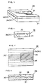
- Fig. 1 is a sketch of a typical example of the prior art optical connector.
- the numeral 10 denotes an optical connector ferrule formed by resin molding;
- a ribbon fiber (A) contains five optical fibers 15 which are fixed in position side by side at a pitch of, say, 0.3 mm, and guide pin holes 16 are formed on both sides of the ribbon fiber at a pitch of 3.6 mm.
- Indicated by 17 is a guide pin having a diameter of, say, 0.7 mm. Two such guide pins 17 are inserted into guide pin holes 16 formed in one optical plug ferrule 10, then inserted into the corresponding holes in the other plug which is positioned in registry with the first plug, and the two optical connectors are coupled together.
- optical connector plug is used to designate the most important basic member of an optical connector which fixes optical fibres in position so as to couple them together.
- optical fibers in one connector should abutt in a very precise manner against those in the other connector in order to minimize the coupling loss.
- This requirement is particularly stringent when coupling single-mode fibers which have a core diameter of only about 10 ⁇ m and even an axial displacement of no more than about 1 ⁇ m between fibers will cause a great coupling loss.
- optical fibers to be mounted on an optical plug must be positioned in the proper place with very high precision; in coupling two optical connectors, it is also necessary that they should be positioned with high precision by means of guide pins.
- optical fiber guide holes and guide pin holes should be provided at designed positions by precision machining. But even if this requirement is met, some clearance still remains both between the optical fiber guide holes and optical fibers and between the guide pin holes and guide pins and because of the existence of such clearance, it is not always possible to achieve low coupling loss. Even if the clearance is only about 0.5 ⁇ m both between optical fibre guide holes and optical fibres and between guide pin holes and guide pins, optical fibres will experience an axial offset of about 1 ⁇ m in an extreme situation.
- each of these clearances be entirely eliminated or substantially reduced to zero.
- guide pins are to be inserted into guide pin holes in a multi-fiber optical connector. If the precision of machining is within ⁇ 1 ⁇ m both for the guide pin diameter which should be 0.700 mm and for the inside diameter of the guide pin hole which should be 0.701 mm, there is a high likelihood that some of the guide pins have an outside diameter of 0.701 mm while some guide pin holes have an inside diameter of 0.700 mm. In this situation, none of the guide pins can be inserted into any guide pin hole.
- a guide pin that is in the form of an elastic slit pipe 18 which has a longitudinal slit 18a as shown in Fig. 3.
- the pipe in order to fabricate a slit pipe having an outside diameter of 0.7 mm with a wall thickness of 0.1 mm, the pipe must be worked to have an inside diameter of 0.5 mm and it is difficult and very expensive to achieve by such micro-machining the precise working of the pipe to attain perfect roundness in its outside diameter and accuracy in other shape parameters.
- the size of guide pins In order to reduce the size of an optical connector, the size of guide pins must also be reduced but to this end, the diameter of each guide pin has to be decreased to 0.5 mm and even to 0.3 mm, making the machining of an elastic slit pipe 18 more and more difficult.
- Document JP-58-88711 describes the manufacturing of a plastic connector comprising a base and a cover being provided with guide grooves for accommodating guide pins.
- the gaps between the pins and the grooves are filled with a silicone rubber.
- the base and the cover as well as the filled rubber are deposited with a metal for manufacturing a high-precision plastic connector.
- document EP-A-0 077 478 relates to an optical fiber connector being provided with identical connector halves both being provided with optical fiber accommodating grooves. For an improved positioning of the optical fibers in the grooves, the latter are provided with supporting rails being made from a soft metal.
- An object of the invention is to provide an optical fibre connector that is free from the aforementioned problems.
- Another object of the invention is to provide an optical fibre connector which is equipped with guide pins that are reduced in diameter and which ensures high dimensional precision and can be produced in large quantities.
- a further object of the invention is to provide an optical fibre connector that tolerates a certain dimensional variation in working due to the limited percision of machining skill and that enables a wire material to be precisely positioned with reduced clearance.
- optical connector with the features of claim 1.
- Advantageous embodiments of the optical connector according to the present invention are defined in the dependent claims.
- the aforementioned object of the present invention can be achieved by providing an optical fibre connector having a filiform material positioning member in which a slit that runs substantially parallel to the axial direction and which communicates with the guide hole is provided either in part of the wall of the guide hole or in the vicinity of the guide hole.
- Fig. 4A is a cross section of a filiform material positioning member according to one specific embodiment of the present invention as it is seen from the front side.
- the wire material positioning member is composed of a grooved substrate 501 having V grooves formed on its top surface and a flat holding plate 502, which are joined to form guide holes 503 in the interior of the assembly through which a wire material (A) is to be inserted.
- Each of the guide holes 503 is provided with four slits 504 that run substantially parallel to the axis of the guide hole 503 and which communicate with the same guide hole 503.
- the wire material (A) inserted into the guide hole 503 makes contact with the wall of the guide hole at three points (a), (b) and (c).
- the wire material (A) also makes contact with part of the two beams 505 that are defined by the four slits 504. Therefore, even if the outside diameter of the wire material (A) is slightly greater than the diameter of the circle that is internally tangent on the guide hole 503, the beams 505 that come in contact with the wire material will deform as shown in Fig. 4B, thereby allowing it to be smoothly inserted into the guide hole 503.
- the slits 504 permit the wall of the guide hole 3 to partly undergo elastic deformation and absorb any slight variation in the diameter of the wire material (A), thereby ensuring three-point supporting of the wire material without leaving any clearance from the guide hole 503.
- each slit 504 may be rounded so as to inhibit the occurrence of cracking in this area.
- slits 504 are provided either in a guide hole 503 or in the vicinity of this hole and the presence of such slits might deteriorate the overall strength of the positioning member.
- the beams 505 which are subject to a large amount of deformation might be affected by a bending stress that is exerted upon the base of the beams 505, or the vicinity of the bottom of slits 504. If a tiny initial crack occurs in this area during machining, it will later develop to a large crack that may eventually destroy the beams 505. Therefore, by rounding the bottom of each slit 504, the occurrence of initial cracking can be prevented to improve the overall strength of the positioning member.
- Fig. 5 is a cross section of a wire material positioning member according to another specific embodiment of the present invention as it is seen from the front side. As shown, some of the slits 504 are filled with a material 507 that has a different elasticity than the material of which the positioning member is made. This embodiment is effective for the purpose of changing the elastic strength of the beams 505. If an external force such as a bending stress is exerted upon the wire material (A) inserted into the guide hole 503, the stress will be propagated to the wall of the guide hole 503 but part of the transmitted stress is absorbed by the elastic deformation of the beams 505. In addition, the strength of the beams can be adjusted by the material 507 filled in the slits 504. Therefore, according to the embodiment shown in Fig. 5, the positioning member is capable of withstanding an external force without breaking and yet the beams can be adjusted to have a capability of undergoing an adequate amount of deformation.
- Fig. 6 is a perspective view of a wire material positioning member according to still another embodiment of the present invention.
- the strength of the beams 505 can also be adjusted by providing an additional slit 508 in a direction substantially perpendicular to the axis of the guide holes 503 as shown in Fig. 3. If more than one slit 508 is provided, the strength of the beam 505 that is present between adjacent slits 508 is determined by the distance from one slit 508 to another. Therefore, the slits 508 are also effective for the purpose of easily adjusting the strength of the beams 505.
- Fig. 7 shows a multi-fiber optical connector which is one example of the application of the wire material positioning member of the present invention.
- the groove substrate 511 and the holding plate 512 which are the two principal components of the multi-fiber optical connector, are each made of silicon which, because of its hard and brittle nature, will not readily deform under external force.
- two guide pin holes 513 and five optical fiber guide holes 514 are formed, and guide pins and optical fibers are inserted into these guide holes 513 and 514, respectively, so that they can be fixed in position in these holes.
- Each of the guide holes 513 is provided with three slits 515 to define two beams 517 and each of the guide holes 514 is also provided with three slits 516 to define two beams 518.
- the guide pins 519 have an outside diameter of 0.35 mm and the optical fibres 520 have an outside diameter of 0.125 mm.
- the guide holes 513 and 514 are so designed that their inside diameters are smaller by a very small amount than the dimensions that permit free insertion of the guide pins 519 and optical fibers 520, respectively.
- the guide pins and optical fibers used in practice have tolerances for their outside diameters but these tolerances are on the order of ⁇ 2 ⁇ m, which can be easily absorbed by the elastic deformation of part of the wall of the guide holes, namely, the beams 517 and 518. Therefore, the optical connector shown in Fig. 7 has the advantage that all of the guide pins and the optical fibers can be reliably supported at three points without leaving any clearance from the guide holes.
- the wire material positioning member of the present invention has no difficulty in absorbing a difference on the order of 2 - 3 ⁇ m and even a hard material like silicon becomes capable of undergoing a certain amount of deformation because of the provision of beams, thereby reducing the clearance between guide holes and the wire material to the smallest possible level.
- the multi-fiber connector of the present invention achieved an average coupling loss of 0.18 dB, and this demonstrates the fact that highly precise positioning can be accomplished by the present invention.
- the position of the slits to be provided in the wire material positioning member of the present invention is by no means limited to part of the wall of guide holes and the slits may be provided in any area in the vicinity of guide holes so long as the slits define beams that are capable of undergoing a small amount of deformation.
- Other parameters of slits, such as their number, width and depth, may also be set to any desired values.
- Figs. 8A to 8C show various slit configurations that can be employed in the present invention.
- Fig. 8A two slits 504 are provided distant form the guide hole 503.
- Fig. 8B a single slit 504 is provided distant form an asymmetric guide hole 503.
- Fig. 8C shows the case where slits 504 having different depths and widths are provided.
- the material of the guide pin may be preferably made of ceramics, particularly of zirconia.
- the zirconia is tougher than alumina, and the outer diameter of the crystal thereof is not larger than 0.5 ⁇ m so that the surface thereof is smooth and slidable.
- At least one of the substrate and the holding plate may be made of silicon as, ceramics, in which the former may be different from the latter in material.
- the filiform material positioning member of the present invention offers the following advantages.
- Figs. 9A to 9D illustrates a specific embodiment of the optical fiber coupling member of the present invention wherein a cover plate 312 placed on top of a grooved substrate 311 that has optical fiber guide grooves 313 and guide pin grooves 314 formed in its top surface is heated at an elevated temperature without employing any adhesive agent so as to produce a unitary assembly which has optical fiber guide holes 313' and guide pin holes 314' formed in its interior.
- a cutout 315 is formed in the rear portion of the cover plate 312 in such a way that part of the optical fiber guide grooves 313 becomes exposed to facilitate subsequent insertion of optical fibers.
- the grooved substrate 311 is joined to the cover plate 312 in the following manner.
- the surfaces of the two members at which they are to be joined together are ground and polished to high dimensional precision and direct bond is temporarily established by wringing; the combination is then heated to an elevated temperature, say, 1,000°C or more so that any impurities, water and other unwanted matter present at the interface between the two members are evaporated to activate their surfaces to such an extent that they are directly bonded together into a unitary assembly.
- a cover plate 312 which is typically made of silicon is joined to a grooved substrate 311 that may also be made of silicon and which has optical fiber guide grooves 313 and guide pin grooves 314 formed in its top surface by machining so as to provide an assembly having optical fiber guide holes 313' and guide pin holes 314' formed in its interior.
- the portion of the cover plate 312 which lies over the rear part of the optical fiber guide grooves 311 is removed to form a cutout 315 so that optical fibers can be easily inserted into the optical fiber guide holes 313'.
- the portion of the cover plate 312 which lies over the guide pin grooves 314 is not removed so that an adhesive agent 318 which is injected in order to securely fix optical fibers in the optical fiber guide holes 313' and grooves 313 will not flow into the guide pin grooves.
- optical fiber guide holes are formed by simply joining a grooved substrate and a cover plate. Therefore, optical fibers can be easily inserted and assembled to provide a coupling member that is capable of positioning optical fibers with dimensional precision.
- a cutout is provided by removing the portion of the cover plate which lies over the rear part of the optical fiber guide grooves and this allows optical fibers to be easily inserted into the optical fiber guide holes. If, in this case, the portion of the cover plate which lies over the guide pin grooves is left intact (i.e., remains bonded to the grooved substrate), it can be ensured that an adhesive agent used in order to fix optical fibers will not flow out of the system or flow into the guide pin grooves.
- part of the optical connector ferrule 401 is cut out so that part of the guide pin holes 402 is exposed in that area indicated by 403.
- the guide pins will also become exposed in the area 403 where the guide pin holes are exposed.
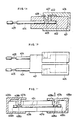
- Fig. 12 is a side view showing one example of the guide pin 404 used in coupling optical connectors according to the present invention.
- the guide pin 404 is provided with a recess 405 in that portion which is to be situated in the area 403 when it is inserted into a guide pin hole 402 in the connector ferrule 401 shown in Figs. 11A to 11C.
- the guide pin 404 can be secured in position by causing a clamp mechanism to act in the recess in the manner to be described later in this specification. It is not always necessary to provide the recess 405 and if it is not provided, the guide pin may be clamped by allowing the necessary amount of lateral pressure to act on the pin.
- Figs. 13A and 13B illustrate a specific embodiment of the ferrule of the present invention into which guide pins have been inserted and which is equipped with a clamp mechanism.
- Fig. 13A is a longitudinal section and Fig. 13B is a top view.
- the optical connector ferrule 401 is provided with a flange 406 in its rear portion and this flange 406 has a clamp mechanism as an integral part thereof.
- the top of the flange 406 provides an elastic beam 407 from which a plunger 408 projects downwardly.
- the plunger 408 moves downward until it contacts the bottom of the recess 405 in the guide pin 404.
- the optical connector is disconnected after the plunger has been urged into contact with the bottom of the recess 405, so the guide pins 404 are always left behind in the connector ferrule that has this urged elastic beam.
- Fig. 14 is a longitudinal section of two optical connector ferrules 401a and 401b that have been coupled together end to end by means of guide pins 404.
- the connector ferrules 401a and 401b are equipped with flanges 406a and 406b having elastic beams 407a and 407b, respectively.
- the elastic beam 407a shown on the right-hand side of Fig. 14 is urged downward to bring the plunger 408a into contact with the bottom of recess 405a in the guide pin 404.
- the other elastic beam 407b is not urged, so the plunger 408b remains distant from the bottom of the other recess 405b in the guide pin 404. If the connector ferrule 401a under this condition is disconnected from the other ferrule 401b, the guide pin 404 is sure to be left behind in the ferrule 401a which is shown on the right-hand side of Fig. 14.
- Figs. 15A to 15C show other embodiments of the area where the guide pin holes are exposed.
- Fig. 15A shows an optical connector ferrule in which a silicon top plate 411 is stacked on a grooved silicon substrate 410 having optical fiber guide grooves and guide pin grooves formed in its top surface and the two members are joined together with an interposing thin layer of an adhesive agent so as to form optical fiber guide holes 413 and guide pin holes 412.
- cutouts 414 are formed in part of the top plate 411 so that part of the guide pin grooves is exposed in those areas, and plungers are caused to move downward in such a way that they contact the bottom of the exposed areas 414 to clamp the guide pins.
- Fig. 15B shows an embodiment in which an optical connector ferrule is formed by joining a grooved silicon substrate 410 and a top silicon plate 411 as in the case shown in Fig. 15A.
- part of the guide pin holes 412 is made exposed by entirely removing the rear portion of the top plate 411.
- a step portion 415 provided in the rear portion of the grooved substrate 410 serves as an area for fixing an array of optical fibers in position.
- Fig. 15C shows the case of employing a guide pin 404 that is longer than the optical connector ferrule; in this embodiment, the portion 416 that projects form the rear end of the ferrule is used as the area where the guide pin is exposed.
- an area where guide pin holes are exposed is provided in part of the optical connector ferrule in such a way that the guide pins will become exposed in this area. If this configuration is combined with a clamp mechanism, the operator can disconnect and connect optical connector ferrules while having exact knowledge as to in which ferrule the guide pins have been left behind.
- FIGs. 13A, 13B and 14 An example of the clamp mechanism that performs its function by exerting pressure is shown in Figs. 13A, 13B and 14 but depending upon the specific use or dimensions of the connector ferrule, various modifications can be made without departing from the scope of the present invention by introducing some special features into the design of the flange to be mounted on the ferrule or of the housing of the connector plug.
- the clearance that would occur between the guide pins and the guide pin holes which are to be coupled thereto is entirely eliminated or reduced to a very small value, thereby realizing low-loss coupling of optical fibers in a consistent manner.
- the optical connector ferrules of the present invention can be precisely and easily disconnected or connected.
Landscapes
- Physics & Mathematics (AREA)
- General Physics & Mathematics (AREA)
- Optics & Photonics (AREA)
- Chemical & Material Sciences (AREA)
- Crystallography & Structural Chemistry (AREA)
- Mechanical Coupling Of Light Guides (AREA)
Claims (8)
- Connecteur optique, comprenant :un élément connecteur de fibres optiques qui comporte une plaque (501) de substrat ayant au moins une gorge de fibre optique et des gorges de broche, formées chacune dans une surface de la plaque, et une plaque de couvercle (502) raccordée à la plaque de substrat pour la formation de trous (503) de gorges destinées à des broches et d'au moins un trou de gorge destinée à une fibre optique afin qu'une fibre optique puisse être introduite,un dispositif à broches destiné à pénétrer dans les trous des gorges pour broches pour le couplage de l'élément connecteur de fibres optiques à un autre élément, etun dispositif destiné à compenser la variation de diamètre du dispositif à broches et de la fibre optique au moins,caractérisé en ce queles plaques de substrat et de couvercle (502) sont formées d'un matériau dur, tel que le silicium ou une céramique, facilitant le positionnement de la fibre optique au moins et du dispositif à broches,la plaque de couvercle (502) a une surface plane pratiquement plate tournée vers le substrat (501),l'une au moins parmi les gorges destinées à la fibre optique et aux broches a au moins une fente (504) qui est sensiblement parallèle à la direction axiale de sa gorge respective, la fente au moins faisant partie de la gorge respective et étant disposée afin qu'elle délimite au moins un organe (505) sous forme d'une poutre flexible en porte-à-faux utilisé comme dispositif de compensation, si bien que la fibre est supportée en trois points autour de sa circonférence.
- Connecteur optique selon la revendication 1, dans lequel le dispositif à broches est formé de céramique.
- Connecteur optique selon la revendication 1, dans lequel le dispositif à broches est formé de zircone.
- Connecteur optique selon la revendication 1, dans lequel l'une au moins des plaques de substrat et de couvercle est formée de silicium.
- Connecteur optique selon la revendication 1, dans lequel l'une au moins des plaques de substrat et de couvercle est formée de céramique.
- Connecteur optique selon la revendication 1, dans lequel la plaque de couvercle est liée chimiquement à la plaque de substrat sans matière adhésive.
- Connecteur optique selon la revendication 6, dans lequel la plaque de couvercle et la plaque de substrat sont formées de silicium, la première étant raccordée à la seconde par des liaison Si-O-Si.
- Connecteur optique selon la revendication 5, dans lequel la plaque de couvercle et la plaque de substrat sont formées de silicium, la première étant raccordée à la seconde par des liaisons Si-Si.
Applications Claiming Priority (15)
| Application Number | Priority Date | Filing Date | Title |
|---|---|---|---|
| JP27253886A JPS63125908A (ja) | 1986-11-15 | 1986-11-15 | 光コネクタ |
| JP272538/86 | 1986-11-15 | ||
| JP288539/86 | 1986-12-03 | ||
| JP61288539A JPS63141005A (ja) | 1986-12-03 | 1986-12-03 | 光コネクタ |
| JP876187A JPH0786575B2 (ja) | 1987-01-16 | 1987-01-16 | 光フアイバ結合部材 |
| JP8761/87 | 1987-01-16 | ||
| JP7528587A JPS63240509A (ja) | 1987-03-27 | 1987-03-27 | 線材位置決め部材 |
| JP75285/87 | 1987-03-27 | ||
| JP114236/87 | 1987-05-11 | ||
| JP62114236A JP2569329B2 (ja) | 1987-05-11 | 1987-05-11 | 光コネクタ |
| JP224373/87 | 1987-09-08 | ||
| JP62224373A JPH07104459B2 (ja) | 1987-09-08 | 1987-09-08 | 光ファイバ結合部材及びその製造方法 |
| JP22942087A JPS6472104A (en) | 1987-09-11 | 1987-09-11 | Optical fiber coupling member |
| JP229420/87 | 1987-09-11 | ||
| EP87116804A EP0271721B1 (fr) | 1986-11-15 | 1987-11-13 | Connecteur optique et son procédé de fabrication |
Related Parent Applications (1)
| Application Number | Title | Priority Date | Filing Date |
|---|---|---|---|
| EP87116804.3 Division | 1987-11-13 |
Publications (3)
| Publication Number | Publication Date |
|---|---|
| EP0482673A2 EP0482673A2 (fr) | 1992-04-29 |
| EP0482673A3 EP0482673A3 (en) | 1992-11-19 |
| EP0482673B1 true EP0482673B1 (fr) | 1997-06-11 |
Family
ID=27563467
Family Applications (3)
| Application Number | Title | Priority Date | Filing Date |
|---|---|---|---|
| EP90116010A Expired - Lifetime EP0405620B1 (fr) | 1986-11-15 | 1987-11-13 | Procédé pour la fabrication d'un connecteur optique |
| EP91121375A Expired - Lifetime EP0482673B1 (fr) | 1986-11-15 | 1987-11-13 | Connecteur optique |
| EP87116804A Expired - Lifetime EP0271721B1 (fr) | 1986-11-15 | 1987-11-13 | Connecteur optique et son procédé de fabrication |
Family Applications Before (1)
| Application Number | Title | Priority Date | Filing Date |
|---|---|---|---|
| EP90116010A Expired - Lifetime EP0405620B1 (fr) | 1986-11-15 | 1987-11-13 | Procédé pour la fabrication d'un connecteur optique |
Family Applications After (1)
| Application Number | Title | Priority Date | Filing Date |
|---|---|---|---|
| EP87116804A Expired - Lifetime EP0271721B1 (fr) | 1986-11-15 | 1987-11-13 | Connecteur optique et son procédé de fabrication |
Country Status (6)
| Country | Link |
|---|---|
| US (1) | US4830456A (fr) |
| EP (3) | EP0405620B1 (fr) |
| KR (1) | KR880006559A (fr) |
| AU (1) | AU601240B2 (fr) |
| CA (1) | CA1302758C (fr) |
| DE (3) | DE3786900T2 (fr) |
Families Citing this family (96)
| Publication number | Priority date | Publication date | Assignee | Title |
|---|---|---|---|---|
| CA1283569C (fr) * | 1986-03-14 | 1991-04-30 | Toshiaki Kakii | Raccord et dispositif pour epissure de fibres optiques |
| US5000537A (en) * | 1989-05-25 | 1991-03-19 | Kabushiki Kaisha Nippon Optolonics Kenkyusho | Sleeve for an optical fiber connector and fabricating method therefor |
| US4973127A (en) * | 1989-05-31 | 1990-11-27 | At&T Bell Laboratories | Multifiber optical connector and method of making same |
| JP2590266B2 (ja) * | 1989-06-23 | 1997-03-12 | 住友電気工業株式会社 | 光コネクタ |
| IT1240310B (it) * | 1989-07-24 | 1993-12-07 | Pirelli Cavi Spa | Gruppo di connessione separabile per fibre ottiche riunite a nastro e relativo metodo di realizzazione. |
| US5243673A (en) * | 1989-08-02 | 1993-09-07 | E. I. Du Pont De Nemours And Company | Opto-electronic component having positioned optical fiber associated therewith |
| GB2237121B (en) * | 1989-10-10 | 1993-07-21 | Bowthorpe Hellermann Ltd | Optical fibre splice storage enclosure |
| US4998796A (en) * | 1990-02-27 | 1991-03-12 | At&T Bell Laboratories | Method of assembling multi-grooved silicon chip fiber optic terminations |
| US5082346A (en) * | 1990-06-28 | 1992-01-21 | At&T Bell Laboratories | Field-assemblable multifiber optical connector |
| FR2680879B1 (fr) * | 1991-08-30 | 1994-12-30 | Alsthom Cge Alcatel | Procede de fabrication d'ebauches de ferrules ou de multiferrules, et ebauches obtenues par ce procede. |
| US5078467A (en) * | 1991-02-07 | 1992-01-07 | Minnesota Mining And Manufacturing Company | Optical fiber connector including integral deformable housing and second-class levers |
| GB9104951D0 (en) * | 1991-03-08 | 1991-04-24 | Bicc Plc | Optical fibre fusion splicing |
| US5091988A (en) * | 1991-04-12 | 1992-02-25 | At&T Bell Laboratories | Article for connecting optical fibers |
| AU649162B2 (en) * | 1991-08-17 | 1994-05-12 | Nippon Telegraph & Telephone Corporation | Optical connector |
| US5155781A (en) * | 1991-09-06 | 1992-10-13 | Minnesota Mining And Manufacturing Company | Multiple optical fiber splice with sealing end covers |
| CA2077856C (fr) * | 1991-09-09 | 2000-02-15 | Toshiaki Kakii | Connecteur optique |
| SE500945C2 (sv) * | 1992-05-19 | 1994-10-03 | Stiftelsen Inst Foer Mikroelek | Skarvdon för ljusfibrer |
| US5422971A (en) * | 1993-02-02 | 1995-06-06 | Sumitomo Electric Industries, Ltd. | Optical fiber connector using adhesive |
| CA2135758A1 (fr) * | 1993-03-31 | 1994-10-01 | Toshiaki Kakii | Reseau de fibres optiques |
| DE4322660C2 (de) * | 1993-07-07 | 1996-09-12 | Hirschmann Richard Gmbh Co | Vorrichtung zum Zentrieren von Lichtwellenleitern aufeinander |
| DE4423842C2 (de) * | 1993-07-07 | 1997-04-30 | Hirschmann Richard Gmbh Co | Steckverbinder für Lichtwellenleiter und Formeinsatz zur Herstellung desselben |
| US5345323A (en) * | 1993-08-02 | 1994-09-06 | At&T Bell Laboratories | Techniques for polishing optical fiber ends |
| US5664039A (en) * | 1994-06-08 | 1997-09-02 | The Whitaker Corporation | High density fiber ferrules and connectors |
| AU3490095A (en) * | 1994-07-18 | 1996-02-16 | Sang K. Sheem | Face-lock interconnection means for optical fibers and other optical components, and manufacturing methods of the same |
| US5633968A (en) * | 1994-07-18 | 1997-05-27 | Sheem; Sang K. | Face-lock interconnection means for optical fibers and other optical components and manufacturing methods of the same |
| US5550942A (en) * | 1994-07-18 | 1996-08-27 | Sheem; Sang K. | Micromachined holes for optical fiber connection |
| JP3345518B2 (ja) * | 1994-09-28 | 2002-11-18 | 株式会社東芝 | 光半導体モジュールの製造方法 |
| SE9403574L (sv) * | 1994-10-19 | 1996-04-20 | Ericsson Telefon Ab L M | Optokomponentkapsel med optiskt gränssnitt |
| US5604830A (en) * | 1994-12-22 | 1997-02-18 | Hoechst Celanese Corp. | Multiple fiber connector for injection molded multiple fiberoptic coupler unit and cladding for same |
| US6254280B1 (en) * | 1995-02-21 | 2001-07-03 | Agere Systems Optoelectronics Guardian Corp. | Substrate based array connector |
| JPH08234056A (ja) * | 1995-02-28 | 1996-09-13 | Sumitomo Electric Ind Ltd | 光コネクタ |
| US5559915A (en) * | 1995-04-13 | 1996-09-24 | Lucent Technologies Inc. | Apparatuses and methods for aligning an optical fiber array with an optical integrated circuit assembly |
| US5790731A (en) * | 1995-04-13 | 1998-08-04 | Lucent Technologies Inc. | Optical fiber array/optical integrated circuit interconnection assembly and enclosures for protecting the interconnection assembly |
| JP2966329B2 (ja) * | 1995-10-11 | 1999-10-25 | 古河電気工業株式会社 | 多心コネクタ |
| US5613024A (en) * | 1995-12-21 | 1997-03-18 | Lucent Technologies Inc. | Alignment of optical fiber arrays to optical integrated circuits |
| US6045270A (en) | 1995-12-22 | 2000-04-04 | Methode Electronics, Inc. | Massive parallel optical interconnect system |
| US5737463A (en) * | 1995-12-22 | 1998-04-07 | Weiss; Roger E. | Massive parallel optical interconnect system |
| US6367985B1 (en) * | 1996-03-12 | 2002-04-09 | Intellectual Property Company | Optical connector using large diameter alignment features |
| US6805493B2 (en) | 1996-03-12 | 2004-10-19 | 3M Innovative Properties Company | Optical connector assembly using partial large diameter alignment features |
| EP0800100A1 (fr) * | 1996-04-04 | 1997-10-08 | US Conec Ltd | Assemblage d'embout pour l'insertion sans jeu d'une tige de guidage |
| US5815621A (en) * | 1996-05-23 | 1998-09-29 | Sumitomo Electric Industries, Ltd. | Optical fiber connector ferrule with die and method of manufacturing same |
| JP3274972B2 (ja) * | 1996-07-31 | 2002-04-15 | 京セラ株式会社 | 光学素子保持部材の製造方法 |
| GB2313676B (en) * | 1997-03-07 | 1998-04-08 | Bookham Technology Ltd | Attachment of an optical fibre |
| US6160947A (en) * | 1997-03-27 | 2000-12-12 | Nck Insulators, Ltd. | Optical transmission member-fixed assembly |
| GB2330424B (en) * | 1997-11-21 | 1999-09-08 | Bookham Technology Ltd | Apparatus for connecting an optical fibre to an optical device |
| JPH11242128A (ja) * | 1997-12-26 | 1999-09-07 | Ngk Insulators Ltd | 熱融着一体型フェルールとその製造方法、ファイバーアレイの製造方法 |
| US6328482B1 (en) * | 1998-06-08 | 2001-12-11 | Benjamin Bin Jian | Multilayer optical fiber coupler |
| US6454464B1 (en) | 1998-12-28 | 2002-09-24 | Computer Crafts, Inc. | Fiber optic connectors and transceiver test devices |
| US6464408B1 (en) | 1998-12-28 | 2002-10-15 | Computer Crafts, Inc. | Fiber optic connectors |
| US6447171B1 (en) * | 2000-02-04 | 2002-09-10 | Fci Americas Technology, Inc | Multi-fiber array connector system |
| US6595698B2 (en) | 2000-06-13 | 2003-07-22 | Siwave, Inc. | High density fiber terminator/connector |
| US6450697B1 (en) | 2000-08-24 | 2002-09-17 | Berg Technology, Inc. | Optical connector having a combined guide pin lock and grounding contact |
| US20020141725A1 (en) * | 2001-03-16 | 2002-10-03 | Zolo Technologies, Inc. | Fiber pigtail template assembly |
| US7167499B2 (en) * | 2001-04-18 | 2007-01-23 | Tcz Pte. Ltd. | Very high energy, high stability gas discharge laser surface treatment system |
| JP3631445B2 (ja) * | 2001-06-06 | 2005-03-23 | 東芝三菱電機産業システム株式会社 | 平型半導体スタック装置 |
| US6669377B2 (en) | 2001-06-11 | 2003-12-30 | Corning Cable Systems Llc | Fiber optic connector and an associated pin retainer |
| US7036993B2 (en) | 2001-06-11 | 2006-05-02 | Corning Cable Systems Llc | Pin retainer for fiber optic connector and associated fabrication method |
| US6695488B2 (en) * | 2001-07-19 | 2004-02-24 | Cinch Connectors, Inc. | Tool and method for forming a multi fiber ferrule |
| US6736546B2 (en) | 2001-08-31 | 2004-05-18 | Teradyne, Inc. | Optical connector ferrule designed to minimize manufacturing imperfections and mating misalignments by incorporating exact constraint principles |
| US6742937B2 (en) | 2001-12-18 | 2004-06-01 | 3M Innovative Properties Company | Optical fiber connector having compliant alignment features |
| US7095922B2 (en) * | 2002-03-26 | 2006-08-22 | Ngk Insulators, Ltd. | Lensed fiber array and production method thereof |
| JP3788967B2 (ja) | 2002-09-27 | 2006-06-21 | 日本航空電子工業株式会社 | 光コネク夕 |
| DE10304977B4 (de) * | 2003-02-07 | 2006-06-29 | Protron Mikrotechnik Gmbh | Vorrichtung zur Positionierung optischer Fasern, Verbinder mit derartiger Vorrichtung sowie optisches Kabel mit derartigen Verbinder |
| US6973242B2 (en) * | 2003-04-17 | 2005-12-06 | 3M Innovative Properties Company | Apparatus useful for guiding fiber optic ribbons into ferrules |
| US7108431B2 (en) * | 2003-04-17 | 2006-09-19 | 3M Innovative Properties Company | Ferrule for use in fiber optic connectors |
| EP1761813B1 (fr) * | 2004-06-30 | 2014-06-25 | Hoya Corporation Usa | Dispositif optique couple a des fibres |
| CN100356221C (zh) * | 2005-12-30 | 2007-12-19 | 武汉海博光技术有限公司 | 光纤阵列组件中光纤排放封装设备 |
| US7543993B2 (en) | 2006-03-03 | 2009-06-09 | Hoya Corporation Usa | Fiber-coupled optical device mounted on a circuit board |
| TWM379765U (en) * | 2009-10-12 | 2010-05-01 | Hon Hai Prec Ind Co Ltd | Optical-fiber connector and assembly |
| CN102053311B (zh) * | 2009-10-27 | 2014-01-15 | 鸿富锦精密工业(深圳)有限公司 | 光纤耦合连接器 |
| TWI453479B (zh) * | 2009-11-04 | 2014-09-21 | Hon Hai Prec Ind Co Ltd | 光纖耦合連接器 |
| US8768125B2 (en) * | 2010-04-26 | 2014-07-01 | Corning Cable Systems Llc | Guide pin for aligning ferrules with enhanced alignment feature |
| US9529159B2 (en) * | 2010-07-30 | 2016-12-27 | Corning Optical Communications LLC | Ferrules with complementary mating geometry and related fiber optic connectors |
| US10401572B2 (en) | 2010-07-30 | 2019-09-03 | Corning Optical Communications, Llc | Fiber optic connectors including ferrules with complementary mating geometry and related fiber optic connectors |
| TWI510830B (zh) * | 2010-12-14 | 2015-12-01 | Hon Hai Prec Ind Co Ltd | 光纖耦合連接器 |
| CN102540347B (zh) * | 2010-12-16 | 2015-07-01 | 鸿富锦精密工业(深圳)有限公司 | 光纤耦合连接器及其组装方法 |
| CN102565953B (zh) * | 2010-12-16 | 2015-04-15 | 鸿富锦精密工业(深圳)有限公司 | 光纤耦合连接器 |
| CA2832182C (fr) * | 2011-04-05 | 2018-01-16 | Nanoprecision Products, Inc. | Ferrule de connecteur a fibres optiques ayant des rainures ouvertes pour le serrage des fibres |
| JP5715916B2 (ja) * | 2011-09-16 | 2015-05-13 | 株式会社フジクラ | フェルール、光ファイバ付きフェルール、光コネクタ |
| JP5564026B2 (ja) * | 2011-10-18 | 2014-07-30 | 株式会社フジクラ | 光ファイバテープ心線及びその光ファイバテープ心線を収納した光ファイバケーブル |
| CN104380161B (zh) * | 2012-04-05 | 2017-05-24 | 纳米精密产品股份有限公司 | 具有用于夹持对准销的柔顺结构的用于光纤连接器的套箍 |
| US10564363B1 (en) * | 2013-03-15 | 2020-02-18 | Wavefront Research, Inc. | Optical connectors |
| US9304264B2 (en) * | 2013-04-26 | 2016-04-05 | Tyco Electronics Corporation | Optical fiber subassembly |
| CN104181645B (zh) * | 2013-05-28 | 2016-06-01 | 泰科电子(上海)有限公司 | 校准工具、校准方法、光纤插芯组件和光纤连接器 |
| CN104181644B (zh) * | 2013-05-28 | 2016-07-06 | 泰科电子(上海)有限公司 | 对准工具、对准方法、光纤插芯组件和光纤连接器 |
| JP6278627B2 (ja) * | 2013-07-18 | 2018-02-14 | 富士通コンポーネント株式会社 | 光モジュール |
| US9690054B2 (en) * | 2013-07-31 | 2017-06-27 | Nanoprecision Products, Inc. | Foldover optical fiber ferrule assembly |
| US9182554B2 (en) * | 2013-11-27 | 2015-11-10 | Avago Technologies General Ip (Singapore) Pte. Ltd. | Optical connector having improved guide pin retention |
| CN105445864B (zh) | 2014-07-01 | 2017-12-05 | 泰科电子(上海)有限公司 | 插芯组件和插芯器件 |
| CN107608032B (zh) | 2014-07-01 | 2019-12-20 | 泰科电子(上海)有限公司 | 光纤对准装置、插芯器件和插芯器件的制造方法 |
| WO2017066022A1 (fr) * | 2015-10-12 | 2017-04-20 | 3M Innovative Properties Company | Élément de positionnement de guide d'ondes optiques dans un connecteur de guides d'ondes multiples |
| US10197746B2 (en) | 2015-12-18 | 2019-02-05 | US Conec, Ltd | Fiber optic ferrule and a guide pin clamp with field changeable guide pins |
| CN107918174A (zh) | 2016-10-11 | 2018-04-17 | 康普技术有限责任公司 | 插芯组件、制造插芯组件的方法及光纤固定模具 |
| WO2018125706A1 (fr) * | 2016-12-29 | 2018-07-05 | Corning Optical Communications LLC | Botte de ferrule avec canal de guidage (s) pour ferrule multifibre et procédé de fabrication l'utilisant |
| JP6462833B1 (ja) * | 2017-11-16 | 2019-01-30 | 株式会社フジクラ | フェルール構造体及びフェルール構造体の製造方法 |
| WO2020235041A1 (fr) * | 2019-05-22 | 2020-11-26 | 日本電信電話株式会社 | Structure de connexion de guide d'ondes, puce de guide d'ondes, connecteur, procédé de fabrication de composant de connexion de guide d'ondes, et procédé de connexion de gude d'ondes |
Citations (1)
| Publication number | Priority date | Publication date | Assignee | Title |
|---|---|---|---|---|
| EP0009117A1 (fr) * | 1978-09-14 | 1980-04-02 | Siemens Aktiengesellschaft | Connexion détachable, notamment fiche de connexion pour le raccordement d'au moins deux guides d'ondes optiques |
Family Cites Families (12)
| Publication number | Priority date | Publication date | Assignee | Title |
|---|---|---|---|---|
| GB1520679A (en) * | 1977-02-18 | 1978-08-09 | Bicc Ltd | Jointing optical fibres |
| FR2406211A1 (fr) * | 1977-10-17 | 1979-05-11 | Radiall Sa | Procede et dispositif de raccordement de fibres optiques |
| US4253730A (en) * | 1977-11-17 | 1981-03-03 | Thomas & Betts Corporation | Optical fiber connector |
| CH628152A5 (fr) * | 1977-11-24 | 1982-02-15 | Comp Generale Electricite | Fiche de connecteur fibre a fibre pour cable optique multifibre. |
| FR2415314A1 (fr) * | 1978-01-19 | 1979-08-17 | Souriau & Cie | Module de connexion pour conducteurs optiques monobrins et connecteur muni de tels modules |
| FR2427622A1 (fr) * | 1978-05-30 | 1979-12-28 | Lyonnaise Transmiss Optiques | Procede de raccordement de fibres optiques disposees en nappe dans un cable, et dispositif de mise en oeuvre du procede |
| JPS5548717A (en) * | 1978-10-05 | 1980-04-08 | Nippon Telegr & Teleph Corp <Ntt> | Manufacture of multicore connector plate of optical fiber |
| JPS57139716A (en) * | 1981-02-24 | 1982-08-28 | Nippon Telegr & Teleph Corp <Ntt> | Device and method for connection of optical fiber |
| US4458985A (en) * | 1981-10-16 | 1984-07-10 | International Business Machines Corporation | Optical fiber connector |
| JPS5888711A (ja) * | 1981-11-24 | 1983-05-26 | Nippon Telegr & Teleph Corp <Ntt> | 多心光フアイバ用プラスチツクコネクタの金型製作方法 |
| DE3443693A1 (de) * | 1984-11-30 | 1986-06-05 | Standard Elektrik Lorenz Ag, 7000 Stuttgart | Optische steckverbindung mit zentrieranordnung und verfahren zur herstellung solcher zentrieranordnungen |
| CA1283569C (fr) * | 1986-03-14 | 1991-04-30 | Toshiaki Kakii | Raccord et dispositif pour epissure de fibres optiques |
-
1987
- 1987-11-13 EP EP90116010A patent/EP0405620B1/fr not_active Expired - Lifetime
- 1987-11-13 DE DE87116804T patent/DE3786900T2/de not_active Expired - Fee Related
- 1987-11-13 US US07/120,521 patent/US4830456A/en not_active Expired - Fee Related
- 1987-11-13 DE DE3752078T patent/DE3752078T2/de not_active Expired - Fee Related
- 1987-11-13 EP EP91121375A patent/EP0482673B1/fr not_active Expired - Lifetime
- 1987-11-13 EP EP87116804A patent/EP0271721B1/fr not_active Expired - Lifetime
- 1987-11-13 DE DE3751810T patent/DE3751810T2/de not_active Expired - Fee Related
- 1987-11-13 CA CA000551847A patent/CA1302758C/fr not_active Expired - Fee Related
- 1987-11-14 KR KR870012843A patent/KR880006559A/ko not_active Application Discontinuation
- 1987-11-16 AU AU81263/87A patent/AU601240B2/en not_active Ceased
Patent Citations (1)
| Publication number | Priority date | Publication date | Assignee | Title |
|---|---|---|---|---|
| EP0009117A1 (fr) * | 1978-09-14 | 1980-04-02 | Siemens Aktiengesellschaft | Connexion détachable, notamment fiche de connexion pour le raccordement d'au moins deux guides d'ondes optiques |
Also Published As
| Publication number | Publication date |
|---|---|
| EP0405620B1 (fr) | 1996-05-15 |
| EP0271721A3 (en) | 1988-12-07 |
| DE3786900T2 (de) | 1993-11-11 |
| DE3751810D1 (de) | 1996-06-20 |
| EP0405620A2 (fr) | 1991-01-02 |
| EP0482673A3 (en) | 1992-11-19 |
| CA1302758C (fr) | 1992-06-09 |
| EP0482673A2 (fr) | 1992-04-29 |
| KR880006559A (ko) | 1988-07-23 |
| DE3786900D1 (de) | 1993-09-09 |
| EP0271721B1 (fr) | 1993-08-04 |
| AU601240B2 (en) | 1990-09-06 |
| US4830456A (en) | 1989-05-16 |
| AU8126387A (en) | 1988-05-19 |
| EP0271721A2 (fr) | 1988-06-22 |
| DE3752078D1 (de) | 1997-07-17 |
| EP0405620A3 (en) | 1992-05-06 |
| DE3751810T2 (de) | 1996-09-26 |
| DE3752078T2 (de) | 1997-09-18 |
Similar Documents
| Publication | Publication Date | Title |
|---|---|---|
| EP0482673B1 (fr) | Connecteur optique | |
| US5613024A (en) | Alignment of optical fiber arrays to optical integrated circuits | |
| CA1314161C (fr) | Connecteur optique | |
| EP1664871B1 (fr) | Ferrule optique | |
| EP0241724B1 (fr) | Connecteur optique et épissure | |
| EP1584959B1 (fr) | Procédé de connection des fibres optiques et des components optiques usant des courbures des fibres optiques | |
| AU742671B2 (en) | Massive parallel optical interconnect system | |
| US4201444A (en) | Single optical fiber connector | |
| US7325979B2 (en) | Method for releasably connecting two groups of optical fibers, and plug-in connector for carrying out said method | |
| US6256448B1 (en) | Stackable multi-fiber ferrule assembly methods and tools | |
| KR0171384B1 (ko) | 리본형 광케이블용 다심 광커넥터 | |
| EP0926520B1 (fr) | Matrice de fibres optiques | |
| US6769811B2 (en) | Multi-fiber optic device | |
| WO1990007137A1 (fr) | Ferrure de connexion de fibres optiques et connecteur optique l'utilisant | |
| US6402390B1 (en) | V-groove adapters for interconnecting optical conductors | |
| US20030133689A1 (en) | Optical fiber block having holding sub-block | |
| JP3316718B2 (ja) | 光コネクタおよび光導波回路 | |
| WO2003041129A2 (fr) | Extremite de fibre optique | |
| EP0642675B1 (fr) | Dispositif de connexion pour fibres optiques | |
| JPH0583883B2 (fr) | ||
| JP3218262B2 (ja) | 光導波路部品 | |
| JPH08160242A (ja) | 光ファイバアレイ | |
| KR0162751B1 (ko) | 다심 광커넥터 | |
| JPH08313762A (ja) | 光コネクタプラグ | |
| JPH0735940A (ja) | 光導波路部品及び光導波路部品の製造方法 |
Legal Events
| Date | Code | Title | Description |
|---|---|---|---|
| PUAI | Public reference made under article 153(3) epc to a published international application that has entered the european phase |
Free format text: ORIGINAL CODE: 0009012 |
|
| 17P | Request for examination filed |
Effective date: 19911212 |
|
| AC | Divisional application: reference to earlier application |
Ref document number: 271721 Country of ref document: EP |
|
| AK | Designated contracting states |
Kind code of ref document: A2 Designated state(s): DE FR GB IT SE |
|
| PUAL | Search report despatched |
Free format text: ORIGINAL CODE: 0009013 |
|
| AK | Designated contracting states |
Kind code of ref document: A3 Designated state(s): DE FR GB IT SE |
|
| 17Q | First examination report despatched |
Effective date: 19940505 |
|
| GRAG | Despatch of communication of intention to grant |
Free format text: ORIGINAL CODE: EPIDOS AGRA |
|
| GRAH | Despatch of communication of intention to grant a patent |
Free format text: ORIGINAL CODE: EPIDOS IGRA |
|
| GRAH | Despatch of communication of intention to grant a patent |
Free format text: ORIGINAL CODE: EPIDOS IGRA |
|
| GRAA | (expected) grant |
Free format text: ORIGINAL CODE: 0009210 |
|
| AC | Divisional application: reference to earlier application |
Ref document number: 271721 Country of ref document: EP |
|
| AK | Designated contracting states |
Kind code of ref document: B1 Designated state(s): DE FR GB IT SE |
|
| PG25 | Lapsed in a contracting state [announced via postgrant information from national office to epo] |
Ref country code: FR Free format text: THE PATENT HAS BEEN ANNULLED BY A DECISION OF A NATIONAL AUTHORITY Effective date: 19970611 |
|
| REF | Corresponds to: |
Ref document number: 3752078 Country of ref document: DE Date of ref document: 19970717 |
|
| ET | Fr: translation filed | ||
| PG25 | Lapsed in a contracting state [announced via postgrant information from national office to epo] |
Ref country code: GB Free format text: LAPSE BECAUSE OF NON-PAYMENT OF DUE FEES Effective date: 19971113 |
|
| PG25 | Lapsed in a contracting state [announced via postgrant information from national office to epo] |
Ref country code: SE Free format text: LAPSE BECAUSE OF NON-PAYMENT OF DUE FEES Effective date: 19971114 |
|
| PLBE | No opposition filed within time limit |
Free format text: ORIGINAL CODE: 0009261 |
|
| STAA | Information on the status of an ep patent application or granted ep patent |
Free format text: STATUS: NO OPPOSITION FILED WITHIN TIME LIMIT |
|
| 26N | No opposition filed | ||
| GBPC | Gb: european patent ceased through non-payment of renewal fee |
Effective date: 19971113 |
|
| PG25 | Lapsed in a contracting state [announced via postgrant information from national office to epo] |
Ref country code: DE Free format text: LAPSE BECAUSE OF NON-PAYMENT OF DUE FEES Effective date: 19980801 |
|
| EUG | Se: european patent has lapsed |
Ref document number: 91121375.9 |
|
| REG | Reference to a national code |
Ref country code: FR Ref legal event code: ST |
|
| PG25 | Lapsed in a contracting state [announced via postgrant information from national office to epo] |
Ref country code: IT Free format text: LAPSE BECAUSE OF NON-PAYMENT OF DUE FEES Effective date: 20051113 |