EP0481426B1 - Presswerkzeugkontrollmechanismen für Form-Presswerkzeuge - Google Patents
Presswerkzeugkontrollmechanismen für Form-Presswerkzeuge Download PDFInfo
- Publication number
- EP0481426B1 EP0481426B1 EP91117576A EP91117576A EP0481426B1 EP 0481426 B1 EP0481426 B1 EP 0481426B1 EP 91117576 A EP91117576 A EP 91117576A EP 91117576 A EP91117576 A EP 91117576A EP 0481426 B1 EP0481426 B1 EP 0481426B1
- Authority
- EP
- European Patent Office
- Prior art keywords
- toggle
- machine
- ram
- during
- positions
- Prior art date
- Legal status (The legal status is an assumption and is not a legal conclusion. Google has not performed a legal analysis and makes no representation as to the accuracy of the status listed.)
- Expired - Lifetime
Links
Images


Classifications
-
- H—ELECTRICITY
- H01—ELECTRIC ELEMENTS
- H01R—ELECTRICALLY-CONDUCTIVE CONNECTIONS; STRUCTURAL ASSOCIATIONS OF A PLURALITY OF MUTUALLY-INSULATED ELECTRICAL CONNECTING ELEMENTS; COUPLING DEVICES; CURRENT COLLECTORS
- H01R43/00—Apparatus or processes specially adapted for manufacturing, assembling, maintaining, or repairing of line connectors or current collectors or for joining electric conductors
- H01R43/16—Apparatus or processes specially adapted for manufacturing, assembling, maintaining, or repairing of line connectors or current collectors or for joining electric conductors for manufacturing contact members, e.g. by punching and by bending
-
- B—PERFORMING OPERATIONS; TRANSPORTING
- B21—MECHANICAL METAL-WORKING WITHOUT ESSENTIALLY REMOVING MATERIAL; PUNCHING METAL
- B21D—WORKING OR PROCESSING OF SHEET METAL OR METAL TUBES, RODS OR PROFILES WITHOUT ESSENTIALLY REMOVING MATERIAL; PUNCHING METAL
- B21D28/00—Shaping by press-cutting; Perforating
- B21D28/002—Drive of the tools
-
- B—PERFORMING OPERATIONS; TRANSPORTING
- B21—MECHANICAL METAL-WORKING WITHOUT ESSENTIALLY REMOVING MATERIAL; PUNCHING METAL
- B21D—WORKING OR PROCESSING OF SHEET METAL OR METAL TUBES, RODS OR PROFILES WITHOUT ESSENTIALLY REMOVING MATERIAL; PUNCHING METAL
- B21D28/00—Shaping by press-cutting; Perforating
- B21D28/02—Punching blanks or articles with or without obtaining scrap; Notching
- B21D28/06—Making more than one part out of the same blank; Scrapless working
-
- B—PERFORMING OPERATIONS; TRANSPORTING
- B30—PRESSES
- B30B—PRESSES IN GENERAL
- B30B15/00—Details of, or accessories for, presses; Auxiliary measures in connection with pressing
- B30B15/02—Dies; Inserts therefor; Mounting thereof; Moulds
-
- H—ELECTRICITY
- H01—ELECTRIC ELEMENTS
- H01R—ELECTRICALLY-CONDUCTIVE CONNECTIONS; STRUCTURAL ASSOCIATIONS OF A PLURALITY OF MUTUALLY-INSULATED ELECTRICAL CONNECTING ELEMENTS; COUPLING DEVICES; CURRENT COLLECTORS
- H01R4/00—Electrically-conductive connections between two or more conductive members in direct contact, i.e. touching one another; Means for effecting or maintaining such contact; Electrically-conductive connections having two or more spaced connecting locations for conductors and using contact members penetrating insulation
- H01R4/24—Connections using contact members penetrating or cutting insulation or cable strands
- H01R4/2416—Connections using contact members penetrating or cutting insulation or cable strands the contact members having insulation-cutting edges, e.g. of tuning fork type
- H01R4/2445—Connections using contact members penetrating or cutting insulation or cable strands the contact members having insulation-cutting edges, e.g. of tuning fork type the contact members having additional means acting on the insulation or the wire, e.g. additional insulation penetrating means, strain relief means or wire cutting knives
- H01R4/2462—Connections using contact members penetrating or cutting insulation or cable strands the contact members having insulation-cutting edges, e.g. of tuning fork type the contact members having additional means acting on the insulation or the wire, e.g. additional insulation penetrating means, strain relief means or wire cutting knives the contact members being in a slotted bent configuration, e.g. slotted bight
Definitions
- This invention relates to mechanisms for controlling the movement of individual tools in a stamping and forming die assembly.
- this invention relates to stamping and forming machines according the pre-characterizing part of patent claim 1.
- Stamping and forming die assemblies of the type used in punch presses for carrying out operations on strip material frequently contain tool members which must move relative to the reciprocable ram in which they are carried while the ram is moving from its open position to its closed position, in other words, while the forming operations are being carried out on the strip raterial.
- stamping and forming die assemblies of the type used in punch presses for carrying out operations on strip material frequently contain tool members which must move relative to the reciprocable ram in which they are carried while the ram is moving from its open position to its closed position, in other words, while the forming operations are being carried out on the strip raterial.
- the forming tool remain stationary while the ram continues its movement to its closed position.
- blank-holding means including a plunger, a plurality of separate spring controlled blank-holding means adapted to successively co-operate with the plunger to clamp the work, and means operable to positively lock one of the blank-holding means against operation during the operation of the other blank-holding means.
- Blank-holding means includes a toggle-like device and means operable to knuckle the toggle device to release the blank-holding means locked thereby.
- the present invention is directed to the achievement of mechanisms for controlling the movement of tooling in a die assembly which avoids the use of heavy duty springs.
- the invention is particularly directed to the achievement of a toggle mechanism by means of which the relative movement of the tooling member with respect to the press ram is positively controlled.
- stamping and forming machines having first and second ram assemblies which are movable relatively towards and away from each other during each operating cycle of the machine.
- Stamping and forming machines of this type are fully described in U.S.-A-4,497,196 and US-A-4,819,476 which are hereby incorporated by reference into this description.
- the invention is related to a stamping and forming machine having first and second machine parts which are movable relatively towards and away from each other between open and closed positions during each operating cycle of the machine.
- the first and second machine parts have opposed first and second leading end portions which are adjacent to each other when the parts are in their closed positions and which are spaced apart when the parts are in their open positions.
- the first part has a machine element therein which extends normally of the first leading end portion and which contacts a work piece, which is between the leading end portions during movement of the parts from their open positions to their closed positions.
- the element is in an extended position during one portion of the operating cycle and is in a retracted position during another portion of the operating cycle.
- Element moving means for moving the element between its extended and retracted positions are provided on the machine.
- the machine is characterized in that the element moving means comprises toggle means in the first machine part.
- the toggle means comprises first and second toggle links which are pivotally connected at a knee joint, the first link being pivoted to the first machine part and the machine element being pivoted to the second link.
- the toggle links are in their aligned and straightened condition when the element is in its extended position and are in their broken condition when the element is in its retracted position.
- Toggle controlling means are provided for straightening and breaking the toggle means.
- the first machine part advantageously comprises a first reciprocable ram and a stripper plate, the first leading end portion comprising the strip plate and portions of the first ram.
- the first toggle link is pivoted to the first ram.
- the machine element is a tool which performs an operation on the workpiece during movement of the machine parts from their open positions to their closed positions.
- the toggle controlling means preferably comprises toggle breaking means and toggle straightening means, the toggle being in its straightened position during a portion of the cycle during which the machine parts move relatively towards each other and the breaking means is engageable with the knee joint during movement of the machine parts towards each other thereby to shift the toggle means to its broken condition.
- the toggle means has a can follower on the knee joint, the toggle breaking means comprising camming means in the first machine part which engages the can follower thereby to break toggle means.
- the toggle straightening means comprises resilient means in the first machine part which resilient biases the toggle means to its straightening position.
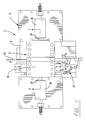
- Figure 1 is a top plan view of a machine module.
- Figure 2 is a sectional side view looking in the direction of the arrows 2-2 of Figure 1 showing the first and second ram assemblies of the tooling assembly, this view showing the positions of the parts when the ram assemblies are in their open or spaced apart positions;
- Figure 2 and Figures 3-5 are taken along an irregular vertical section line in order to show features which would not be shown if the section line were straight.
- Figure 3 is a view on an enlarged scale showing the positions of the parts at an intermediate stage of the cycle after the ram assemblies have moved partially towards each other.
- Figure 4 is a view similar to Figure 3 showing the positions of the parts when the ram assemblies are in their closed positions and substantially against each other.
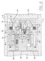
- Figure 5 is a view on an enlarged scale showing the leading end portion of the first ram assembly.
- Figure 6 is an enlarged view showing the leading end portion of the second ram assembly.
- Figures 7 and 8 show the first tooling assembly and portions of the ram assembly with the parts in exploded positions relative to each other, these views being intended to be placed beside each other along the lines A-A to show all of the parts of the assembly.
- Figure 9 is a timing diagram which illustrates the movement of the parts during an operating cycle.
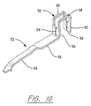
- Figure 10 is a perspective view of a contact terminal produced by the tooling assemblies shown in Figures 1-8.
- Figure 11 is a plan view of a portion of blanked strip which is formed by the tooling assembly shown in Figures 1-8.
- FIG. 1 shows a machine module 2 of the type described in U.S.-A-4,497,196 and US-A-4,819,476.
- the present invention is concerned with the tooling contained in the module and the module will, therefore, be described only briefly and to the extent necessary for an understanding of the invention.
- the module 2 comprises a module housing 4 having an upper surface 6 on which a ram housing 8 is supported.
- the ram housing comprises upper and lower ram housing plates 10, 12 and side plates 14, one of which is shown in Figure 2.
- the upper and lower housing plates and the side plates 14 define a rectangular passageway 16 in which there are first and second ram assemblies 18, 20.
- the side plates have aligned slots 22 through which strip material 70 is fed by a strip feeding mechanism 24 of the type described in U.S.-A-4,887,452.
- the ram assemblies 18, 20 are reciprocated towards and away from each other between open and closed positions by oscillating levers, the upper ends of which are shown at 26. These levers are coupled to the ram assemblies by couplings 28 as described in U.S. Patent 4,819,476.
- the first ram assembly 18 comprises a ram block 30, a spacer plate or backup plate 32, a tool holder 34, an additional tool holder 36, and a stripper plate 38.
- the backup plate 32, and the tool holders 34, 36 are secured to the face of the ram block 30.
- the stripper plate 38 is, when the parts are in the positions of Figure 2, spaced from the tool holder plate 36 and is resiliently biased to the position shown in Figure 2 by a biasing rod described in U.S.-A-4,819,476.
- the stripper plate 38 is moved relatively rightwardly as viewed in Figures 2-4 so that it is adjacent to the surface of the tool holder plate 36.
- the strip 70 is clamped between the opposed surfaces 39, 49 of the ram assemblies when they are in their closed positions.
- the second ram assembly 20 comprises a ram block 42, a backup or spacer plate 44, and tool holder plates 46, 48.
- the backup plate, and the tool holder plates are secured to the face of the ram block 42.
- the tool holder plate 48 has a facial surface 49 which is opposed to the facial surface 39 of the stripper plate 38.
- the first ram assembly has a first forming tooling assembly 40 therein and the second ram assembly has a second forming tooling assembly 50 therein.
- the tooling assemblies 40, 50 perform a U-ing operation on flat blanks 52a shown in Figure 11 which, after the U-ing operation, are further formed to produce contact terminals 52 as shown in Figure 10.
- Each terminal comprises a forward contact portion 54, an intermediate relatively flat portion 56, and a U-shaped wire contacting portion 58.
- the wire contacting portion comprises two spaced apart plate sections 60, 62 which are connected by parallel strap members 68.
- the plate sections 60, 62 have aligned slots 64, 66 which receive an insulated wire so that the opposed edges of the slot establish contact with the conducting core of the wire.
- Contact terminals 52 are manufactured by performing a series of stamping and forming operations on the strip material 70 which is fed through two or more modules of the type shown in Figure 1.
- a first module the strip material 70 is blanked; that is, the flat blanks 52a for the finished terminals are produced.
- the present invention is concerned only with the U-ing operation in which the portions 58a are U-ed to produce the wire receiving portions 58 of the terminals.
- the progression 72 as received in the module 2 comprises a central carrier strip 74 having side edges 76, 76'. Spaced apart pilot holes 78, 78' are provided for feeding the strip material through the module.
- the progression 72 has flat blanks 52a extending from both of the side edges 76, 76' and the tooling assemblies simultaneously U blanks on each side of the strip.
- the die assembly described herein is thus referred to as a "two-out" die assembly. It is, in addition, a multiple feed die assembly which is to say that four or more flat blanks are fed and formed during each operating cycle of the machine.
- first forming tools 80, 80' which are on the first ram assembly 18, second forming tools 82, 82', and fixed anvils 84, 84'.
- the second forming tools 82, 82' and the fixed anvils are on the second ram assembly 20. It will be apparent from Figures 5 and 6 that the tooling in the upper portion of the ram assemblies is a mirror image of the tooling assemblies in the lower portion. The corresponding tooling members and parts thereof are therefore identified by the same reference numerals differentiated by prime marks.
- Figures 2-5 are taken along an irregular vertical section line in order to show features which would not be shown if the section line were straight.
- Figures 2-5 show in the lower portion of the first ram assembly 18 the camming pin 138' which is described below and which is associated with toggle mechanism 108' but do not show camming pin 138 which is associated with the upper toggle 108.
- These figures show the toggle straightening spring 150 for the upper toggle 108 but do not show the corresponding spring 150' for the lower toggle 108'.
- Figures 7 and 8 show all of the elements in the forward portion of the first ram assembly and can be referred to along with Figures 2-5.
- the first forming tool 80 comprises a base portion 86 having a flange 88 extending therefrom which constitutes the tooling member.
- This flange or arm 88 has a free end 90 having a recess 91 on its lower surface.
- the free end is located at the facial surface 39 of the stripper block 38 and moves outwardly from the surface as will be described below, when the U-ing operation is carried out.
- the second forming tool 82 has a base portion 92 which is slidably contained in the tooling block 46 and which has a forwardly extending arm 94 having a free end 96.
- This arm constitutes the second forming member.
- the anvil 84 has a surface 98 which is located at the surface 49 of the tooling plate 48 but which is inclined slightly inwardly and downwardly so that the blank will be somewhat overformed or overbent in order to allow for spring back.
- a recess 100 is provided in the anvil 84 and has an inner end 102 and a side surface 101. The arm 94 moves past the recess, as shown in Figure 4 when the ram assemblies move to their closed positions.
- the toggle mechanism 108 which controls the movement of the first forming tool comprises first and second toggle links 110, 112 which are pivoted to each other at a knee joint 114.
- the first toggle link 110 is generally U-shaped as shown in Figure 7 having a bight or body portion 116 and spaced apart arms 118 extending from the body portion.
- the pivot pin 129 for the knee joint 114 extends between these arms and through the second toggle link 112.
- the inner fixed end of the first toggle link is pivoted on a pin 128 in an H-shaped adapter plate or mounting plate 122. This plate 122 is in turn received in an opening 124 in the tooling plate 34.
- the first toggle link 110 is pivoted in a recess 126 at the upper end of plate 122 by means of the pivot pin 128.
- the second link is pivoted on the pin 130 which extends through a recess 132 in the base portion 86 of the forming tool 80.
- the toggle mechanism is shifted from its straightened condition, Figure 2, to its broken condition, Figure 4, by means of a cam follower 134 which is mounted on the pivot pin 129.
- This cam follower is engaged by the chamfered end 136 of a camming pin 138 which is received in an opening 140 in a plate 142 which in turn is fixed in an opening 143 in the stripper plate 38.
- the opening 140 is counter-bored as shown at 144 and a reduced end portion of the pin 138 extends into the counter-bore and beyond an intermediate collar on the pin.
- a spring 146 surrounds the reduced end portion of the pin and bears against a face plate 148 which is secured to the plate 142 and which has a surface which is coplanar with the surface 39 of the stripper plate.
- a set screw 147 in plate 148 is in alignment with pin 138 and provides a fixed stop for the pin.
- each toggle mechanism is accomplished by means of a return springs 150 which are interposed between a depending lip 152 on the forming tool 80 and the leftwardly facing surface 154 as viewed in the drawing, of the H-shaped plate 122.
- the springs surround associated rods 156 which are mounted in the face plate 148 and which extend through the depending lip 156 of the forming tool 80. These rods 156 extend beyond the surface 154 of the plate 122 and into a recess in the tooling plate 34.
- the U-ing operation is only one of three operations carried out by the module shown in Figures 7 and 8. Additional openings as shown at 158, 160, 162, 164, 166, and 168 are provided in the tooling plates 34, 36 and in the stripper plate 38 for these other tooling members. These other tooling members are not shown or described for the reason that they are not part of the present invention. It might be mentioned, however, that the tooling which is received in the openings 158, 160 and 162 perform a qualifying operation on the U-shaped portions of the terminals and the tooling mounted in the openings 164, 166, and 168 perform forming operations on the contact end portions of the terminals.
- the base portion 92 of the second tooling member 50 has an opening 170 extending leftwardly therein from a location beneath the arm 94.
- a spring 172 is contained in this opening and is between a spacer plate 174 in the inner end of the opening thereby to bias the tooling member 50 leftwardly as viewed in Figure 6.
- the left-hand end 176 of the shank or base portion 92 is pivotally connected as at 178 to an upwardly extending lever 180 which is pivoted intermediate its ends at 182. The lever and the end portion of the shank 92 are received in a recess 184 in the tool holder plate 46.
- lever 180 has a set screw 188 therein which bears against the enlarged head 192 of a rod 194 which is slidably received in an opening 196 which extends through the tooling plates 46, 48 and to the facial surface 49.
- the end 198 of the rod 194 is adjacent to the facial surface 49.
- the rod 194 is moved leftwardly thereby causing the lever 180 to swing in a counter-clockwise direction and drive the tooling member 50 rightwardly as viewed in Figure 6.
- Such rightward movement of the projecting portion 94 bends the plate section 62 of the blank so that at the end of the stroke of the ram assemblies toward each other, the now- formed contact portion 58 of the terminal 52 is confined between the side surface of the tooling member 94 and the side surface 101 of anvil 84 with the end portion 90 of the first tooling member positioned in the U-shaped section and between the plate members 60,62.
- the rod 194 is moved leftwardly during the final portion of the stroke of the ram assemblies toward each other by a rod 200 which is slidably mounted in the stripper plate 38 and which has an enlarged end 204 which bears against the surface 106 of the tool holder plate 36.
- a spring 202 surrounds the rod 200 and is interposed between the enlarged end portion 204 and the inner end of a counter-bore as shown in Figures 2 and 6.
- An advantageous feature of the invention is that the use of heavy duty springs, such as would be required for the forming tool 80 if it were controlled by a spring, is avoided and the forming tool is controlled by a toggle mechanism.
- Springs are used in the disclosed embodiment as shown at 202, 146, 150, and 172 but these are light duty return springs. They are long-lived and do not significantly increase the capacity of the press required for the punch and die assembly.
- Figure 9 describes the positions of the principle parts of the tooling assemblies during a complete operating cycle in which the ram assemblies move from their open positions, Figure 2, to their closed positions shown in Figure 4 and back to their open positions. It will be apparent from Figure 9 that the actual forming operations take place only during the final portion of the stroke of the ram assemblies to their closed positions.
- the travel of the rams is relatively short as compared with conventional stamping and forming dies and as shown in Figure 9, the total travel of each ram is 10.2 mm in the disclosed embodiment.
- the ram assemblies will be in the positions of Figure 2 and the strip material 70 will have been fed so that a plurality of flat blanks 52a, 52a' will be positioned between the tooling assemblies 40, 50, 40', 50' in the ram assemblies 18, 20.
- the stripper plate 38 is in its extended position of Figure 2.
- the facial surface 39 of the stripper plate 38 moves against the surface 49 of the tooling plate 48 on the second ram assembly 20 and the strip material is deflected a short distance rightwardly as viewed in the drawing.
- the tooling plates 34, 36 move relatively towards the rearwardly facing surface 104 of the stripper plate until the surfaces 104, 106 are against each other.
- the ends 90, 90' of the forming tools 80, 80' begin to move beyond the facial surface 39 of the stripper plate and form the wire receiving portions 58, 58' of the blanks.
- the toggle mechanisms remain in their straightened condition; however, toward the end of the cycle, the toggles are shifted to their broken conditions by the camming pins 138, 138'.
- the second tooling members 80, 80' move from the positions of Figure 4 to the positions of Figure 5 thereby to complete the forming operation.
- the toggle mechanisms are straightened by the compression springs 150 and the parts return to their positions as shown in Figure 2.
- the practice of the invention does not require the stripper plate 38; the stripper plate is required in the disclosed embodiment to remove the formed terminal strip from the forming tools on the first ram assembly. Under some circumstances, the invention might be used in a die assembly which does not require a stripper plate. Also, it should be noted that the timing diagram, Figure 9, is valid for a particular embodiment of the invention. Alternative embodiments might be designed such that the operations described take place at times in the cycle other than those indicated in the diagram.
Landscapes
- Engineering & Computer Science (AREA)
- Mechanical Engineering (AREA)
- Manufacturing & Machinery (AREA)
- Press Drives And Press Lines (AREA)
- Manufacturing Of Electrical Connectors (AREA)
Claims (3)
- Stanz- und Formmaschine (2) mit einem ersten und einem zweiten Maschinenteil (18, 20), die sich während jedes Betriebszyklus der Maschine zwischen einer geöffneten und einer geschlossenen Position relativ aufeinander zu und voneinander weg bewegen,a) wobei der erste und der zweite Maschinenteil (18, 20) einen ersten und einen zweiten vorderen Endbereich (39, 49) aufweisen, die einander gegenüberliegend angeordnet sind und die aneinander anliegen, wenn sich die Maschinenteile (18, 20) in ihrer geschlossenen Position befinden, und die voneinander beabstandet sind, wenn sich die Maschinenteile (18, 20) in der geöffneten Position befinden,b) wobei der erste Teil (18) folgendes aufweist:- eine erste hin- und hergewegbare Ramme (30) und eine Abstreifplatte (38), wobei der erste vordere Endbereich (39) die Abstreifplatte (38) aufweist sowie die erste Ramme (30) teilweise aufweist,- ein darin befindliches Maschinenelement (40, 80), das sich senkrecht zu dem vorderen Endbereich (39) erstreckt, wenn sich die Maschinenteile (18, 20) in ihrer geschlossenen Position befinden, und das an einem Werkstück (70) angreift, das sich während der Bewegung der Teile (18, 20) von ihrer geöffneten Position in ihre geschlossene Position zwischen den vorderen Endbereichen befindet, wobei sich das Element (40, 80) während eines Teils des Betriebszyklus in einer ausgefahrenen Position befindet, in der es in das zweite Maschinenteil (20) augefahren ist, und wobei sich das Element (40, 80) während eines anderen Teils des Betriebszyklus in einer zurückgezogenen Position befindet, in der es von dem zweiten Maschinenteil (20) zurückbewegt ist, und- eine Elementbewegungseinrichtung zum Bewegen des Elements (40, 80) zwischen seiner ausgefahrenen und seiner zurückgezogenen Position, wobei die Elementbewegungseinrichtung eine Kniehebeleinrichtung (108) in dem ersten Maschinenteil (18) aufweist und die Kniehebeleinrichtung ein erstes und ein zweites Gelenkglied (110, 112) aufweist, die an einem Kniegelenk (114) schwenkbar miteinander verbunden sind, wobei das erste Gelenkglied (110) mit dem ersten Maschinenteil (18) schwenkbar verbunden ist und das Maschinenelement (40, 80) mit dem zweiten Gelenkglied (112) schwenkbar verbunden ist, wobei sich die Gelenkglieder in ihrem miteinander ausgerichteten und gerade ausgerichteten Zustand befinden, wenn das Element (40, 80) in seiner ausgefahrenen Position ist, und sich in ihrem geknickten Zustand befinden, wenn das Element (40, 80) in seiner zurückbewegten Position ist, und wobei eine Kniehebel-Steuereinrichtung (134, 138, 150, 156) zum Geradeausrichten und Knicken der Kniehebeleinrichtung vorgesehen ist,c) wobei das erste Gelenkglied (110) an der ersten Ramme (30) angelenkt ist,d) wobei sich die Kniehebeleinrichtung (108) während eines Anfangsteils des Zyklus, während dessen sich die Maschinenteile (18, 20) relativ aufeinander zu bewegen und während dessen sich die Abstreifplatte (38) relativ auf die erste Ramme (30) zubewegt, in ihrem gerade ausgerichteten Zustand befindet,e) wobei die Kniehebeleinrichtung (108) während eines auf den Anfangsteil folgenden mittleren Teils des Zyklus in ihren geknickten Zustand verlagert wird,f) wobei die Kniehebel-Steuereinrichtung eine Kniehebel-Knickeinrichtung (134, 136, 138) und eine Kniehebel-Geraderichteinrichtung (150, 156) aufweist, die in dem ersten Maschinenteil (18) enthalten sind,g) wobei die Kniehebel-Geraderichteinrichtung eine federnd nachgiebige Einrichtung (150) aufweist, die die Kniehebeleinrichtung (108) in ihren gerade ausgerichteten Zustand vorspannt,h) wobei die Kniehebel-Knickeinrichtung ein Steuerflächenfolgerglied (134) und ein Steuerflächenglied (136, 138) aufweist, das am Ende des Anfangsteils des Zyklus an dem Steuerflächenfolgerglied (134) angreift, um die Kniehebeleinrichtung (108) in ihren geknickten Zustand zu verschieben,dadurch gekennzeichnet,i) daß das Steuerflächenfolgerglied (134) an dem Kniegelenk (114) der Kniehebeleinrichtung (108) angeordnet ist, undj) daß das Steuerflächenglied (136, 138) in der Abstreifplatte (38) enthalten ist.
- Maschine nach Anspruch 1,
dadurch gekennzeichnet,
daß das Maschinenelement (40, 80) einen integralen Basisbereich (86) aufweist, der an dem zweiten Gelenkglied (112) schwenkbar angebracht ist, daß der Basisbereich eine Schulter aufweist, die der ersten Ramme (30) gegenüberliegt, daß die Kniehebel-Geraderichteinrichtung eine Feder (150) aufweist, die zwischen der ersten Ramme (30) und der Schulter angeordnet ist, so daß die Feder (150) zusammengedrückt wird, wenn das Steuerflächenglied (136, 138) an dem Steuerflächenfolgerglied (134) angreift und die Kniehebeleinrichtung (108) in ihren geknickten Zustand verlagert wird, und daß während der Bewegung der Maschinenteile (18, 20) von ihrer geschlossenen Position in ihre geöffnete Position die zusammengedrückte Feder (150) die Kniehebeleinrichtung (108) in ihren gerade ausgerichteten Zustand zurückführt. - Maschine nach einem der Ansprüche 1 oder 2,
dadurch gekennzeichnet,
daß der zweite Maschinenteil (20) eine zweite Ramme (42) aufweist, die in Richtung auf die erste Ramme (30) zu und von dieser weg hin- und herbewegbar ist, daß es sich bei dem Maschinenelement (40) um ein erstes Formwerkzeug (80) handelt, daß an der zweiten Ramme (42) ein zweites Formwerkzeug (94) vorgesehen ist, und daß es sich bei dem Werkstück (70) um einen anfangs flachen Zuschnitt handelt, der durch das erste und das zweite Formwerkzeug (80, 94) in eine U-förmige Gestalt geformt wird.
Applications Claiming Priority (2)
| Application Number | Priority Date | Filing Date | Title |
|---|---|---|---|
| US07/598,289 US5070719A (en) | 1990-10-16 | 1990-10-16 | Tooling control mechanisms for stamping and forming die assemblies |
| US598289 | 1990-10-16 |
Publications (3)
| Publication Number | Publication Date |
|---|---|
| EP0481426A2 EP0481426A2 (de) | 1992-04-22 |
| EP0481426A3 EP0481426A3 (en) | 1992-10-07 |
| EP0481426B1 true EP0481426B1 (de) | 1995-04-05 |
Family
ID=24394982
Family Applications (1)
| Application Number | Title | Priority Date | Filing Date |
|---|---|---|---|
| EP91117576A Expired - Lifetime EP0481426B1 (de) | 1990-10-16 | 1991-10-15 | Presswerkzeugkontrollmechanismen für Form-Presswerkzeuge |
Country Status (6)
| Country | Link |
|---|---|
| US (1) | US5070719A (de) |
| EP (1) | EP0481426B1 (de) |
| JP (1) | JPH04274184A (de) |
| BR (1) | BR9104421A (de) |
| DE (1) | DE69108667T2 (de) |
| MX (1) | MX9101485A (de) |
Families Citing this family (2)
| Publication number | Priority date | Publication date | Assignee | Title |
|---|---|---|---|---|
| IT1278355B1 (it) * | 1995-02-06 | 1997-11-20 | Sapim Amada Spa | Attrezzatura piegatrice per lamiere. |
| CN111185529B (zh) * | 2020-01-16 | 2021-05-28 | 马鞍山市华能电力线路器材有限责任公司 | 一种热镀锌楔形线夹快速成型模具 |
Family Cites Families (10)
| Publication number | Priority date | Publication date | Assignee | Title |
|---|---|---|---|---|
| US1550580A (en) * | 1924-12-06 | 1925-08-18 | Marquette Tool & Mfg Co | Blank-holding means |
| CH354331A (fr) * | 1959-05-05 | 1961-05-15 | Bobst Fils Sa J | Mécanisme d'entraînement de la platine mobile d'une presse à platines |
| US3661008A (en) * | 1970-03-17 | 1972-05-09 | Wickman Mach Tool Sales Ltd | Presses |
| SU722636A1 (ru) * | 1978-04-10 | 1980-03-25 | Предприятие П/Я А-3238 | Штамп дл гибки штучных заготовок |
| US4497196A (en) * | 1983-02-07 | 1985-02-05 | Amp Incorporated | Apparatus for performing operations on strip material |
| SU1247125A1 (ru) * | 1984-12-25 | 1986-07-30 | Тамбовский Завод Подшипников Скольжения | Гибочный пуансон |
| WO1988005724A1 (en) * | 1987-02-03 | 1988-08-11 | Bruderer Ag | Press drive |
| US4819476A (en) * | 1987-07-17 | 1989-04-11 | Amp Incorporated | Tooling for forming machines having improved guidance, tool mounting, and pilot pin systems |
| DE3825128A1 (de) * | 1988-07-23 | 1990-01-25 | Hilgeland Gmbh & Co Geb | Stauchpresse zum stauchen von drahtabschnitten vorbestimmter laenge zu kugeln und dgl. |
| US4934173A (en) * | 1989-03-17 | 1990-06-19 | Amp Incorporated | Stamping and forming machine having toggles for reciprocating the tooling assemblies |
-
1990
- 1990-10-16 US US07/598,289 patent/US5070719A/en not_active Expired - Lifetime
-
1991
- 1991-10-09 MX MX9101485A patent/MX9101485A/es unknown
- 1991-10-11 BR BR919104421A patent/BR9104421A/pt not_active IP Right Cessation
- 1991-10-15 EP EP91117576A patent/EP0481426B1/de not_active Expired - Lifetime
- 1991-10-15 DE DE69108667T patent/DE69108667T2/de not_active Expired - Fee Related
- 1991-10-16 JP JP3296300A patent/JPH04274184A/ja active Pending
Also Published As
| Publication number | Publication date |
|---|---|
| DE69108667D1 (de) | 1995-05-11 |
| MX9101485A (es) | 1992-06-05 |
| EP0481426A2 (de) | 1992-04-22 |
| DE69108667T2 (de) | 1995-08-17 |
| JPH04274184A (ja) | 1992-09-30 |
| EP0481426A3 (en) | 1992-10-07 |
| US5070719A (en) | 1991-12-10 |
| BR9104421A (pt) | 1992-06-09 |
Similar Documents
| Publication | Publication Date | Title |
|---|---|---|
| US4510789A (en) | Press brake | |
| EP0329724B1 (de) | Werkzeuge für formeinrichtungen mit verbesserten führungs-, werkzeugaufstellungs- und führungszapfenanordnungen | |
| EP0481426B1 (de) | Presswerkzeugkontrollmechanismen für Form-Presswerkzeuge | |
| EP0657973B1 (de) | Anbringungsvorrichtung für elektrische Anschlüsse mit verbessertem, gespaltenen Zyklus | |
| EP0338803B1 (de) | Stanz- und Umformmaschine mit verbesserten Suchsliften | |
| JP2002018536A (ja) | 複合プレス加工装置 | |
| CN213944542U (zh) | 一种银点触头成型模具 | |
| US5271256A (en) | Tooling module for stamping and forming machine | |
| CN211727186U (zh) | 一种用以成型开关端子的冲压成型机构 | |
| US5884520A (en) | Die set having shut height adjust and stripper plate actuator mechanisms | |
| US4483170A (en) | Press machine structure | |
| SU1595611A1 (ru) | Последовательный штамп дл изготовлени лепестков контактов электрических разъемов | |
| JPH0719617Y2 (ja) | プレス型のカム装置 | |
| CN116557391B (zh) | 一种卡扣及冲压设备 | |
| CN217474665U (zh) | 送料机构及碟形弹簧回收处理设备 | |
| CN219648493U (zh) | 一种锻压生产线体上切飞边工作站 | |
| SU1248085A1 (ru) | Штамп дл гибки и отрезки выводов радиоэлементов | |
| SU1556793A1 (ru) | Штамп дл вырубки | |
| SU1127670A1 (ru) | Штамп дл обработки листового материала | |
| SU1143531A1 (ru) | Прижимное устройство | |
| SU1655596A1 (ru) | Гибочный узел многоползункового гибочного автомата | |
| SU413059A1 (de) | ||
| JP3607192B2 (ja) | プレス加工装置 | |
| SU927389A1 (ru) | Устройство дл изготовлени из металлической полосы декоративных цепочек | |
| SU1315081A1 (ru) | Устройство дл направлени листового материала |
Legal Events
| Date | Code | Title | Description |
|---|---|---|---|
| PUAI | Public reference made under article 153(3) epc to a published international application that has entered the european phase |
Free format text: ORIGINAL CODE: 0009012 |
|
| AK | Designated contracting states |
Kind code of ref document: A2 Designated state(s): DE FR GB IT NL |
|
| PUAL | Search report despatched |
Free format text: ORIGINAL CODE: 0009013 |
|
| AK | Designated contracting states |
Kind code of ref document: A3 Designated state(s): DE FR GB IT NL |
|
| RAP1 | Party data changed (applicant data changed or rights of an application transferred) |
Owner name: THE WHITAKER CORPORATION |
|
| 17P | Request for examination filed |
Effective date: 19930406 |
|
| 17Q | First examination report despatched |
Effective date: 19930604 |
|
| GRAA | (expected) grant |
Free format text: ORIGINAL CODE: 0009210 |
|
| AK | Designated contracting states |
Kind code of ref document: B1 Designated state(s): DE FR GB IT NL |
|
| REF | Corresponds to: |
Ref document number: 69108667 Country of ref document: DE Date of ref document: 19950511 |
|
| ITF | It: translation for a ep patent filed |
Owner name: GUZZI E RAVIZZA S.R.L. |
|
| ET | Fr: translation filed | ||
| PLBE | No opposition filed within time limit |
Free format text: ORIGINAL CODE: 0009261 |
|
| STAA | Information on the status of an ep patent application or granted ep patent |
Free format text: STATUS: NO OPPOSITION FILED WITHIN TIME LIMIT |
|
| 26N | No opposition filed | ||
| PGFP | Annual fee paid to national office [announced via postgrant information from national office to epo] |
Ref country code: NL Payment date: 19980914 Year of fee payment: 8 |
|
| PG25 | Lapsed in a contracting state [announced via postgrant information from national office to epo] |
Ref country code: NL Free format text: LAPSE BECAUSE OF NON-PAYMENT OF DUE FEES Effective date: 20000501 |
|
| NLV4 | Nl: lapsed or anulled due to non-payment of the annual fee |
Effective date: 20000501 |
|
| REG | Reference to a national code |
Ref country code: GB Ref legal event code: IF02 |
|
| PGFP | Annual fee paid to national office [announced via postgrant information from national office to epo] |
Ref country code: GB Payment date: 20040915 Year of fee payment: 14 |
|
| PGFP | Annual fee paid to national office [announced via postgrant information from national office to epo] |
Ref country code: FR Payment date: 20041004 Year of fee payment: 14 |
|
| PGFP | Annual fee paid to national office [announced via postgrant information from national office to epo] |
Ref country code: DE Payment date: 20041029 Year of fee payment: 14 |
|
| PG25 | Lapsed in a contracting state [announced via postgrant information from national office to epo] |
Ref country code: IT Free format text: LAPSE BECAUSE OF NON-PAYMENT OF DUE FEES;WARNING: LAPSES OF ITALIAN PATENTS WITH EFFECTIVE DATE BEFORE 2007 MAY HAVE OCCURRED AT ANY TIME BEFORE 2007. THE CORRECT EFFECTIVE DATE MAY BE DIFFERENT FROM THE ONE RECORDED. Effective date: 20051015 Ref country code: GB Free format text: LAPSE BECAUSE OF NON-PAYMENT OF DUE FEES Effective date: 20051015 |
|
| PG25 | Lapsed in a contracting state [announced via postgrant information from national office to epo] |
Ref country code: DE Free format text: LAPSE BECAUSE OF NON-PAYMENT OF DUE FEES Effective date: 20060503 |
|
| GBPC | Gb: european patent ceased through non-payment of renewal fee |
Effective date: 20051015 |
|
| PG25 | Lapsed in a contracting state [announced via postgrant information from national office to epo] |
Ref country code: FR Free format text: LAPSE BECAUSE OF NON-PAYMENT OF DUE FEES Effective date: 20060630 |
|
| REG | Reference to a national code |
Ref country code: FR Ref legal event code: ST Effective date: 20060630 |