EP0481244A1 - Warning light - Google Patents
Warning light Download PDFInfo
- Publication number
- EP0481244A1 EP0481244A1 EP91116101A EP91116101A EP0481244A1 EP 0481244 A1 EP0481244 A1 EP 0481244A1 EP 91116101 A EP91116101 A EP 91116101A EP 91116101 A EP91116101 A EP 91116101A EP 0481244 A1 EP0481244 A1 EP 0481244A1
- Authority
- EP
- European Patent Office
- Prior art keywords
- warning light
- light according
- reflector
- deflecting mirror
- bearing part
- Prior art date
- Legal status (The legal status is an assumption and is not a legal conclusion. Google has not performed a legal analysis and makes no representation as to the accuracy of the status listed.)
- Ceased
Links
Images

Classifications
-
- B—PERFORMING OPERATIONS; TRANSPORTING
- B60—VEHICLES IN GENERAL
- B60Q—ARRANGEMENT OF SIGNALLING OR LIGHTING DEVICES, THE MOUNTING OR SUPPORTING THEREOF OR CIRCUITS THEREFOR, FOR VEHICLES IN GENERAL
- B60Q1/00—Arrangement of optical signalling or lighting devices, the mounting or supporting thereof or circuits therefor
- B60Q1/26—Arrangement of optical signalling or lighting devices, the mounting or supporting thereof or circuits therefor the devices being primarily intended to indicate the vehicle, or parts thereof, or to give signals, to other traffic
- B60Q1/2611—Indicating devices mounted on the roof of the vehicle
-
- F—MECHANICAL ENGINEERING; LIGHTING; HEATING; WEAPONS; BLASTING
- F21—LIGHTING
- F21W—INDEXING SCHEME ASSOCIATED WITH SUBCLASSES F21K, F21L, F21S and F21V, RELATING TO USES OR APPLICATIONS OF LIGHTING DEVICES OR SYSTEMS
- F21W2111/00—Use or application of lighting devices or systems for signalling, marking or indicating, not provided for in codes F21W2102/00 – F21W2107/00
- F21W2111/06—Use or application of lighting devices or systems for signalling, marking or indicating, not provided for in codes F21W2102/00 – F21W2107/00 for aircraft runways or the like
Definitions
- the invention relates to a warning light according to the type of the main claim, as described for example in DE-GM 84 27 524.3.
- a fixed lamp is immersed from below through a recess in a reflector, which generates a horizontal light beam.
- This reflector is driven by a motor, so that the light beam is rotated by the reflector in a horizontal plane, as is known, for example, in police vehicles, fire engines, technical assistance vehicles, etc.
- a disadvantage of the known luminaire is the relatively large recess in the reflector in order to insert the lamp from below, ie perpendicular to the direction of radiation.
- there is no point light source but the filament extends over a certain area transverse to the direction of the radiation. This leads to a non-ideal light distribution in the light beam.
- the deflecting mirror and the support element can be formed in one piece and / or the deflecting mirror and the bearing part can also be formed in one piece.
- the deflecting mirror can of course also be designed such that it can be plugged onto the bearing part.
- Plastic is particularly suitable as the material.
- the deflecting mirror 24 is fastened at an angle of 45 to the axis of rotation of the bearing part 20 on the holding area 23 by means of a pipe-shaped holding area 25 at the lower end of the deflecting mirror 24.
- the deflecting mirror 24 or the tubular arch-like holding area 25 can be glued, screwed or connected via a plug connection. It is also possible to form the deflecting mirror 24 and the bearing part 20 in one piece, for example as a plastic injection-molded part.
- the remaining part of the warning lamp can be designed in accordance with the first exemplary embodiment, i.e. the bearing part 20 provided with the deflection mirror 31 is inserted and latched in the base 11 shown and described there according to the first exemplary embodiment.
Landscapes
- Engineering & Computer Science (AREA)
- Mechanical Engineering (AREA)
- Non-Portable Lighting Devices Or Systems Thereof (AREA)
Abstract
Description
Die Erfindung betrifft eine Warnleuchte nach der Gattung des Hauptanspruches, wie sie beispielsweise in der DE-GM 84 27 524.3 beschrieben ist. Bei der bekannten Warnleuchte taucht eine ortsfest fixierte Lampe von unten her durch eine Ausnehmung in einen Reflektor ein, der ein horizontales Lichtbündel erzeugt. Dieser Reflektor ist motorisch angetrieben, so daß das Lichtbündel durch den Reflektor in einer horizontalen Ebene gedreht wird, wie dies beispielsweise bei Polizeifahrzeugen, Feuerwehrfahrzeugen, Fahrzeugen des technischen Hilfsdienstes usw. bekannt ist. Nachteilig an der bekannten Leuchte ist die relativ große Ausnehmung im Reflektor, um die Lampe von unten her, also senkrecht zur Abstrahlrichtung einzuführen. Darüberhinaus liegt bei Verwendung üblicher Glühbirnen keine punktförmige Lichtquelle vor, sondern die Wendel erstreckt sich über einen gewissen Bereich quer zur Abstahlrichtung. Dies führt zu einer nicht idealen Lichtverteilung im Lichtbündel.The invention relates to a warning light according to the type of the main claim, as described for example in DE-GM 84 27 524.3. In the known warning lamp, a fixed lamp is immersed from below through a recess in a reflector, which generates a horizontal light beam. This reflector is driven by a motor, so that the light beam is rotated by the reflector in a horizontal plane, as is known, for example, in police vehicles, fire engines, technical assistance vehicles, etc. A disadvantage of the known luminaire is the relatively large recess in the reflector in order to insert the lamp from below, ie perpendicular to the direction of radiation. In addition, when using conventional light bulbs, there is no point light source, but the filament extends over a certain area transverse to the direction of the radiation. This leads to a non-ideal light distribution in the light beam.
Weiterhin ist eine Warnleuchte bekannt, bei der die Lampe fest im Reflektor angeordnet ist und zusammen mit diesem rotiert, um die vorstehend beschriebene Rotation des Lichtbündels um eine vertikale Achse zu erzielen. Bei dieser Anordnung ist infolge der größeren Masse des rotierenden Bereichs nicht nur eine aufwendigere und teurere Antriebs- und Lagervorrichtung erforderlich, sondern zur Stromzuführung der Lampe müssen auch Schleifkontakte vorgesehen sein, die ebenfalls teuer und aufwendig in der Herstellung sind. Darüberhinaus kann es durch Oberflächenkorrosion auf den Schleifkontakten zu Lampenausfällen kommen, so daß eine geringere Zuverlässigkeit zu befürchten ist.Furthermore, a warning lamp is known in which the lamp is arranged fixedly in the reflector and rotates together with it in order to achieve the rotation of the light bundle described above about a vertical axis. With this arrangement, due to the greater mass of the rotating area, not only is a more complex and expensive drive and bearing device required, but also sliding contacts must be provided for the power supply of the lamp, which are also expensive and complex to manufacture. In addition, surface corrosion on the sliding contacts can lead to lamp failures, so that lower reliability is to be feared.
Die erfindungsgemäße Warnleuchte mit den kennzeichnenden Merkmalen des Hauptanspruches hat den Vorteil, daß die Lampe wie beim an zweiter Stelle genannten Stand der Technik fest im Reflektor zentral angeordnet ist, wobei die Glühwendel in Abstrahlrichtung ausgerichtet ist. Obwohl die Lampe daher eine optimale Anordnung im Reflektor aufweist, können Schleifkontakte vollständig entfallen, und es sind auch keine seitlichen Ausnehmungen im Reflektor erforderlich, wie dies beim zuerst genannten Stand der Technik der Fall ist. Da nur ein relativ leichter Umlenkspiegel rotiert, kann dessen Lager- und Antriebsmechanismus einfach und kostengünstig ausgebildet werden. Insgesamt wird daher bei guter Lichtabstrahlung eine gegenüber dem Stand der Technik einfachere und kostengünstigere Konstruktion möglich.The warning light according to the invention with the characterizing features of the main claim has the advantage that the lamp, as in the prior art mentioned in the second place, is arranged centrally in the reflector, the filament being oriented in the direction of radiation. Although the lamp therefore has an optimal arrangement in the reflector, sliding contacts can be dispensed with entirely, and no lateral recesses in the reflector are required, as is the case with the first-mentioned prior art. Since only a relatively light deflecting mirror rotates, its bearing and drive mechanism can be designed simply and inexpensively. Overall, therefore, with good light radiation, a simpler and less expensive construction is possible compared to the prior art.
Durch die in den Unteransprüchen aufgeführten Maßnahmen sind vorteilhafte Weiterbildungen und Verbesserungen der im Hauptanspruch angegebenen Warnleuchte möglich. Im einfachsten Falle ist der Umlenkspiegel als Planspiegel ausgebildet, der im wesentlichen um 45° zur Rotationsachse geneigt ist. Es ist jedoch auch möglich, daß der Umlenkspiegel eine den Öffnungwinkel des vom Reflektor abgestrahlten Lichtbündels verändernde, insbesondere verringernde Wölbung aufweist und insgesamt um im wesentlichen 45 zur Rotationsachse geneigt ist. Hierdurch kann die Tiefe des Reflektors zur Erzeugung einer geringeren Bauhöhe reduziert werden und das dann gegebenenfalls nicht ausreichend gebündelte Lichtbündel kann dann ergänzend durch den Umlenkspiegel gebündelt werden.Advantageous further developments and improvements of the warning light specified in the main claim are possible through the measures listed in the subclaims. In the simplest case, the deflecting mirror is designed as a plane mirror which is inclined essentially by 45 ° to the axis of rotation. However, it is also possible for the deflecting mirror to have a curvature which changes, in particular reducing, the opening angle of the light beam emitted by the reflector and is inclined overall by essentially 45 to the axis of rotation. As a result, the depth of the reflector can be reduced to produce a lower overall height, and the light bundle, which may then not be bundled sufficiently, can then additionally be bundled by the deflecting mirror.
Der Umlenkspiegel ist zweckmäßigerweise auf einem drehbar in einer Haltevorrichtung für den Reflektor gelagerten Lagerteil angebracht, das zur Lagerung insbesondere ein in die Haltevorrichtung eintauchendes Lagerrohrteil aufweisen kann, um eine einfache und stabile Lagerung zu erzielen.The deflecting mirror is expediently mounted on a bearing part which is rotatably mounted in a holding device for the reflector and which, for storage, can in particular have a bearing tube part immersed in the holding device in order to achieve simple and stable storage.
Zur Erzielung eines einfachen Aufbaus mit wenigen Teilen weist das Lagerteil einen Antriebszahnkranz auf, in den ein Antriebszahnrad des an der Haltevorrichtung fixierten Elektromotors eingreift.In order to achieve a simple construction with few parts, the bearing part has a drive sprocket into which a drive sprocket of the electric motor fixed on the holding device engages.
Um eine möglichst kompakte Bauweise zu gewährleisten, weist das Lagerteil zum Reflektor hin eine der Gestalt des Reflektors angepaßte kreiskegelartige Erweiterung zur berührungslosen Aufnahme des an der Haltevorrichtung fixierten Reflektors auf. Das Lagerteil dreht sich dadurch um den darin ortsfest fixierten Reflektor.In order to ensure a construction that is as compact as possible, the bearing part has a circular cone-like extension toward the reflector that is adapted to the shape of the reflector, for the contactless reception of the reflector fixed to the holding device. As a result, the bearing part rotates around the reflector fixed in place.
Zur Erhöhung der Stabilität und um Schwingungen zu vermeiden, ist der Umlenkspiegel durch ein Abstützelement am Lagerteil abgestützt. Dieses Abstützelement kann als wenigstens eine Abstütztstrebe ausgebildet sein oder der Umlenkspiegel ist an einem Stützrohr oder einer teilrohrartigen Stütze als Abstützelement nach Art einer Schrägschnittfläche angeordnet, wobei dieses Stützrohr bzw. diese teilrohrartige Stütze eine Austrittsöffnung für das Lichtbündel in radialer Richtung aufweist.To increase stability and to avoid vibrations, the deflecting mirror is supported by a support element on the bearing part. This support element can be designed as at least one support strut or the deflecting mirror is arranged on a support tube or a partial tube-like support as a support element in the manner of an oblique cut surface, this support tube or this partial tube-like support having an outlet opening for the light bundle in the radial direction.
Zur Vereinfachung der Konstruktion kann der Umlenkspiegel und das Abstützelement einstückig ausgebildet sein und/oder auch der Umlenkspiegel und das Lagerteil können einstückig ausgebildet sein. Alternativ hierzu kann der Umlenkspiegel selbstverständlich auch auf das Lagerteil aufsteckbar ausgebildet sein. Als Material eignet sich vor allem Kunststoff.To simplify the construction, the deflecting mirror and the support element can be formed in one piece and / or the deflecting mirror and the bearing part can also be formed in one piece. As an alternative to this, the deflecting mirror can of course also be designed such that it can be plugged onto the bearing part. Plastic is particularly suitable as the material.
Damit die Warnleuchte beispielsweise auch von Hubschraubern aus besser erkannt werden kann, weist der Umlenkspiegel Öffnungen oder Ausnehmungen für den Durchlaß eines Teils des Lichtbündels in Richtung der Rotationsachse auf, die im einsatzbereit montierten Zustand, beispielsweise auf einem Polizeifahrzeug, im wesentlichen vertikal verläuft. Alternativ hierzu ist es auch möglich, die Querschnittsfläche des Lichtbündels größer zu machen, als die Projektion des Umlenkspiegels auf diese Querschnittsfläche. Hierdurch kann ein Teil des Lichtbündels den Umlenkspiegel passieren, ohne umgelenkt zu werden.So that the warning light can also be better recognized from helicopters, for example, the deflecting mirror has openings or recesses for the passage of part of the Beam of light in the direction of the axis of rotation, which in the ready-to-use state, for example on a police vehicle, runs essentially vertically. Alternatively, it is also possible to make the cross-sectional area of the light beam larger than the projection of the deflecting mirror onto this cross-sectional area. As a result, part of the light beam can pass the deflecting mirror without being deflected.
Ausführungbeispiele der Erfindung sind in der Zeichnung dargestellt und in der nachfolgenden Beschreibung näher erläutert. Es zeigen:
- Figur 1 eine Schnittdarstellung eines ersten Ausführungsbeispiels einer Warnleuchte mit einem durch eine Abstützstrebe abgestützen Umlenkspiegel und
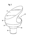
- Figur 2 eine perspektivische Darstellung eines Umlenkspiegels, der durch eine rohrförmige Abstützung am Lagerteil befestigt ist als Teildarstellung eines zweiten Ausführungsbeispiels.
- Figure 1 is a sectional view of a first embodiment of a warning lamp with a deflecting mirror supported by a support strut and
- Figure 2 is a perspective view of a deflecting mirror, which is attached by a tubular support to the bearing part as a partial representation of a second embodiment.
Bei dem in Figur 1 dargestellten ersten Ausführungsbeispiel ist ein topfförmiges, lichtdurchlässiges Gehäuse 10 auf einen Sockel 11 mittels einer Dichtung 12 dichtend aufgesteckt. Zur sicheren Befestigung können nicht dargestellte Schrauben, ein Bajonettverschluß, ein Schraubgewinde oder dergleichen dienen. Der Sockel 11 weist an seinem unteren Ende radial nach innen weisende Befestigungslaschen 13 auf, die zur Schraubbefestigung der Warnleuchte beispielsweise auf dem Fahrzeugdach eines Feuerwehrfahrzeuges, eines Polizeifahrzeuges oder des Fahrzeuges eines technischen Hilfsdienstes dienen. In Abhängigkeit der jeweiligen Anwendung ist das Gehäuse 10 meistens blau oder gelb eingefärbt.In the first exemplary embodiment shown in FIG. 1, a pot-shaped,
Im mittleren Bereich des Sockels 11, der als Haltevorrichtung für die übrigen Teile der Warnleuchte dient, kann durch eine kreiszylindrische Ausnehmung 14 von unten her eine Fassung 15 für eine Glühlampe 16 eingesetzt werden. Hierbei handelt es sich um eine in der Kraftfahrzeugtechnik übliche Fassung und übliche Glühlampe, so daß auf eine detailliertere Beschreibung verzichtet werden kann. Im eingesetzten und verrasteten Zustand befindet sich die Fassung 15 in der kreiszylindrischen Ausnehmung 14, und die Glühlampe 16 ragt oben aus dem Sockel 11 heraus und in einen im wesentlichen parabolischen Reflektor 17 hinein, dessen Reflektoröffnung nach oben weist. Zur Fixierung des Reflektors 17 am Sockel 11 weist der Sockel 11 Rastnasen 18 auf, die beim Aufsetzen des Reflektors 17 auf den Sockel 11 durch Öffnungen deselben hindurchgreifen und den Reflektor 17 dann federnd verrasten.In the central area of the
Ein rohrförmiger Lagerbereich 19 eines Lagerteils 20 greift von oben her in eine entsprechend rohrförmig ausgebildete Lagerausnehmung 21 des Sockels 11 ein und bewirkt eine drehbare Lagerung des Lagerteils 10 um eine vertikale Rotationsachse. Zur axialen Fixierung des Lagerteils 20, also zur Verhinderung eines Herausfallens oder Herausgleitens des Lagerteils 20 aus der Lagerausnehmung 21 weist der Sockel 11 Rastnasen 22 auf, die beim Einstecken des Lagerteils 20 in einen Absatz des rohrförmigen Lagerbereichs 19 einrasten. Je nach Bedarf können selbstverständlich nicht dargestellte Wälzlager oder zustätzliche Gleitlager vorgesehen sein.A tubular bearing
Vom oberen Ende des rohrförmigen Lagerbereichs 19 aus erweitert sich das Lagerteil 20 kreiskegelartig nach außen und mündet an einem kreisringförmigen Haltebereich 23 für einen Umlenkspiegel 24. Die kreiskegelartige Erweiterung des Lagerteils 20 ist dabei der Gestalt des Reflektors 17 im wesentlichen angepaßt und nimmt diesen auf, wobei ein geringer Zwischenabstand verbleibt, um Reibungen zu vermeiden.From the upper end of the tubular bearing
Der Umlenkspiegel 24 ist unter einem Winkel von 45 zur Rotationsachse des Lagerteils 20 auf dem Haltebereich 23 mittels eines rohrbogenartigen Haltebereichs 25 am unteren Ende des Umlenkspiegels 24 befestigt. Zur Befestigung kann der Umlenkspiegel 24 bzw. der rohrbogenartige Haltebereich 25 mit dem Lagerteil 20 verklebt, verschraubt oder über eine Steckverbindung verbunden sein. Es ist auch möglich, den Umlenkspiegel 24 und das Lagerteil 20 einstückig auszubilden, beispielsweise als Kunststoffspritzteil.The
Um Vibrationen, insbesondere Resonanzvibrationen des Umlenkspiegels 24 zu verhindern, ist dessen oberer Bereich über Abstützstreben 26 zusätzlich mit dem Haltebereich 23 des Lagerteils 20 verbunden. Falls konstruktionsbedingt keine Vibrationen zu befürchten sind, kann auf diese Abstützstreben 26 auch verzichtet werden.In order to prevent vibrations, in particular resonance vibrations, of the
Der Haltebereich 23 weist an seinem äußeren radialen Ende einen nach unten weisenden, ringförmigen Antriebsbereich 27 mit einer Innenverzahnung auf. Ein Zahnrad 28 eines von unten her in den Sockel 11 eingesetzten Elektromotors 29 ragt nach oben über den Sockel 11 hinaus und greift in die Innenverzahnung des Antriebsbereichs 27 ein, um das Lagerteil 20 mittels des Elektromotors 29 in eine rotierende Bewegung setzen zu können.The
Die dargestellte Warnleuchte wird im Betrieb im allgemeinen so montiert, daß die vertikale Rotationsachse gemäß Figur 1 ebenfalls eine vertikale Achse darstellt. Durch den Reflektor 17 und die Glühlampe 16 wird ein vertikal nach oben abgestrahltes Lichtbündel erzeugt, das durch den Umlenkspiegel 24 im wesentlichen rechtwinkelig in eine horizontale Richtung abgelenkt wird. Der Strahlengang des Lichtbündels ist durch gestrichelte Linien dargestellt. Wird der Elektromotor 29 eingeschaltet, so rotiert das Lagerteil 20 und damit der Umlenkspiegel 24 um die vertikale Rotationsachse, so daß das Lichtbündel ebenfalls einen Kreis in einer horizontalen Ebene beschreibt, wie dies auch bei den bekannten Warnleuchten der Fall ist.The warning light shown is generally mounted in operation so that the vertical axis of rotation according to Figure 1 also represents a vertical axis. Through the
In Abwandlung des dargestellten Ausführungsbeispiels kann der Sockel 11 selbstverständlich ein- oder mehrstückig ausgebildet sein. Anstelle eines Zahnantriebes kann ein Reibradantrieb, ein Riemenantrieb oder ein Schneckenantrieb treten. Es ist auch beispielsweise möglich, daß der elektromotorische Antrieb am rohrförmigen Lagerbereich 19 angreift, so daß der Antriebsbereich 27 entfallen kann.In a modification of the illustrated embodiment, the
Damit ein mit einer derartigen Warnleuchte versehenes Fahrzeug auch beispielsweise von einem Hubschrauber aus erkannt werden kann, weist der Umlenkspiegel 24 eine randseitige Ausnehmung 30 an seinem oberen Ende auf, die einen kleinen Teil des vom Reflektor 17 abgestrahlten Lichtbündels vertikal nach oben durchläßt. Anstelle einer randseitigen Ausnehmung 30 können selbstverständlich auch Ausnehmungen innerhalb des Umlenkspiegels 24 treten oder der Reflektor 17 überlappt den Umlenkspiegel 24 in horizontaler Richtung, so daß ein Teil des Lichtbündels vom Umlenkspiegel 24 vertikal nach oben vorbeigeht.So that a vehicle provided with such a warning light can also be recognized, for example, from a helicopter, the deflecting
Im dargestellten und beschriebenen Ausführungsbeispiel ist der Umlenkspiegel 24 als Planspiegel ausgebildet. Alternativ hierzu ist es auch möglich, den Umlenkspiegel 24 gewölbt auszubilden, so daß das vom Reflektor 17 kommende Lichtbündel zusätzlich durch den Umlenkspiegel 24 gebündelt wird. Hierdurch ist es möglich, den Reflektor 17 flacher auszubilden und dadurch die gesamte Bauhöhe zu verringern.In the illustrated and described embodiment, the deflecting
Bei dem in Figur 2 dargestellten zweiten Ausführungsbeispiel wird ein Umlenkspiegel 31 über ein Halte- und Stützrohr 32 am Lagerteil 20 befestigt. Dieses ist gemäß dem ersten Ausführungsbeispiel ausgebildet und wird daher nicht nochmals beschrieben. Der Umlenkspiegel 31 bildet dabei eine Schrägschnittfläche durch das Halte- und Stützrohr 32 bei einem Schnittwinkel von 45°. Zur horizontalen Abstrahlung des Lichtbündels weist das Halte- und Stützrohr 32 eine entsprechende seitliche Öffnung 33 auf. Auch hier kann der Umlenkspiegel 31 mit dem Halte- und Stützrohr 32 bzw. dem Lagerteil 20 einstückig ausgebildet sein und aus Kunststoff bestehen, wobei zur Bildung des Umlenkspiegels 31 eine Innenverspiegelung angebracht wird.In the second exemplary embodiment shown in FIG. 2, a deflecting
Der übrige Teil der Warnleuchte kann gemäß dem ersten Ausführungsbeispiel ausgebildet sein, d.h., das mit dem Umlenkspiegel 31 versehene Lagerteil 20 wird gemäß dem ersten Ausführungsbeispiel in den dort dargestellten und beschriebenen Sockel 11 eingesetzt und verrastet.The remaining part of the warning lamp can be designed in accordance with the first exemplary embodiment, i.e. the bearing
Claims (18)
Applications Claiming Priority (2)
| Application Number | Priority Date | Filing Date | Title |
|---|---|---|---|
| DE4032872 | 1990-10-17 | ||
| DE19904032872 DE4032872C1 (en) | 1990-10-17 | 1990-10-17 |
Publications (1)
| Publication Number | Publication Date |
|---|---|
| EP0481244A1 true EP0481244A1 (en) | 1992-04-22 |
Family
ID=6416413
Family Applications (1)
| Application Number | Title | Priority Date | Filing Date |
|---|---|---|---|
| EP91116101A Ceased EP0481244A1 (en) | 1990-10-17 | 1991-09-21 | Warning light |
Country Status (3)
| Country | Link |
|---|---|
| EP (1) | EP0481244A1 (en) |
| DE (1) | DE4032872C1 (en) |
| YU (1) | YU161391A (en) |
Cited By (4)
| Publication number | Priority date | Publication date | Assignee | Title |
|---|---|---|---|---|
| AT64U1 (en) * | 1993-09-01 | 1994-12-27 | Steffan Wolfgang Steffan Wolfg | LAMP |
| AT65U1 (en) * | 1993-09-01 | 1994-12-27 | Steffan Wolfgang Steffan Wolfg | ELECTRIC GRAIN LAMP |
| JP2006318885A (en) * | 2004-12-22 | 2006-11-24 | Arrow Denshi Kogyo Kk | Revolving light |
| US7819538B2 (en) | 2005-04-15 | 2010-10-26 | Arrow Co., Ltd. | Rotating lamp |
Families Citing this family (4)
| Publication number | Priority date | Publication date | Assignee | Title |
|---|---|---|---|---|
| DE4303559C2 (en) * | 1993-02-08 | 1998-07-02 | Bosch Gmbh Robert | Rotating beacon |
| DE4304216C2 (en) * | 1993-02-12 | 1995-01-19 | Bosch Gmbh Robert | Rotating beacon |
| FR2735850B1 (en) * | 1995-06-26 | 1997-08-22 | Valeo Vision | DEVICE FOR MOUNTING A LAMP HOLDER, IN PARTICULAR FOR A CITY LAMP, IN AN ANGLED PART OF A MIRROR OF A MOTOR VEHICLE LIGHTING OR SIGNALING DEVICE |
| DE19631067C1 (en) * | 1996-08-01 | 1998-01-29 | Bosch Gmbh Robert | Warning beacon with rotating reflector |
Citations (4)
| Publication number | Priority date | Publication date | Assignee | Title |
|---|---|---|---|---|
| FR706596A (en) * | 1930-11-27 | 1931-06-25 | Gasaccumulator Svenska Ab | Intermittent light optical signaling device |
| DE846139C (en) * | 1949-09-21 | 1952-08-11 | Siemens Ag | Lighting device for airfields, lighthouses, etc. like |
| US3266014A (en) * | 1964-01-21 | 1966-08-09 | Mallory & Co Inc P R | Rotating beacon lantern |
| GB1346852A (en) * | 1971-05-25 | 1974-02-13 | Laser Electronics Pty | Swept beam visual light-emitting assembly |
Family Cites Families (3)
| Publication number | Priority date | Publication date | Assignee | Title |
|---|---|---|---|---|
| DE1789159U (en) * | 1959-02-09 | 1959-05-21 | Gerhard Seiffert | WARNING LIGHT. |
| DE2324260A1 (en) * | 1973-05-14 | 1974-12-05 | Bosch Gmbh Robert | WARNING LIGHT |
| DE8427524U1 (en) * | 1984-09-19 | 1986-01-23 | Robert Bosch Gmbh, 7000 Stuttgart | Warning light |
-
1990
- 1990-10-17 DE DE19904032872 patent/DE4032872C1/de not_active Expired - Lifetime
-
1991
- 1991-09-21 EP EP91116101A patent/EP0481244A1/en not_active Ceased
- 1991-10-02 YU YU161391A patent/YU161391A/en unknown
Patent Citations (4)
| Publication number | Priority date | Publication date | Assignee | Title |
|---|---|---|---|---|
| FR706596A (en) * | 1930-11-27 | 1931-06-25 | Gasaccumulator Svenska Ab | Intermittent light optical signaling device |
| DE846139C (en) * | 1949-09-21 | 1952-08-11 | Siemens Ag | Lighting device for airfields, lighthouses, etc. like |
| US3266014A (en) * | 1964-01-21 | 1966-08-09 | Mallory & Co Inc P R | Rotating beacon lantern |
| GB1346852A (en) * | 1971-05-25 | 1974-02-13 | Laser Electronics Pty | Swept beam visual light-emitting assembly |
Cited By (5)
| Publication number | Priority date | Publication date | Assignee | Title |
|---|---|---|---|---|
| AT64U1 (en) * | 1993-09-01 | 1994-12-27 | Steffan Wolfgang Steffan Wolfg | LAMP |
| AT65U1 (en) * | 1993-09-01 | 1994-12-27 | Steffan Wolfgang Steffan Wolfg | ELECTRIC GRAIN LAMP |
| JP2006318885A (en) * | 2004-12-22 | 2006-11-24 | Arrow Denshi Kogyo Kk | Revolving light |
| JP4553829B2 (en) * | 2004-12-22 | 2010-09-29 | アロー株式会社 | Revolving light |
| US7819538B2 (en) | 2005-04-15 | 2010-10-26 | Arrow Co., Ltd. | Rotating lamp |
Also Published As
| Publication number | Publication date |
|---|---|
| DE4032872C1 (en) | 1992-01-02 |
| YU161391A (en) | 1994-06-10 |
Similar Documents
| Publication | Publication Date | Title |
|---|---|---|
| DE4304216C2 (en) | Rotating beacon | |
| DE19508472C2 (en) | Vehicle headlights with a number of lights | |
| EP2918447B1 (en) | Adjustment device for a motor vehicle headlamp | |
| EP0481244A1 (en) | Warning light | |
| DE10004700A1 (en) | Headlamp for motor vehicle with housing in which at least one reflector is arranged for adjustment of light range of light beam | |
| DE19804360A1 (en) | Rear view mirror for motor vehicle | |
| DE19546271B4 (en) | Headlamp for vehicles with a swiveling reflector | |
| EP2431659A1 (en) | Spotlights | |
| EP0268759B1 (en) | Headlamp of the projector type for vehicles | |
| EP0718150A2 (en) | Lighting unit mounted in vehicle front part | |
| DE4421355C2 (en) | Adjustment arrangement for a reflector for a vehicle headlight | |
| DE102008011170B4 (en) | Headlights, in particular motor vehicle headlights | |
| WO2022184588A1 (en) | Lighting device for a vehicle | |
| DE19831902C2 (en) | Rotating beacon | |
| EP2602542B1 (en) | Lighting Device | |
| DE19511164A1 (en) | Vehicle lamp with free-form surface reflector and brilliant transparent cover plate | |
| EP0637524A1 (en) | Warning light, especially for vehicles | |
| WO2008107433A1 (en) | Headlight | |
| DE3147981C2 (en) | ||
| DE3506212A1 (en) | Lamp holder for signal lamps | |
| DE19606363A1 (en) | Rotating flashing alarm lamp e.g. for police and fire-fighting vehicles | |
| DE19521118A1 (en) | High-level rear-mounted lamp for motor vehicle | |
| DE2408679C3 (en) | Headlights for automobiles | |
| DE60203237T2 (en) | warning light | |
| DE102007045120B4 (en) | Outdoor light with rotating light cover |
Legal Events
| Date | Code | Title | Description |
|---|---|---|---|
| PUAI | Public reference made under article 153(3) epc to a published international application that has entered the european phase |
Free format text: ORIGINAL CODE: 0009012 |
|
| AK | Designated contracting states |
Kind code of ref document: A1 Designated state(s): AT CH DE ES FR GB IT LI SE |
|
| 17P | Request for examination filed |
Effective date: 19920905 |
|
| 17Q | First examination report despatched |
Effective date: 19940117 |
|
| STAA | Information on the status of an ep patent application or granted ep patent |
Free format text: STATUS: THE APPLICATION HAS BEEN REFUSED |
|
| 18R | Application refused |
Effective date: 19950317 |