EP0477760A1 - Méthode de programmation et appareil pour automate programmable - Google Patents
Méthode de programmation et appareil pour automate programmable Download PDFInfo
- Publication number
- EP0477760A1 EP0477760A1 EP91115867A EP91115867A EP0477760A1 EP 0477760 A1 EP0477760 A1 EP 0477760A1 EP 91115867 A EP91115867 A EP 91115867A EP 91115867 A EP91115867 A EP 91115867A EP 0477760 A1 EP0477760 A1 EP 0477760A1
- Authority
- EP
- European Patent Office
- Prior art keywords
- symbol
- cursor
- character
- input
- inputted
- Prior art date
- Legal status (The legal status is an assumption and is not a legal conclusion. Google has not performed a legal analysis and makes no representation as to the accuracy of the status listed.)
- Granted
Links
Images


Classifications
-
- G—PHYSICS
- G05—CONTROLLING; REGULATING
- G05B—CONTROL OR REGULATING SYSTEMS IN GENERAL; FUNCTIONAL ELEMENTS OF SUCH SYSTEMS; MONITORING OR TESTING ARRANGEMENTS FOR SUCH SYSTEMS OR ELEMENTS
- G05B19/00—Programme-control systems
- G05B19/02—Programme-control systems electric
- G05B19/04—Programme control other than numerical control, i.e. in sequence controllers or logic controllers
- G05B19/05—Programmable logic controllers, e.g. simulating logic interconnections of signals according to ladder diagrams or function charts
- G05B19/056—Programming the PLC
Definitions
- the present invention generally relates to a programming method and a programming apparatus for a programmable controller. More specifically, the present invention relates to a programming method and a programming apparatus for a programmable controller, capable of forming a sequence program, while forming/editing a ladder diagram on a display screen.
- a programming apparatus used for a programmable controller has been known such that a ladder program for continuously connecting relay contacts is formed and edited in an interactive mode on a cathode-ray tube (will be referred to as a "CRT") and the like, so that a sequence program to be stored in a memory of the programmable controller is formed and edited.
- CTR cathode-ray tube
- the size (dimension) of the cursor displayed on the display screen is selected to be one character of each element for the ladder diagram, and a user confirms a portion of the ladder diagram to be changed every 1 character with employment of this cursor. Then, the user operates the movement key to move this cursor to a position of the desirable element, and also sequentially inputs from an input means such as a keyboard, input/output numbers which specify either the circuit symbol of the ladder diagram, i.e., the relay contact symbol, or the relay coil symbol and the parameter, i.e., this relay contact or relay coil.
- the overall line containing the data to be amended is set as the cursor designation region on the display screen where the ladder diagram is displayed, and this cursor designation region is displayed in high brightness in order that discrimination can be achieved which line is being amended.
- circuit input unit independent from the circuit display unit to form and edit the ladder diagram.
- An operator enters the required symbols from the circuit input unit, and thereafter inputs the parameters to be attached to these symbols, and also transfers the symbol and parameter as a pair of input items to the circuit display unit by the specific key input instruction.
- this pair of input items is displayed on the position of the display screen designated by the input position cursor, and this input position cursor is advanced to the next position.
- the display contents of the symbol and parameter for the position to which the input position cursor has newly moved are reflected in the setting content of the circuit input unit, whereby the present setting content of this display position can be confirmed by the input unit.
- the symbol and parameter have been already displayed at the position to which the input position cursor was moved, these symbol and parameter become the content of the circuit input unit, whereas if no symbol and parameter have been displayed there, the content of the circuit input unit is cleared.
- both the symbol and parameter must be entered as one pair of input items and also the symbol must be inputted prior to this parameter so as to form and edit the ladder diagram.
- both the symbol and parameter must be newly reentered. For instance, when the key is mistakenly depressed, both the symbol and parameter are once erased, and then must be newly reentered.
- An object of the present invention is to obtain a programming method and a programming apparatus for a programmable controller, capable of readily confirming which element of a ladder diagram displayed on a display screen has been designated when a sequence program is inputted and amended.
- Another object of the present invention is to obtain a programming method and a programming apparatus for a programmable controller, capable of easily amending an arbitrary element of the ladder diagram.
- a further object of the present invention is to provide a programming apparatus for a programmable controller, capable of improving operabilities by increasing a free degree of input operation for a symbol and a parameter, and capable of simply amending an inputted circuit, thereby achieving effective programming operation.
- an element which constitutes a unit of input/amendment for a sequence program is constructed of at least a symbol element representative of a circuit symbol and also a character element indicative of a parameter.
- the symbol element implies: a relay contact symbol indicative of a relay contact; a relay coil symbol representative of a relay coil; a comparing box symbol for performing such a judgement whether or not a condition is satisfied upon receipt of a comparing instruction of input/output data; and also a calculating box for executing such a calculation when the conditions of the ladder diagram positioned before and after this calculating box are satisfied upon receipt of a calculation command.
- the character element implies: input/output numbers or abbreviated numbers which are allocated to either the relay contact or the relay coil; the comparison command described within the comparing box; or the calculation command described within the calculating box.
- a programming apparatus for a programmable controller for designating either a data inputting portion or a data amending portion of a ladder diagram displayed on a display screen by way of a cursor, at least two cursours are employed for designating either the data inputting portion or the data amending portion. Then, the respective elements to constitute the ladder diagram are designated by a firsr cursor (large cursor) and the character element within the designated element is designated by a second cursor (small cursor) which is moved within the first cursor.
- the above-described objects may be achieved by displaying either a data inputting area, or a data amending area in an enlargement mode when the data is inputted or amended with employment of the small cursor.
- the above-described objects may be achieved by displaying the representation within the large cursor in an enlargement mode, as compared with the representation of the above ladder diagram.
- the above-described objects may be achieved by moving the cursor whereby only the data on the designated amending portion is corrected and the data other than the designated amending portion are utilized without any correction, and thus a partial amendment is carried out.
- the present invention is characterized in that in a programming apparatus for a programmable controller, for producing a sequence program used to a programmable controller by forming a ladder diagram on a display screen, it comprises:
- a display screen displayed by said display means is subdivided into a circuit display region and a circuit input region, the circuit input region has a symbol input region and a parameter input region; the symbol and parameter which have been inputted by said symbol input means and said parameter input means, respectively, are once displayed on said symbol input region and said parameter input region, and are transferred to said circuit display region in response to an instruction of an operator so as to be displayed.
- the above-described display means displays, preferably, a first cursor for instructing input positions of the circuit symbol and parameter on said circuit display region and a second cursor for indicating an input device of a character on said parameter input region.
- the above symbol input means selects one circuit symbol from plural sorts of circuit symbols which have been previously registered, in response to an instruction issued by an operator. For instance, it is so arranged that the symbol input means cyclically and successively selects the plural sorts of circuit symbols which have been previously registered every time the operator issues the instruction.
- the above-explained parameter input means freely moves said second cursor in response to the instruction issued from the operator, and is capable of amending only a portion of character series which has been previously inputted.
- the programming apparatus preferably further comprises: means for duplicating said circuit symbol into said symbol input region when said first cursor is moved and if the circuit symbol is already present at this position, and for maintaining a display content of said symbol input region if the circuit symbol is not present at this position.
- the programming apparatus preferably further comprises: means for duplicating said parameter into said parameter input region when said first cursor is moved and if the parameter is already present at this position, and also for maintaining a display content of said parameter input region if the parameter is not present at this position.
- Another programming apparatus is characterized in that in a programming apparatus for a programmable controller, for producing a sequence program used to a programmable controller by forming a ladder diagram on a display screen, it comprises:
- a programming apparatus for a programmable controller, for producing a sequence program used to a programmable controller by forming a ladder diagram on a display screen, it comprises:
- the operator can easily recognize at a glance which element is being edited/amended by designating the entire region containing the amending portion by the large cursor, and also which element displayed on the display screen has been designated when inputting/correcting the ladder diagram.
- this element when the data is inputted into the element, this element is enlarged whereby it can be easily observed. As a consequence, the erroneous inputs may be considerably reduced and thus the work loads given to the operator may be lowered while performing the programming operation.
- the amendment since the amendment may be partially performed, the amendment is avaialble in only the amending portion so that the work loads given on the operator may be furthermore reduced.
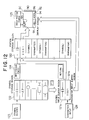
- FIG. 7 there is shown an example of hardware arrangements of a programming apparatus and a programmable controller, according to the present invention, which loads a sequence program formed by this programming apparatus.
- the programming apparatus PGM surrounded by a dot and dash line of this figure performs operations of the present invention.
- the programming apparatus PGM is so arranged by a main memory 72 functioning as an internal storage device for storing a control program, data and the like used for programming; a hard disk apparatus (DISK) 73 and a floppy disk apparatus (FDO) 74 functioning as an external storage apparatus; a CRT (cathode-ray tube) functioning as a display apparatus; a keyboard (KB) 76 functioning as an input apparatus; a printer 78 functioning as a printing apparatus; a serial interface 79 for transmitting a formed sequence program; and, a central processing unit (CPU) for controlling an overall operation of the programming apparatus.
- a main memory 72 functioning as an internal storage device for storing a control program, data and the like used for programming
- DISK hard disk apparatus
- FDO floppy disk apparatus
- CTR cathode-ray tube
- KB keyboard
- printer 78 functioning as a printing apparatus
- serial interface 79 for transmitting a formed sequence program
- CPU central processing unit
- the programmable controller PCS is constructed of an interface 81 for receiving the sequence program transmitted from the programming apparatus PCS; a memory for storing the received sequence program; a CPU for executing this program; and an input/output device (I/O) 84 for transmitting/receiving data between devices under control.
- I/O input/output device
- CPU 71 executes a display screen control of CRT 75; forms a ladder program in response to key entries by a user via the keyboard 76; and stores the formed ladder program into the hard disk 73. Upon completion of a series of program, CPU 71 transfers the program via the serial interface 79 to the programmable controller PCS in accordance with the key operation by the user.
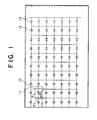
- Fig. 1 represents a display screen of the programmable controller PCS of the programming apparatus according to one preferred embodiment of the present invention. That is, this drawing is a ladder diagram for displaying an arrangement of elements which can be arranged within one display screen.
- reference numeral 11 denotes a large cursor.
- This large cursor 11 is moved by every 1 element in unit of element "E” and indicates an overall element E (namely, an element "E” constructed of a symbol element E1 and a character element E2), in other words, an overall region surrounded by a thick frame either at higher brightness, or a reverse mode representation.
- an element namely, an element "E" constructed of a symbol element E1 and a character element E2
- E2 an overall region surrounded by a thick frame either at higher brightness, or a reverse mode representation.
- a small cursor 12 is displayed which is moved by every 1 character within this large cursor 11.
- Fig. 2 shows an example of a comparing box 23 and a calculating box 24 which have been, very recently, developed as an application instruction of a ladder diagram.
- This comparing box 23 performs the same operation as a relay contact in such a manner that a comparison instruction of input/output data is inputted and a comparison is made whether or not a condition thereof is satisfied.
- the calculating box 24 executes a calculation when an arithmetic calculation instruction is entered and conditions of ladder diagrams positioned before and after the calculating box 24 are satisfied.
- overall boxes corresponding to the element E are designated by the large cursor 21 and a content within the large cursor 21 is displayed at higher brightness or under reverse condition.
- the comparison instruction or the like is entered into the large cursor 21, namely the relevant box by the small cursor 22 which can be moved only in the large cursor 21.
- FIG. 3A represents a key operation sequence for the cursor corresponding to a relay contact.
- the large cursor is moved to a desirable element position by operating a cursor moving key arranged on the keyboard 76.
- the representation of the state S to is made and then a region within the large cursor is displayed at higher brightness or reverse mode.
- a symbol key "F2" of the b-contact arranged on the keyboard 76 is depressed under this condition.
- symbol keys have been determined with respect to each of symbol and element sorts, and a desirable element can be designated/inputted by depressing the corresponding symbol key.
- the function keys are employed as the symbol keys. For example, the symbol elements corresponding to the function keys F1 to F10 arranged on the keyboard 76 are displayed at the lower side of the display screen shown in Fig. 8A, for the sake of easy understanding to users.
- Fig. 3C is an explanatory diagram for showing such a corresction case that "X423" is mistakenly inputted instead of "X123" as the input number.
- the small cursor is moved by three characters in the left direction so as to be positioned under "4".
- the numeral key "1" provided on the keyboard 76 is depressed under overwriting state, this can be amended by the correct input number. In this case, such an amendment is completed by operating the keys 4 times.
- Fig. 4A represents a key operation sequence when the large cursor is moved to the comparing box
- Fig. 4B shows an example of screens corresponding to the states S to , S t1 , and S t2 as shown in the upper side of Fig. 4A.
- the large cursor is moved to a desirable element position by operating the cursor moving key arranged on the keyboard 76 (S to ) and the symbol key "F3" indicative of the comparing box is depressed.
- the state is moved to the state S t1 .
- the small cursor is moved in a similar manner to that of Fig. 3A (not shown in Figs. 4, 5 and 6), in order to enter the comparison instruction.
- the "return" key is depressed, the condition is moved to the state S t2 where the above-described comparison instruction is inputted and displayed within the box.
- Fig. 5A represents a key operation sequence in case that the large cursor is moved to the relay coil
- Fig. 5B represents an example of display screens corresponding to the states S to , S t1 and S t2 shown in the upper side of Fig. 5A
- Fig. 6A represents a key operation sequence in case that the large cursor is moved to the calculating box
- Fig. 6B represents an example of display screens corresponding to the states S to , S t1 and S t2 shown at the upper side of Fig. 6A.
- the input area is largely expanded so as to easily input the input number and comparison instruction. This is because the data correction may be simply corrected by way of the small cursor.
- FIG. 8A and 8B Another preferred embodiment capable of readily correcting the input data is shown in Figs. 8A and 8B.
- a larger representation than that of Fig. 3B is made.
- a representation of symbol "1 b" shown in Fig. 8A is so made that sizes of the contact symbol and input number are two times larger than those of the previous symbol and number, whereby the input position and input data can be readily recognized.
- the elements designated by this cursor 11 have been displayed at the higher brightness or in the reverse mode by moving the large cursor 11.
- other display conditions such as color representations, sizes of lines and characters, which are distinguishable from the above elements, may be employed. In other words, these elements may be distinguishably displayed as compared with other elements.
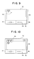
- FIG. 9 shows an example of display screen of a programming apparatus according to another preferred embodiment of the present invention.
- a display screen SC is subdivided into a circuit display region 90 and a circuit input region 96.
- the circuit input region 96 includes a symbol input region 91 and a parameter input region 92.
- an internal storage area (will be discussed later) and a key operation (will be explained later) are independent from each other and a symbol and a parameter may be inputted asynchrously. That is to say, either one of the symbol and parameter may be inputted, otherwise both of them may be alternately inputted. Even when both of them are alternately inputted, either the symbol or parameter may be firstly entered.
- a symbol is inputted by depressing a plurality of specific keys corresponding to the symbols, otherwise a plurality of symbols which have been previously registered may be cyclically inputted in turn in accordance with depression of a single key. In a concrete example (will be discussed later), the latter method has been employed.
- a parameter is inputted by operating an alphabetic key and a numeral key.
- Fig. 12 is a schematic block diagram for representing a functional arrangement of the programming apparatus according to this preferred embodiment.
- a symbol has been registered in a symbol storage region 122 functioning as the internal storage area.
- the symbol designated by a symbol pointer 123 is termporarily stored into a symbol input buffer region 121 a as the internal storage area for inputting the symbol, and the symbol pointer 123 is successively updated.
- This symbol is displayed on a symbol input region 91 on the display screen SC.
- a parameter is temporarily stored in a character input region 121b b functioning as the internal storage area for the parameter by depressing the alphabetic key and numeric key.
- This parameter is displayed on a parameter input region 122 on the display screen SC.
- a parameter input cursor 94 is controlled by a character input position pointer 128. The parameter input cursor 94 is freely movable within the parameter input region 92 in response to an instruction made by a user, so that amendments of erroneous inputs can be simply performed.
- an input position pointer 124 designates a storage area of a circuit symbol, and a subsequent storage area becomes a storage area of the corresponding parameter.
- a circuit of a circuit display area 90 on the display screen SC is displayed. In this example, both the symbol and parameter which have been determined are displayed at an input position cursor 93 of the circuit dispaly region 90.
- the input position cursor 93 is moved to the next input position. Also after the input decision, since both the symbol input region 91 and the parameter input region 92 are kept under the previous condition, this condition may be utilized as the subsequent input.
- the position of the input position cursor 93 is controlled by the display position pointer 125.
- Fig. 10 represents an example of a display screen where a circuit which has been formed is corrected.
- the input position cursor 93 is moved to a position of a symbol to be amended.
- the symbol and parameter which have been displayed at a position of the input position cursor 93 are stored into a symbol input buffer region 121 a and a parameter input buffer region 121b, and then displayed on a symbol input region 91 and a parameter input region 92.
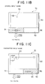
- a further preferred embodiment according to the present invention will now be described with reference to Figs. 11A to 11C.
- the circuit input mode a symbol/parameter simultaneous input mode; a symbol input mode; and a parameter input mode.
- the input mode is reportedly varied as follows in this order the symbol/parameter simultaneous input mode; the symbol input mode; the parameter input mode; and the symbol/parameter simultaneous input mode.
- the background color of the input unit by which the data can be entered is varied, whereby it represents which mode has been selected.
- the same circuit arrangements as shown in Figs. 7 and 12 are avaialble as an arrangement of the programming apparatus according to this preferred embodiment.
- Fig. 11A represents an example of a display screen with respect to the symbol/parameter input mode (mode 1), and an input method is the same as that of the previous preferred embodiment. That is to say, any one of the symbol and parameter can be inputted, and when the "return" key is depressed, both the symbol and parameter are stored at the designated position of the edition storage region 120.
- Fig. 11 B is another example of a display screen for the symbol input mode (mode 2). In this mode, after the symbol has been inputted into the symbol input region 91, only the symbol may be continuously inputted, changed by determining the "return" key.
- Fig. 11 C shows an example of a display screen for the parameter input mode (mode 3). In this mode, after the parameter has been inputted into the parameter input region 93, only the parameter can be continuously inputted/amended by surely depressing the "return" key.
- the content of the symbol input buffer region 121 a is neither changed even by the movement of the input position cursor 93, nor be transferred to the edition storage region 120 by depressing the return key. As a consequence, there is no risk that the symbol is erroneously changed when amending the parameter.
- Figs. 13 to 16 are flow charts for explaining a process flow of the preferred embodiment which has been explained in Figs. 3A to 3C.
- Fig. 13 represents a main process flow.
- an editing screen is displayed at first (601).
- the content is read out from the external storage apparatus and the content thereof is displayed.
- a selection is made of a desirable input mode from the three input modes.
- a judgement is performed with respect to the selected input mode (603, 604) and then the process is advanced to the process of the selected mode (605, 606 or 607).
- another judgement is made whether or not the process shown in Fig. 13 has been accomplished (608). If the process has not yet been ended, the process is returned to a step 603.
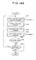
- Figs. 14A to 14E show the detailed process flow of the mode 1 and Fig. 14A represents a main process flow thereof.
- a movement process of the input position cursor 93 for the mode 1 is first performed (701). Then, a symbol input process (703) is performed, and thereafter an input data setting process (704) for the mode 1 is carried out. Subsequently, a judgement is made whether or not this process shown in this drawing is ended (705), and if this process is not ended, a check is made whether or not there is a change in the input mode (706). If no change is made, the process is returned to the process 701, whereas if the change is made, this process as defined in this figure is accomplished.
- Fig. 14B represents a detailed process flow of the input position cursor moving process 701 as defined in Fig. 14A.
- a check is done whether or not the movement key (although not shown, for instance this key may be a key "-" or a key "-") of the input position cursor 9 is inputted (710), and then if no movement key is entered, the process of this drawing is ended. Conversely, if the movement key is entered, the input position pointer 124 is updated in accordance with this input (712) and the display position pointer 125 is also updated.
- another check is made whether or not the symbol has been previously set at this relevant position (714), and if no symbol has been set there, the process is advanced to a process 716.
- Fig. 14C represents a detailed process flow of the symbol input process 702 shown in Fig. 14A. It should be noted that this process is commonly used as in a symbol input process 801 of a mode 2 (will be discussed later).
- a check is made whether or not the "F1" key is inputted (720), if the "F1" key is not inputted, this process is accomplished. However, if the "F1" key is inputted, the process is advanced to a process 721. At the process 721, the symbol within the symbol storage region 122 indicated by the present symbol pointer 123 is duplicated to the symbol input buffer region 121a. Thereafter, the symbol pointer 123 is updated (722).
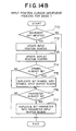
- Fig. 14D is a flow chart for representing a detailed operation of the parameter input process 703 shown in Fig. 14A. This process is commonly used as that of a parameter input process 901 for the mode 3 (will be discussed later).
- the insertion mode of the character input is selected (730, 746).
- the movement key of the cursor 94 for the character input is not shown, a different key from the movement keys "-" and key “-” of the input position cursor 93 is employed.
- the moving operation of the parameter input cursor 94 can be freely performed (731, 742 to 745) within the input available range without changing the contents of the parameter input buffer region 121 b.
- the characters positioned at the left side of the cursor may be successively erased by operating the "backward" key (732, 739 to 741
- the characters may be inputted, depending upon the selection of the insert mode, while maintaining the previously inputted contents or amending these contents (733 to 738).
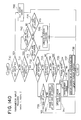
- Fig. 14E represents a detailed process flow of the input data setting process 704 shown in Fig. 14A.
- This process corresponds to such a process that both a symbol and a parameter which have been held in the circuit input region 96 on the display screen are transferred and duplicated into the circuit display region 90.
- a first check is made whether or not the "return" key is inputted (750). If no return key is entered, this process is ended. Conversely, if the return key is inputted, the process is advanced to a process at 751. At this process 751, if the symbol has been displayed on the symbol input region 91 (namely, if the symbol is held at the symbol storage region 121 a), this symbol is stored into the position which has been designated by the input position pointer 124 of the edition storage region 120.
- this symbol is displayed at a position indicated by the display position pointer 93 of the circuit display region 90 (753).
- the content of the parameter input region 92 is displayed on the circuit display region (755, 756).
- both the input position pointer 124 and display position pointer 125 are updated to the next position (757, 758).
- Fig. 15A represents a process flow of a main process of the mode 2.
- a process for moving the input position cursor of the mode 2 is performed (800).
- a process for setting input data for the mode 2 is performed (802).
- a check is made whether or not this process is accomplished (803). If this process is not ended, a check is made whether or not the input mode is changed (804). If no input mode is changed, the process operation is returned to the provides process 800, whereas if the input mode is changed, this process is accomplished.
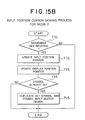
- Fig. 15B represents a detailed process flow of the input position cursor moving process 800 used in the mode 2 of Fig. 15A. This process corresponds to a part of the input position cursor moving process used in the mode 1 as shown in Fig. 14B, from which the processes 716 and 717 for duplicating the previously set parameter into the parameter input region 92 have been deleted.
- Fig. 15C indicates a detailed process flow of the input data setting process 802 used in the mode 2 shown in Fig. 15A. This process corresponds to a part of the process shown in Fig. 14E, and is the same as the last-mentioned process from which the processes 754 to 756 related to the parameter setting operation have been deleted.
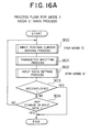
- Fig. 16A represents a process flow for a main process of the mode 3.
- an input position cursor moving process used in the mode 3 is performed (900), and thereafter an input process of the parameter is effected (901).
- an input data setting process used in the mode 3 is carried out (902).
- a check is made whether or not this process is accomplished (903). If this process is not yet ended, then another check is made whether or not the input mode is changed (904). If no input mode is changed, then the process is returned to the previous process 900. If the input mode is changed, then this process is completed.
- Fig. 16B represents a detailed process flow of the input position cursor moving process 900 used in the mode 3 shown in Fig. 16A. This process corresponds to a part of the input position cursor moving process used in the mode 1 shown in Fig. 14B, and is identical to this cursor moving process other than the processes 714 and 715 for duplicating the previously set symbol into the symbol input region 11.
- Fig. 16C represents a detailed process flow of the input data setting process 902 used in the mode 2 shown in Fig. 16A. This process corresponds to a part of the process shown in Fig. 14E, and is identical to the last-mentioned process other than the processes 751 to 753 related to the symbol setting operations.
- a user can input symbols and/or parameters according to a desirable input sequence suitable for the user.
- both the symbol and parameter which have been previously inputted are left in the respective symbol input region and parameter input region, these symbols and parameters can be utilized in the subsequent input operation. As a consequence, a total number of key input operation is reduced so that workloads given to the user may be reduced.
- both the symbol and parameter located at this amending position are inputted/displayed in the respective symbol input region and parameter input region. Then, since the amendment and change are performed with employment of these symbol and parameter, a total key input number required for amending the circuit portion may be reduced by 1/2 to 1/10.
Applications Claiming Priority (4)
| Application Number | Priority Date | Filing Date | Title |
|---|---|---|---|
| JP248735/90 | 1990-09-20 | ||
| JP02248735A JP3123720B2 (ja) | 1990-09-20 | 1990-09-20 | プログラマブルコントローラのプログラミング方法及びプログラミング装置 |
| JP324885/90 | 1990-11-26 | ||
| JP2324885A JP2898398B2 (ja) | 1990-11-26 | 1990-11-26 | プログラマブルコントローラのプログラミング装置 |
Publications (2)
| Publication Number | Publication Date |
|---|---|
| EP0477760A1 true EP0477760A1 (fr) | 1992-04-01 |
| EP0477760B1 EP0477760B1 (fr) | 1996-07-24 |
Family
ID=26538924
Family Applications (1)
| Application Number | Title | Priority Date | Filing Date |
|---|---|---|---|
| EP91115867A Expired - Lifetime EP0477760B1 (fr) | 1990-09-20 | 1991-09-18 | Méthode de programmation et appareil pour automate programmable |
Country Status (4)
| Country | Link |
|---|---|
| US (1) | US5699080A (fr) |
| EP (1) | EP0477760B1 (fr) |
| DE (1) | DE69121034T2 (fr) |
| ES (1) | ES2090194T3 (fr) |
Cited By (4)
| Publication number | Priority date | Publication date | Assignee | Title |
|---|---|---|---|---|
| WO1999028794A2 (fr) * | 1997-11-26 | 1999-06-10 | Moeller Gmbh | Mini-automate |
| DE19822454A1 (de) * | 1998-04-17 | 1999-10-21 | Moeller Gmbh | Elektronische Verdrahtung von Kontaktanschlüssen und Funktionsbausteinen |
| EP1036352B1 (fr) * | 1997-12-01 | 2003-02-05 | Siemens Aktiengesellschaft | Procede de definition et de parametrage d'interfaces assiste par ecran |
| US20160004242A1 (en) * | 2013-03-07 | 2016-01-07 | Mitsubishi Electric Corporation | Ladder-program display program and ladder-program display apparatus |
Families Citing this family (6)
| Publication number | Priority date | Publication date | Assignee | Title |
|---|---|---|---|---|
| CN1153444C (zh) * | 1995-10-02 | 2004-06-09 | 佳能株式会社 | 图象处理装置及方法 |
| US6043700A (en) * | 1997-10-17 | 2000-03-28 | National Semiconductor Corporation | Analog multiplier with thermally compensated gain |
| US6952811B1 (en) * | 1998-07-30 | 2005-10-04 | Mitsubishi Denki Kabushiki Kaisha | Ladder circuit editing system |
| DE602005015052D1 (de) * | 2004-03-31 | 2009-08-06 | Omron Tateisi Electronics Co | Vorrichtung zur Entwicklungsunterstützung |
| JP5454783B2 (ja) * | 2009-03-13 | 2014-03-26 | オムロン株式会社 | Plcのプログラミングにおける変数名の入力支援方法、plcのプログラミングにおける変数名の入力支援装置、及びコンピュータプログラム |
| JP5591271B2 (ja) * | 2012-03-26 | 2014-09-17 | 三菱電機株式会社 | ロジック図面処理装置及びその処理方法 |
Citations (2)
| Publication number | Priority date | Publication date | Assignee | Title |
|---|---|---|---|---|
| GB2077966A (en) * | 1980-05-30 | 1981-12-23 | Hitachi Ltd | Programming equipment |
| US4445169A (en) * | 1980-06-13 | 1984-04-24 | The Tokyo Electric Co., Inc. | Sequence display apparatus and method |
Family Cites Families (15)
| Publication number | Priority date | Publication date | Assignee | Title |
|---|---|---|---|---|
| JPS55135908A (en) * | 1979-04-11 | 1980-10-23 | Hitachi Ltd | Sequence program input device |
| JPS5611502A (en) * | 1979-07-09 | 1981-02-04 | Toyoda Mach Works Ltd | Program correction unit in sequence controller |
| JPS5615891A (en) * | 1979-07-19 | 1981-02-16 | Toshimitsu Matsubara | Sewage purifying apparatus |
| DE2939489A1 (de) * | 1979-09-28 | 1981-05-14 | Siemens Ag | System zur lokalisierung von bereichen bei gemischter text-/bildbearbeitung am bildschirm |
| EP0051294B1 (fr) * | 1980-10-31 | 1986-10-01 | Kabushiki Kaisha Toshiba | Circuit de conversion de format d'image |
| US4488258A (en) * | 1982-09-20 | 1984-12-11 | Allen-Bradley | Programmable controller with control program comments |
| US4656603A (en) * | 1984-03-01 | 1987-04-07 | The Cadware Group, Ltd. | Schematic diagram generating system using library of general purpose interactively selectable graphic primitives to create special applications icons |
| JPS60221807A (ja) * | 1984-04-19 | 1985-11-06 | Toshiba Mach Co Ltd | デイスプレイ装置におけるリレ−ラダ−図の表示方法 |
| JPH0652472B2 (ja) * | 1984-07-23 | 1994-07-06 | インターナショナル・ビジネス・マシーンズ・コーポレーション | イメージ処理方法 |
| JPS61213892A (ja) * | 1985-03-19 | 1986-09-22 | 株式会社アスキ− | デイスプレイ・コントロ−ラ |
| US4831580A (en) * | 1985-07-12 | 1989-05-16 | Nippon Electric Industry Co., Ltd. | Program generator |
| JPS6247095A (ja) * | 1985-08-20 | 1987-02-28 | インタ−ナショナル ビジネス マシ−ンズ コ−ポレ−ション | ボツクス・カ−ソル表示方法 |
| US5021973A (en) * | 1986-01-16 | 1991-06-04 | International Business Machines Corporation | Method for assisting the operator of an interactive data processing system to enter data directly into a selected cell of a spreadsheet |
| JP2738851B2 (ja) * | 1988-10-21 | 1998-04-08 | 株式会社日立製作所 | 複数カーソルによる入力データ処理表示方法 |
| JPH02160287A (ja) * | 1988-12-14 | 1990-06-20 | Nec Corp | カーソル表示回路 |
-
1991
- 1991-09-18 DE DE69121034T patent/DE69121034T2/de not_active Expired - Lifetime
- 1991-09-18 EP EP91115867A patent/EP0477760B1/fr not_active Expired - Lifetime
- 1991-09-18 ES ES91115867T patent/ES2090194T3/es not_active Expired - Lifetime
-
1993
- 1993-08-09 US US08/110,191 patent/US5699080A/en not_active Expired - Lifetime
Patent Citations (2)
| Publication number | Priority date | Publication date | Assignee | Title |
|---|---|---|---|---|
| GB2077966A (en) * | 1980-05-30 | 1981-12-23 | Hitachi Ltd | Programming equipment |
| US4445169A (en) * | 1980-06-13 | 1984-04-24 | The Tokyo Electric Co., Inc. | Sequence display apparatus and method |
Cited By (7)
| Publication number | Priority date | Publication date | Assignee | Title |
|---|---|---|---|---|
| WO1999028794A2 (fr) * | 1997-11-26 | 1999-06-10 | Moeller Gmbh | Mini-automate |
| WO1999028794A3 (fr) * | 1997-11-26 | 1999-10-07 | Kloeckner Moeller Gmbh | Mini-automate |
| US6633278B1 (en) | 1997-11-26 | 2003-10-14 | Moeller Gmbh | Mini controller |
| EP1036352B1 (fr) * | 1997-12-01 | 2003-02-05 | Siemens Aktiengesellschaft | Procede de definition et de parametrage d'interfaces assiste par ecran |
| US7017121B1 (en) | 1997-12-01 | 2006-03-21 | Siemens Aktiengesellschaft | Method for visual display unit-based definition and parametrization of interfaces |
| DE19822454A1 (de) * | 1998-04-17 | 1999-10-21 | Moeller Gmbh | Elektronische Verdrahtung von Kontaktanschlüssen und Funktionsbausteinen |
| US20160004242A1 (en) * | 2013-03-07 | 2016-01-07 | Mitsubishi Electric Corporation | Ladder-program display program and ladder-program display apparatus |
Also Published As
| Publication number | Publication date |
|---|---|
| DE69121034T2 (de) | 1997-02-20 |
| DE69121034D1 (de) | 1996-08-29 |
| EP0477760B1 (fr) | 1996-07-24 |
| US5699080A (en) | 1997-12-16 |
| ES2090194T3 (es) | 1996-10-16 |
Similar Documents
| Publication | Publication Date | Title |
|---|---|---|
| EP0249399B1 (fr) | Méthode et appareil de commande de fenêtres multiples pour un poste de travail avec fonction de fenêtres multiples | |
| US5287449A (en) | Automatic program generation method with a visual data structure display | |
| US5699080A (en) | Programming method and apparatus for programmable controller | |
| JPH0388087A (ja) | 文書読取装置 | |
| US5130939A (en) | Compact electronic calculator capable of displaying matrix element data under actual matrix form | |
| JPH025102A (ja) | Pcラダー図の入力方式 | |
| JPH0916801A (ja) | コマンド指定装置 | |
| JP2898398B2 (ja) | プログラマブルコントローラのプログラミング装置 | |
| EP0551098B1 (fr) | Méthode d'affichage d'un système de programmation pour une commande programmable | |
| JP2875135B2 (ja) | プログラマブルコントローラ用プログラム装置 | |
| JPH0221320A (ja) | 編集機能付ヘルプ機能を有する情報処理装置 | |
| EP0315172B1 (fr) | Méthode de génération automatique de programmes avec visualisation de la structure des données | |
| JP3123720B2 (ja) | プログラマブルコントローラのプログラミング方法及びプログラミング装置 | |
| JPH0119170B2 (fr) | ||
| JPH0580814A (ja) | プログラマブルコントローラ用プログラミング装置 | |
| JP3492146B2 (ja) | プログラマブルコントローラのプログラミング装置 | |
| JP2965811B2 (ja) | 情報処理装置および表示方法 | |
| JP3246952B2 (ja) | Cad処理方法および装置 | |
| JPH04232510A (ja) | ロボット操作器の編集装置 | |
| JPH05108635A (ja) | 文字表示装置 | |
| JPH06324777A (ja) | 情報処理システムのデータ入力方法 | |
| JPH0330051A (ja) | 文書処理装置 | |
| JPH06215093A (ja) | 図形処理装置 | |
| JPH10214072A (ja) | 情報処理装置 | |
| JPH05233049A (ja) | 工具経路確認方法 |
Legal Events
| Date | Code | Title | Description |
|---|---|---|---|
| PUAI | Public reference made under article 153(3) epc to a published international application that has entered the european phase |
Free format text: ORIGINAL CODE: 0009012 |
|
| AK | Designated contracting states |
Kind code of ref document: A1 Designated state(s): DE ES FR GB IT |
|
| 17P | Request for examination filed |
Effective date: 19920921 |
|
| 17Q | First examination report despatched |
Effective date: 19940923 |
|
| GRAH | Despatch of communication of intention to grant a patent |
Free format text: ORIGINAL CODE: EPIDOS IGRA |
|
| GRAH | Despatch of communication of intention to grant a patent |
Free format text: ORIGINAL CODE: EPIDOS IGRA |
|
| GRAA | (expected) grant |
Free format text: ORIGINAL CODE: 0009210 |
|
| AK | Designated contracting states |
Kind code of ref document: B1 Designated state(s): DE ES FR GB IT |
|
| REF | Corresponds to: |
Ref document number: 69121034 Country of ref document: DE Date of ref document: 19960829 |
|
| REG | Reference to a national code |
Ref country code: ES Ref legal event code: FG2A Ref document number: 2090194 Country of ref document: ES Kind code of ref document: T3 |
|
| ET | Fr: translation filed | ||
| ITF | It: translation for a ep patent filed |
Owner name: MODIANO & ASSOCIATI S.R.L. |
|
| ET | Fr: translation filed | ||
| REG | Reference to a national code |
Ref country code: ES Ref legal event code: FG2A Ref document number: 2090194 Country of ref document: ES Kind code of ref document: T3 |
|
| PLBI | Opposition filed |
Free format text: ORIGINAL CODE: 0009260 |
|
| PLBF | Reply of patent proprietor to notice(s) of opposition |
Free format text: ORIGINAL CODE: EPIDOS OBSO |
|
| 26 | Opposition filed |
Opponent name: SIEMENS AG Effective date: 19970423 |
|
| PLBF | Reply of patent proprietor to notice(s) of opposition |
Free format text: ORIGINAL CODE: EPIDOS OBSO |
|
| PLBO | Opposition rejected |
Free format text: ORIGINAL CODE: EPIDOS REJO |
|
| PLBN | Opposition rejected |
Free format text: ORIGINAL CODE: 0009273 |
|
| STAA | Information on the status of an ep patent application or granted ep patent |
Free format text: STATUS: OPPOSITION REJECTED |
|
| 27O | Opposition rejected |
Effective date: 19990416 |
|
| REG | Reference to a national code |
Ref country code: GB Ref legal event code: IF02 |
|
| PGFP | Annual fee paid to national office [announced via postgrant information from national office to epo] |
Ref country code: ES Payment date: 20100902 Year of fee payment: 20 |
|
| PGFP | Annual fee paid to national office [announced via postgrant information from national office to epo] |
Ref country code: FR Payment date: 20100907 Year of fee payment: 20 Ref country code: IT Payment date: 20100720 Year of fee payment: 20 |
|
| PGFP | Annual fee paid to national office [announced via postgrant information from national office to epo] |
Ref country code: GB Payment date: 20100902 Year of fee payment: 20 |
|
| PGFP | Annual fee paid to national office [announced via postgrant information from national office to epo] |
Ref country code: DE Payment date: 20100728 Year of fee payment: 20 |
|
| REG | Reference to a national code |
Ref country code: DE Ref legal event code: R071 Ref document number: 69121034 Country of ref document: DE |
|
| REG | Reference to a national code |
Ref country code: DE Ref legal event code: R071 Ref document number: 69121034 Country of ref document: DE |
|
| REG | Reference to a national code |
Ref country code: GB Ref legal event code: PE20 Expiry date: 20110917 |
|
| PG25 | Lapsed in a contracting state [announced via postgrant information from national office to epo] |
Ref country code: GB Free format text: LAPSE BECAUSE OF EXPIRATION OF PROTECTION Effective date: 20110917 |
|
| REG | Reference to a national code |
Ref country code: ES Ref legal event code: FD2A Effective date: 20120110 |
|
| PG25 | Lapsed in a contracting state [announced via postgrant information from national office to epo] |
Ref country code: ES Free format text: LAPSE BECAUSE OF EXPIRATION OF PROTECTION Effective date: 20110919 |
|
| PG25 | Lapsed in a contracting state [announced via postgrant information from national office to epo] |
Ref country code: DE Free format text: LAPSE BECAUSE OF EXPIRATION OF PROTECTION Effective date: 20110919 |