EP0477357B1 - Verfahren und vorrichtung zur herstellung von mit einem schutzüberzug versehenen kantenschutzleisten aus karton und so hergestellte kantenschutzleisten - Google Patents
Verfahren und vorrichtung zur herstellung von mit einem schutzüberzug versehenen kantenschutzleisten aus karton und so hergestellte kantenschutzleisten Download PDFInfo
- Publication number
- EP0477357B1 EP0477357B1 EP91908922A EP91908922A EP0477357B1 EP 0477357 B1 EP0477357 B1 EP 0477357B1 EP 91908922 A EP91908922 A EP 91908922A EP 91908922 A EP91908922 A EP 91908922A EP 0477357 B1 EP0477357 B1 EP 0477357B1
- Authority
- EP
- European Patent Office
- Prior art keywords
- strip
- cardboard
- covering
- strips
- folding
- Prior art date
- Legal status (The legal status is an assumption and is not a legal conclusion. Google has not performed a legal analysis and makes no representation as to the accuracy of the status listed.)
- Expired - Lifetime
Links
Images


Classifications
-
- B—PERFORMING OPERATIONS; TRANSPORTING
- B31—MAKING ARTICLES OF PAPER, CARDBOARD OR MATERIAL WORKED IN A MANNER ANALOGOUS TO PAPER; WORKING PAPER, CARDBOARD OR MATERIAL WORKED IN A MANNER ANALOGOUS TO PAPER
- B31F—MECHANICAL WORKING OR DEFORMATION OF PAPER, CARDBOARD OR MATERIAL WORKED IN A MANNER ANALOGOUS TO PAPER
- B31F1/00—Mechanical deformation without removing material, e.g. in combination with laminating
- B31F1/0003—Shaping by bending, folding, twisting, straightening, flattening or rim-rolling; Shaping by bending, folding or rim-rolling combined with joining; Apparatus therefor
- B31F1/0006—Bending or folding; Folding edges combined with joining; Reinforcing edges during the folding thereof
- B31F1/0009—Bending or folding; Folding edges combined with joining; Reinforcing edges during the folding thereof of plates, sheets or webs
- B31F1/0019—Bending or folding; Folding edges combined with joining; Reinforcing edges during the folding thereof of plates, sheets or webs the plates, sheets or webs moving continuously
- B31F1/0029—Folding edges; Folding edges combined with joining; Reinforcing edges during the folding thereof, e.g. by introducing a thread; Folding the edges of a sheathing
-
- B—PERFORMING OPERATIONS; TRANSPORTING
- B31—MAKING ARTICLES OF PAPER, CARDBOARD OR MATERIAL WORKED IN A MANNER ANALOGOUS TO PAPER; WORKING PAPER, CARDBOARD OR MATERIAL WORKED IN A MANNER ANALOGOUS TO PAPER
- B31F—MECHANICAL WORKING OR DEFORMATION OF PAPER, CARDBOARD OR MATERIAL WORKED IN A MANNER ANALOGOUS TO PAPER
- B31F1/00—Mechanical deformation without removing material, e.g. in combination with laminating
- B31F1/0003—Shaping by bending, folding, twisting, straightening, flattening or rim-rolling; Shaping by bending, folding or rim-rolling combined with joining; Apparatus therefor
- B31F1/0006—Bending or folding; Folding edges combined with joining; Reinforcing edges during the folding thereof
- B31F1/0009—Bending or folding; Folding edges combined with joining; Reinforcing edges during the folding thereof of plates, sheets or webs
- B31F1/0019—Bending or folding; Folding edges combined with joining; Reinforcing edges during the folding thereof of plates, sheets or webs the plates, sheets or webs moving continuously
Definitions
- the invention relates to a method and a device for manufacturing cardboard angles provided with a coating.
- the invention also relates to the angles made according to the method and / or by means of the device according to the invention.
- angles To protect certain edges of angles, in particular in packages surrounded by strips, it is known to use angles.
- the strips are formed by a complex based on aluminum and / or polyethylene.
- the inner face of at least the second coating strip and / or the face of the cardboard strip to which it is applied is previously heated before being applied and glued by pressure.
- the longitudinal folding can be carried out either so that the second covering strip forms the inside surface of the angle iron, or in opposite directions so that the second covering strip forms the outside surface of the angle iron.
- the invention also relates to a device for implementing the method and which is remarkable in that it comprises a supply and gluing system in superposition of at least one strip of cardboard on a first strip of coating, a wrapper to fold the first coating strip, an applicator downstream of the wrapper to apply the second coating strip and a folder to fold the assembly longitudinally.
- the applicator comprises a heating device and at least one pressure roller.
- the wrapper has two lateral wings each provided with an inward fold to form a passage so that the cross section of said passage decreases both in width and in height over at least part of the length of said wrapper in the direction of travel of the strips.
- the wings of the wrapper are mounted so that their reciprocal spacing is adjustable, in order to be able to easily adapt said wrapper to the different strip widths.
- the invention also relates to the angles manufactured according to the method and / or by means of the abovementioned device.
- an angle iron according to the invention is remarkable in that it comprises at least one strip of cardboard thus forming two faces of a complex which is caught between two strips of covering, one of which is wider than said cardboard strip (s) is glued to one side of the complex and folded over to the other side of the complex, while the other covering strip, of a width equivalent to that of the cardboard strip (s) , is applied to said other face of the complex and to the folds of the first covering strip.
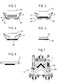
- FIGS. 1 to 7 several strips of cardboard of the same width are brought into longitudinal superposition, here 1a, 1b, 1c by means of a supply device. (not shown) comprising for example several reels.
- the strips are brought to one another with the interposition of a layer of glue by means, for example, of glueers (not shown). If the figures show 3 strips of cardboard, there can of course be more, or less.
- the thicknesses shown are completely arbitrary.
- the three strips 1a to 1c arrive above a first covering strip 2a slightly wider than said cardboard strips and also covered on top with a layer of glue.
- the strip 2a is for example based on polyethylene and / or aluminum.
- This first manufacturing phase is shown diagrammatically in FIG. 2.
- the assembly formed by the covering strip 2a and by the cardboard strips 1a to 1c then enters a wrapper 3 (phase shown diagrammatically in FIG. 3).
- the wrapper 3 which will be described in more detail below, is intended to fold the edges of the strip 2a on the sides of the cardboard strips (FIG. 3) until it forms folds above the free face of the last strip of cardboard 1c (FIG. 4), the complex (1a, 1b, 1c, 2a) thus formed leaving the wrapper 3 as shown in FIG. 5.
- a second covering strip 2b of the same kind as the strip 2a but with a width similar to that of the cardboard strips 1a to 1c is brought as shown in FIGS. 1 to 5, downstream of the wrapper 3 to be applied to the aforementioned complex.
- the bands 2a and 2b are shown in the drawings in solid lines.
- this strip 2b In order to facilitate the bonding of this strip 2b on the folds of the strip 2a and the upper face of the last strip 1c, the latter and / or the inner face facing the strip 2b is previously heated by means of a device for heating 4 (figure 1). The application of the strip 2b is further ensured by a pressure roller 5 as shown in FIGS. 1 and 6.
- the folder 6 comprises two chains 6a, 6b each formed by a plurality of chevron-shaped links in FIG. 7, fitting into each other over a certain length so as to fold the complex (1a, 1b, 1c, 2a, 2b) longitudinally by enclosing it to form an angle 7 ( Figures 1 and 7).
- the wrapper 3 comprises two symmetrical lateral wings 3a, 3b (FIGS. 8 to 11), the spacing of which is preferably adjustable by means of, for example, knobs 8a, 8b (FIGS. 1, 8 and 9) intended to actuate screws d 'spacing.
- the wings 8a, 8b of the wrapper 3 have inward folds and a particular shape as the perspectives of Figures 10 and 11 clearly show, such that the cross section of the passage thus created decreases in width and height over part of the length of said wrapper in the direction of travel of the strips. It is clear that the wrapper is provided as already explained for partially wrapping the cardboard strips with the strip 2a, by folding the edges of the latter.
- the angle 7 thus produced is particularly resistant and waterproof depending on the nature of the covering strips 2a, 2b.
- easy continuous manufacturing is possible with a device according to the invention.
Landscapes
- Engineering & Computer Science (AREA)
- Mechanical Engineering (AREA)
- Making Paper Articles (AREA)
- Machines For Manufacturing Corrugated Board In Mechanical Paper-Making Processes (AREA)
- Finishing Walls (AREA)
Claims (10)
- Verfahren zur Herstellung von Kantenschutzleisten aus Karton, die aus wenigstens einem Karton-Band (1a, 1b, 1c) und wenigstens zwei Schutzüberzug-Bändern (2a, 2b) aus einem anderen Material hergestellt werden, dadurch gekennzeichnet, daß es aus folgenden Schritten besteht:a) Zuführen und Verleimen bei Anordnung übereinander des oder der Karton-Bänder (1a, 1b, 1c) auf einem ersten Schutzüberzug-Band (2a), welches breiter ist als die Karton-Bänder;b) Umbiegen der Längsränder des Schutzüberzug-Bandes (2a) bis diese zurückgebogen sind und dabei Umschläge auf der freien Seite des letzten Karton-Bandes (1c) der übereinander angeordneten Bänder bilden;c) Verleimen eines zweiten Schutzüberzug-Bandes (2b), das etwa die gleiche Breite aufweist wie die Karton-Bänder, auf den Umschlägen des ersten Schutzüberzug-Bandes (2a) und der freien Seite des letzten Kartonbandes (1c) der übereinander angeordneten Bänder;d) Längsfalten des so gebildeten Verbundes unter einen im wesentlichen rechten Winkel, um eine Kantenschutzleiste (7) zu bilden.
- Verfahren nach Anspruch 1, dadurch gekennzeichnet, daß die Schutzüberzug-Bänder (2a, 2b) aus einem Komplex auf der Basis von Aluminium und/oder Polyethylen gebildet sind.
- Verfahren nach Anspruch 2, dadurch gekennzeichnet, daß die innere Seite wenigstens des zweiten Schutzüberzug-Bandes (2b) und/oder die Seite des Karton-Bandes (1c), auf dem es aufgebracht wird, erst erwärmt wird, bevor es unter Druck aufgebracht und verleimt wird.
- Verfahren nach einem der Ansprüche 1 bis 3, dadurch gekennzeichnet, daß die Längsfaltung in der Weise ausgeführt wird, daß das zweite Schutzüberzug-Band (2b) die innere Oberfläche der Kantensschutzleiste bildet.
- Verfahren nach einem der Ansprüche 1 bis 3, dadurch gekennzeichnet, daß die Längsfaltung in der Weise ausgeführt wird, daß das zweite Schutzüberzug-Band (2b) die äußere Oberfläche der Kantenschutzleiste bildet.
- Vorrichtung zur Durchführung des Verfahrens nach einem der Ansprüche 1 bis 5, dadurch gekennzeichnet, daß sie ein System für die Zuführung und für die Verleimung bei Anordnung übereinander wenigstens eines Karton-Bandes (1a, 1b, 1c) auf einem ersten Schutzüberzug-Band (2a), eine Ummantelungseinrichtung (3) zum Umbiegen des ersten Schutzüberzug-Bandes (2a), eine Appliziereinrichtung in Zuführrichtung der Bänder hinter der Ummantelungseinrichtung (3), um das zweite Schutzüberzug-Band (2b) aufzubringen, und eine Falteinrichtung (6) aufweist, um den Verbund (1a, 1b, 1c, 2a, 2b) in Längsrichtung zu falten.
- Vorrichtung nach Anspruch 6 für die Durchführung des Verfahrens nach Anspruch 3, dadurch gekennzeichnet, daß die Appliziereinrichtung ein Heizgerät (4) und wenigstens eine Andruckrolle (5) aufweist.
- Vorrichtung nach einem der Ansprüche 6 und 7, dadurch gekennzeichnet, daß die Ummantelungseinrichtung (3) aus zwei seitlichen Flügeln (8a, 8b) besteht, von denen jeder mit einem nach innen gerichteten Umschlag versehen ist, um einen Durchgang zu bilden derart, daß das Querprofil des Durchgangs in Laufrichtung der Bänder gleichzeitig bezüglich Breite und Höhe zumindest über einen Teil der Länge der Ummantelungseinrichtung abnimmt.
- Vorrichtung nach Anspruch 8, dadurch gekennzeichnet, daß die Flügel (8a, 8b) der Ummantelungseinrichtung (3) in der Weise angebracht sind, daß ihr Abstand voneinander einstellbar ist.
- Mit einem Schutzüberzug versehene Kantenschutzleiste aus Karton, dadurch gekennzeichnet, daß sie wenigstens ein Karton-Band (1a, 1b, 1c) aufweist, das zwei Seiten eines Komplexes bildet, der zwischen zwei Schutzüberzug-Bändern (2a, 2b) gehalten wird, deren eines (2a), welches breiter ist als das oder die Karton-Bänder, mit der einen Seite des Komplexes verleimt und bis auf die andere Seite des Komplexes umgebogen ist, während das andere Schutzüberzug-Band (2b), dessen Breite der des oder der Kartonstreifen entspricht, auf der anderen Seite des Komplexes und auf den Umschlägen des ersten Schutzüberzug-Bandes (2a) aufgebracht ist.
Applications Claiming Priority (2)
| Application Number | Priority Date | Filing Date | Title |
|---|---|---|---|
| FR9004883A FR2660893B1 (fr) | 1990-04-17 | 1990-04-17 | Procede et dispositif pour la fabrication de cornieres en carton munies d'un revetement et cornieres ainsi realisees. |
| FR9004883 | 1990-04-17 |
Publications (2)
| Publication Number | Publication Date |
|---|---|
| EP0477357A1 EP0477357A1 (de) | 1992-04-01 |
| EP0477357B1 true EP0477357B1 (de) | 1994-03-16 |
Family
ID=9395812
Family Applications (1)
| Application Number | Title | Priority Date | Filing Date |
|---|---|---|---|
| EP91908922A Expired - Lifetime EP0477357B1 (de) | 1990-04-17 | 1991-04-17 | Verfahren und vorrichtung zur herstellung von mit einem schutzüberzug versehenen kantenschutzleisten aus karton und so hergestellte kantenschutzleisten |
Country Status (5)
| Country | Link |
|---|---|
| EP (1) | EP0477357B1 (de) |
| DE (1) | DE69101419T2 (de) |
| ES (1) | ES2050539T3 (de) |
| FR (1) | FR2660893B1 (de) |
| WO (1) | WO1991016193A2 (de) |
Families Citing this family (4)
| Publication number | Priority date | Publication date | Assignee | Title |
|---|---|---|---|---|
| FR2688738B1 (fr) * | 1992-03-20 | 1995-04-28 | Eberle France | Procede de fabrication d'un ou de plusieurs profiles en matiere flexible, en particulier en papier, en carton, en materiaux composites ou analogues et dispositif pour la mise en óoeuvre de ce procede. |
| DE102008010588A1 (de) * | 2008-02-22 | 2009-08-27 | Sprick Gmbh Bielefelder Papier- Und Wellpappenwerke & Co. | Vorrichtung zur Herstellung eines Kantenschutzes |
| CN105016069B (zh) * | 2015-08-03 | 2017-03-15 | 上海宝钢工业有限公司 | 一种纸护角料条自动上料装置 |
| CN112693177B (zh) * | 2020-12-26 | 2022-07-22 | 安徽工程大学 | 一种纳米滤纸皱折加工装置 |
Family Cites Families (8)
| Publication number | Priority date | Publication date | Assignee | Title |
|---|---|---|---|---|
| DE190333C (de) * | 1900-01-01 | |||
| US2013287A (en) * | 1934-05-05 | 1935-09-03 | Equitable Paper Bag Co | Carry bag with bridging strip |
| US2526945A (en) * | 1945-12-07 | 1950-10-24 | Continental Can Co | Method of and apparatus for continuously forming shapes of resin impregnated fabric |
| GB689004A (en) * | 1951-03-22 | 1953-03-18 | Gosta August Arnold Forsell | Improved method of and machine for making laminated corner protectors |
| US2696865A (en) * | 1952-01-28 | 1954-12-14 | Main Products Corp | Method of and apparatus for fabricating conveyer belting |
| GB1344643A (en) * | 1971-08-16 | 1974-01-23 | Bogrets G N Semenov O A Dudkin | Apparatus for making artcles from a continuously moving strip of thermoplastic material |
| DE8526740U1 (de) * | 1985-09-19 | 1985-10-31 | VWS Wärmeschutzbefestigung GmbH, 7414 Lichtenstein | Falzvorrichtung für ein Kantenschutzband |
| US4816102A (en) * | 1987-12-15 | 1989-03-28 | The Boeing Company | Method and apparatus for forming an elongated composite part |
-
1990
- 1990-04-17 FR FR9004883A patent/FR2660893B1/fr not_active Expired - Fee Related
-
1991
- 1991-04-17 ES ES91908922T patent/ES2050539T3/es not_active Expired - Lifetime
- 1991-04-17 WO PCT/FR1991/000319 patent/WO1991016193A2/fr not_active Ceased
- 1991-04-17 DE DE69101419T patent/DE69101419T2/de not_active Expired - Fee Related
- 1991-04-17 EP EP91908922A patent/EP0477357B1/de not_active Expired - Lifetime
Also Published As
| Publication number | Publication date |
|---|---|
| ES2050539T3 (es) | 1994-05-16 |
| EP0477357A1 (de) | 1992-04-01 |
| WO1991016193A2 (fr) | 1991-10-31 |
| FR2660893A1 (fr) | 1991-10-18 |
| FR2660893B1 (fr) | 1994-05-06 |
| DE69101419D1 (de) | 1994-04-21 |
| WO1991016193A3 (fr) | 1991-12-12 |
| DE69101419T2 (de) | 1994-08-18 |
Similar Documents
| Publication | Publication Date | Title |
|---|---|---|
| EP0918688B1 (de) | Verfahren und vorrichtung zur herstellung von verpackungsbeuteln aus einer flexiblen folie | |
| CA2158038C (fr) | Dispositif associant une serviette jetable et emballage pour la restauration rapide, et methode de production en continu | |
| EP1410999B1 (de) | Wiederverschliessbare flexible Verpackung | |
| EP1226929B1 (de) | Verfahren und Maschine zur Herstellung von Seitenfaltbeutel mit Reissverschluss | |
| FR2727091A1 (fr) | Sac d'emballage | |
| WO1998032593A1 (fr) | Procede et dispositif de fabrication de sachets d'emballage et sachets obtenus | |
| EP1091883B1 (de) | Beutel mit durch einen schieber betätigten verschlussprofilen und verfahren zu seiner herstellung | |
| CA2134643A1 (fr) | Procede de fabrication en continu de corps tubulaires de boites, notamment en carton | |
| FR2981333A1 (fr) | Procede de fabrication d'une boite de conditionnement et boite obtenue selon ce procede | |
| EP1016596B1 (de) | U-förmiges Profil | |
| EP0477357B1 (de) | Verfahren und vorrichtung zur herstellung von mit einem schutzüberzug versehenen kantenschutzleisten aus karton und so hergestellte kantenschutzleisten | |
| EP0454506A1 (de) | Aus Pappe, Wellpappe oder anderen passend geschnittenem und gefaltetem Folienmaterial hergestellte Verpackung mit einem ineinandergreifenden wiederverschliessbaren Verschluss und entsprechender Zuschnitt | |
| EP0575536A1 (de) | Verpackungsverfahren unter verwendung von gefaltenen flexibelen folien. | |
| EP0333605B1 (de) | Aus einem dünnen gefalteten Zuschnitt hergestellte Verpackung mit Verstärkung der Schweissstellen | |
| FR2588505A1 (fr) | Procede d'assemblage recto-verso, sans surepaisseur, de deux parois ou parties de parois d'un emballage realise a partir d'un flan unique ou de plusieurs flans de carton ondule et emballage realise par ledit procede | |
| CA2547818C (fr) | Sachet d'emballage, notamment pour couches de bebes, procede et machine de fabrication | |
| EP0672361B1 (de) | Wegwerfbare Kopfbedeckung | |
| FR2668975A1 (fr) | Procede de realisation d'un pli permanent dans un film de matiere synthetique et recipient comportant un tel pli. | |
| FR2771334A1 (fr) | Procede de formage en continu de profile tubulaire pour corps de boites | |
| FR2575700A1 (fr) | Procede de fabrication de tube en bois a partir d'un element de faible epaisseur et element mis en oeuvre | |
| EP1702858B1 (de) | Verpackungsbeutel geeignet für mehrfaches Öffnen/Schliessen und Halten des Zwickels im gefalteten Zustand | |
| FR2804411A1 (fr) | Fourreau d'emballage en matiere thermoplastique | |
| FR2588506A3 (fr) | Procede d'assemblage recto-verso de deux parois ou parties de parois d'une caisse realisee a partir d'un flan unique de carton ondule ou similaire | |
| CH394786A (fr) | Procédé de fabrication d'un emballage en carton | |
| FR2769591A1 (fr) | Emballage en carton |
Legal Events
| Date | Code | Title | Description |
|---|---|---|---|
| PUAI | Public reference made under article 153(3) epc to a published international application that has entered the european phase |
Free format text: ORIGINAL CODE: 0009012 |
|
| AK | Designated contracting states |
Kind code of ref document: A1 Designated state(s): DE ES GB GR IT |
|
| 17P | Request for examination filed |
Effective date: 19920513 |
|
| 17Q | First examination report despatched |
Effective date: 19930712 |
|
| ITF | It: translation for a ep patent filed | ||
| GRAA | (expected) grant |
Free format text: ORIGINAL CODE: 0009210 |
|
| RAP1 | Party data changed (applicant data changed or rights of an application transferred) |
Owner name: GUNTHER |
|
| AK | Designated contracting states |
Kind code of ref document: B1 Designated state(s): DE ES GB GR IT |
|
| GBT | Gb: translation of ep patent filed (gb section 77(6)(a)/1977) |
Effective date: 19940315 |
|
| REF | Corresponds to: |
Ref document number: 69101419 Country of ref document: DE Date of ref document: 19940421 |
|
| ITTA | It: last paid annual fee | ||
| REG | Reference to a national code |
Ref country code: ES Ref legal event code: FG2A Ref document number: 2050539 Country of ref document: ES Kind code of ref document: T3 |
|
| REG | Reference to a national code |
Ref country code: GR Ref legal event code: FG4A Free format text: 3011757 |
|
| PLBI | Opposition filed |
Free format text: ORIGINAL CODE: 0009260 |
|
| 26 | Opposition filed |
Opponent name: SVENSKA KANTSKYDD AB Effective date: 19941216 |
|
| PLBL | Opposition procedure terminated |
Free format text: ORIGINAL CODE: EPIDOS OPPC |
|
| PLBM | Termination of opposition procedure: date of legal effect published |
Free format text: ORIGINAL CODE: 0009276 |
|
| STAA | Information on the status of an ep patent application or granted ep patent |
Free format text: STATUS: OPPOSITION PROCEDURE CLOSED |
|
| 27C | Opposition proceedings terminated |
Effective date: 19980215 |
|
| PLAC | Information related to filing of opposition modified |
Free format text: ORIGINAL CODE: 0008299OPPO |
|
| REG | Reference to a national code |
Ref country code: GB Ref legal event code: IF02 |
|
| PGFP | Annual fee paid to national office [announced via postgrant information from national office to epo] |
Ref country code: ES Payment date: 20080428 Year of fee payment: 18 Ref country code: DE Payment date: 20080602 Year of fee payment: 18 |
|
| PGFP | Annual fee paid to national office [announced via postgrant information from national office to epo] |
Ref country code: IT Payment date: 20080429 Year of fee payment: 18 |
|
| PGFP | Annual fee paid to national office [announced via postgrant information from national office to epo] |
Ref country code: GB Payment date: 20080429 Year of fee payment: 18 |
|
| PGFP | Annual fee paid to national office [announced via postgrant information from national office to epo] |
Ref country code: GR Payment date: 20080430 Year of fee payment: 18 |
|
| GBPC | Gb: european patent ceased through non-payment of renewal fee |
Effective date: 20090417 |
|
| PG25 | Lapsed in a contracting state [announced via postgrant information from national office to epo] |
Ref country code: DE Free format text: LAPSE BECAUSE OF NON-PAYMENT OF DUE FEES Effective date: 20091103 |
|
| PG25 | Lapsed in a contracting state [announced via postgrant information from national office to epo] |
Ref country code: GB Free format text: LAPSE BECAUSE OF NON-PAYMENT OF DUE FEES Effective date: 20090417 |
|
| REG | Reference to a national code |
Ref country code: ES Ref legal event code: FD2A Effective date: 20090418 |
|
| PG25 | Lapsed in a contracting state [announced via postgrant information from national office to epo] |
Ref country code: GR Free format text: LAPSE BECAUSE OF NON-PAYMENT OF DUE FEES Effective date: 20091104 |
|
| PG25 | Lapsed in a contracting state [announced via postgrant information from national office to epo] |
Ref country code: ES Free format text: LAPSE BECAUSE OF NON-PAYMENT OF DUE FEES Effective date: 20090418 |
|
| PG25 | Lapsed in a contracting state [announced via postgrant information from national office to epo] |
Ref country code: IT Free format text: LAPSE BECAUSE OF NON-PAYMENT OF DUE FEES Effective date: 20090417 |