EP0476520A2 - Dispositif de déployement et de repliement d'une extension de flèche d'un grue - Google Patents
Dispositif de déployement et de repliement d'une extension de flèche d'un grue Download PDFInfo
- Publication number
- EP0476520A2 EP0476520A2 EP91115461A EP91115461A EP0476520A2 EP 0476520 A2 EP0476520 A2 EP 0476520A2 EP 91115461 A EP91115461 A EP 91115461A EP 91115461 A EP91115461 A EP 91115461A EP 0476520 A2 EP0476520 A2 EP 0476520A2
- Authority
- EP
- European Patent Office
- Prior art keywords
- jib
- engaging
- boom
- end portion
- forward end
- Prior art date
- Legal status (The legal status is an assumption and is not a legal conclusion. Google has not performed a legal analysis and makes no representation as to the accuracy of the status listed.)
- Withdrawn
Links
Images

Classifications
-
- B—PERFORMING OPERATIONS; TRANSPORTING
- B66—HOISTING; LIFTING; HAULING
- B66C—CRANES; LOAD-ENGAGING ELEMENTS OR DEVICES FOR CRANES, CAPSTANS, WINCHES, OR TACKLES
- B66C23/00—Cranes comprising essentially a beam, boom, or triangular structure acting as a cantilever and mounted for translatory of swinging movements in vertical or horizontal planes or a combination of such movements, e.g. jib-cranes, derricks, tower cranes
- B66C23/62—Constructional features or details
- B66C23/64—Jibs
- B66C23/70—Jibs constructed of sections adapted to be assembled to form jibs or various lengths
- B66C23/701—Jibs constructed of sections adapted to be assembled to form jibs or various lengths telescopic
- B66C23/702—Jibs constructed of sections adapted to be assembled to form jibs or various lengths telescopic with a jib extension boom
-
- B—PERFORMING OPERATIONS; TRANSPORTING
- B66—HOISTING; LIFTING; HAULING
- B66C—CRANES; LOAD-ENGAGING ELEMENTS OR DEVICES FOR CRANES, CAPSTANS, WINCHES, OR TACKLES
- B66C23/00—Cranes comprising essentially a beam, boom, or triangular structure acting as a cantilever and mounted for translatory of swinging movements in vertical or horizontal planes or a combination of such movements, e.g. jib-cranes, derricks, tower cranes
- B66C23/62—Constructional features or details
- B66C23/64—Jibs
- B66C23/68—Jibs foldable or otherwise adjustable in configuration
Definitions
- the present invention relates to a jib stretching and folding device for use in a jib down-folding type crane or a jib side-folding type crane.
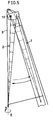
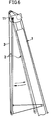
- Fig. 5 showing a conventional jib side-folding type crane which holds a folded jib 2 having a left and a right beams (the terms “left” and “right” will be hereinafter defined as direction as viewed from an operator cab under the stretched position of the jib) on one lateral side of a telescopic boom 1 with the left and the right beams vertically aligned (upright posture,) the jib 2 can be stretched through the following three steps:
- the jib 2 can be returned from its stretched position to its folded position along the one side surface of the boom 1 in the reverse order of the above.
- a jib down-folding type crane which holds a folded jib 2 having a left and a right beams on a lower surface of a telescopic boom 1 with the left and the right beams horizontally arranged (horizontal posture)6, the jib 2 can be stretched out through the following two steps:
- the jib 2 can be returned from its stretched position to its folded position along the lower surface of the boom 1 in the reverse order of the above.
- steps commonly required in both the jib side-folding type crane and the jib down-folding type crane there are the jib swinging-down step in which the jib 2 is moved from its folded position to its vertically suspended position in the stretching operation, and the jib hauling step in which the jib 2 is hauled from its vertically suspended position to its folded position.
- an auxiliary hoist wire robe (hereinafter referred to merely as a rope) 3 drawn out from an unillustrated winch provided on a crane main body in the following manner.
- the rope 3 is reeved from the forward end portion of the boom 1 through the forward end portion of the jib 2 to the base portion of the boom 1.
- the rope 3 may be reeved back from the base portion of the boom 1 to the forward end portion of the jib 2.
- the jib 2 can be swung down away from the base portion of the boom 1 or hauled thereto by unwinding or winding the rope 3.
- a jib stretching and folding device for use in a crane including a telescopic boom having a forward end portion, a jib having a base end portion, the base end of the jib being connected to a forward end portion of the boom, the jib being movable between a stretched position where the jib is stretched out from the forward end portion of the boom and a folded position along either one side surface or a lower surface of the boom through an intermediate step of putting the jib into a vertically suspended position about a connection point of the base end portion of the jib and the forward end portion of the boom;
- the jib stretching and folding device comprising:
- the jib maneuvering cylinder is actuated to extend with the jib being in the vertically suspended position.
- the engaging portion provided at the extendible actuating member and the engaging member provided at the jib are guided along the guide surface to engage with each other.
- the jib maneuvering cylinder is actuated to contract in this state, whereby the jib can be hauled to the folded position along the side surface or the lower surface of the boom.
- the maneuvering cylinder is actuated to extend with being connected to the jib, whereby the jib can be swung down from the folded position to the vertically suspended position.
- the jib With being vertically suspended, the jib is moved in a lengthwise direction thereof by, for example, extending the boom.
- This causes the engaging member provided at the jib to automatically disengage from the engaging portion provided at the jib maneuvering cylinder.
- the fixation of the jib maneuvering cylinder and the jib is released. making it possible to proceed to a subsequent step in the jib stretching operation.
- the invention is incorporated into a jib side-folding type crane. Further, there is illustrated a single stage telescopic boom 1 constructed of a fixed boom 1a turnably mounted on a crane main body A and single stage movable boom 1b.
- a jib provided with forked jib feet 21, 21 on opposite sides of a base end thereof.
- the jib 2 has two beams.
- the beam positioned lower than the other in an upright posture when the jib 2 is folded is a main beam 2a.
- To the main beam 2a is mounted a connecting member 4 rotatably about an axis y of the connecting member 4 and slidably along an axial direction thereof.
- the connecting member 4 With the connecting member 4 rotatably connected to a jib mounting shaft 11 provided on a left side surface of the boom 1, the jib 2 is stretched out forwardly from a forward end portion of the boom 1 through the following steps, the connection point of the boom 1 and the jib 2 serving as a supporting point:
- the jib 2 can be returned from the stretched position to the folded position along the left side surface in the reverse order of the above.
- the jib 2 is fixed to the fixed boom 1a by means of a jib fixing mechanism 5.
- the jib fixing mechanism 5 comprises brackets 51, 52 respectively provided at a forward end portion of the jib 2 and at the fixed boom 1a, and a connecting pin 53 for connecting the brackets 51, 52 to each other.
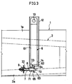
- a cylinder mounting frame 12 is secured to the left side surface of the forward end portion of the fixed boom 1a in a direction perpendicular to an axial direction of the boom 1. To the cylinder mounting frame 12 is mounted a jib maneuvering cylinder 6.
- the jib maneuvering cylinder 6 is, as enlargedly shown in Figs. 3 and 4, mounted to the mounting frame 12 in such a manner that a cylinder tube extends in a vertical direction when the boom 1 is maintained horizontally.
- a base end (an upper end in the figures) of the cylinder tube 61 is rotatably connected to the cylinder mounting frame 12 through a pin 13 extending in a widthwise direction of the boom 1.
- a rod 62 serving as an extendible actuating member projects outward of the lower surface of the boom 1.
- Indicated at 14 is a cylinder guide member fixed to the cylinder mounting frame 12.
- the rod 62 is provided with an engaging hole 64 (engaging portion ) in a forward end portion 63 thereof.
- An axis of the engaging hole 64 is perpendicular to an axis of the rod 62.
- an engaging pin 7 serving as an engaging member and disengageably insertable into the engaging hole 64.
- the engaging pin 7 is supported slidably along a line substantially parallel to the main beam 2a by pin guides 22, 23 disposed forward and rearward portions.
- the engaging pin 7 is also biased by a helical compression spring 8 in such a manner that the forward end 71 of the pin 7 facing toward the forward end of the jib 2 projects rearward from the rearward pin guide 23.
- Indicated at 9 is a stopper for regulating a rearward projection amount of the engaging pin 7.
- the forward end portion 71 of the engaging pin 7 and the forward end portion 63 of the rod 62 included in the jib maneuvering cylinder 6 are respectively provided with oblique guide surfaces 72 and 65 so as to facilitate engagement of the pin 7 and the rod 62.
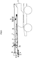
- the jib maneuvering cylinder 6 is in a contracted state when the jib 2 is in the folded position as shown in Fig. 1. In this state, the forward end portion 71 of the engaging pin 7 is inserted into the hole 64 of the cylinder 6 as shown in Fig. 3, whereby the jib maneuvering cylinder 6 and jib 2 can be engageably connected to each other.
- the jib swinging-down step from the above position and the jib hauling step in the jib folding operation are respectively carried out in the following manner.
- the connecting member 4 of the jib 2 is connected to the jib mounting shaft 11 provided on the left side surfaces of the boom 1.
- the boom 1 is pivotally moved up to a maximum angled position thereof where the angle formed between the boom 1 and the ground surface is maximum after the fixation of the jib 2 to the boom 1 by means of the jib fixing mechanism 5 is released.
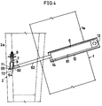
- the jib maneuvering cylinder 6 is actuated to extend by remote control from an operator's cab on the crane main body A. Thereby, the jib 2 is swung about the jib mounting shaft 11 with the connection point serving as a supporting point, consequently taking a vertically suspended position.
- the jib 2 continuously receives a rotational force toward its vertically suspended position due to the weight thereof after the fixation of the jib 2 to the boom 1 by means of the jib fixing mechanism 5 is released. Accordingly, the jib maneuvering cylinder 6 serves to render the jib 2 smoothly swing down to the vertically suspended position while suppressing the rotational force of the jib 2.
- the forward end of the jib 2 is located in a substantially high level from the ground, which deters a jib twisting operation to be executed in a subsequent step.
- the boom 1 is slightly extended so as to lift the jib 2, thereby disengaging the engaging pin 7 from the engaging hole 64. Thereafter, the boom 1 is pivotally moved downward as shown in phantom lines in Fig. 2, lowering the jib 2. In this case, the jib 2 is already in the vertically suspended position, which precludes the possibility that the jib 2 is swung in a great travel while the boom 1 is pivoted downward.
- the jib 2 can be swung down from the folded position into a position suitable for proceeding to the subsequent twisting step.
- the jib 2 can be hauled to the folded position in the folding operation in the reverse of the foregoing swing-down step. More specifically, after pivotally moving up the boom 1 from the position shown in phantom line in Fig. 2 to the maximum angled position as shown in solid lines in Fig. 2, the jib maneuvering cylinder 6 is actuated to extend.
- the forward end portion 63 of the rod 62 included in the cylinder 6 comes into contact with the forward end portion 71 of the engaging pin 7.
- the forward end portions 63, 71 are respectively guided along the guide surfaces 72, 65, and thereby the forward end portion 71 of the pin 7 is automatically inserted into the engaging hole 64 formed in the forward end portion 63 of the rod 62.
- the boom 1 is pivotally moved down to the substantially horizontal position as shown in Fig. 1.
- the jib 2 is fixed in the folded position by means of the jib fixing mechanism 5, thereby completing the jib folding operation.
- the present invention is not limited to the foregoing embodiment, but also can be embodied as follows.
- a boom is provided with a jib maneuvering cylinder and a jib is provided with an engaging member.
- the jib maneuvering cylinder includes an extendible actuating member having an engaging portion.
- the jib is made movable between a folded position and a vertically suspended position in a jib stretching operation and a jib folding operation with the engaging portion and the engaging member being engageably connected to each other by way of extension and contraction of the extendible actuating member.
- a jib stretching and folding device is used in a crane having a jib for increasing a lift of the crane, the jib being stretchable from a folded position along a side surface or a lower surface of a boom through a vertically suspended position.
- the jib stretching and folding device has a jib maneuvering cylinder, an engaging portion formed in a piston rod of the cylinder, an engaging member provided on the jib, and a guide surface formed at at least either of the engaging portion or the engaging member for guiding the engaging member so as to engage with the engaging portion.
- the jib is made movable between the vertically suspended position and the folded position by way of extension and contraction of the piston rod.
Landscapes
- Engineering & Computer Science (AREA)
- Mechanical Engineering (AREA)
- Jib Cranes (AREA)
Applications Claiming Priority (2)
| Application Number | Priority Date | Filing Date | Title |
|---|---|---|---|
| JP245069/90 | 1990-09-13 | ||
| JP2245069A JPH04125297A (ja) | 1990-09-13 | 1990-09-13 | クレーンのジブ張出し、格納装置 |
Publications (2)
| Publication Number | Publication Date |
|---|---|
| EP0476520A2 true EP0476520A2 (fr) | 1992-03-25 |
| EP0476520A3 EP0476520A3 (fr) | 1992-04-01 |
Family
ID=17128134
Family Applications (1)
| Application Number | Title | Priority Date | Filing Date |
|---|---|---|---|
| EP19910115461 Withdrawn EP0476520A3 (fr) | 1990-09-13 | 1991-09-12 | Dispositif de déployement et de repliement d'une extension de flèche d'un grue |
Country Status (4)
| Country | Link |
|---|---|
| US (1) | US5143233A (fr) |
| EP (1) | EP0476520A3 (fr) |
| JP (1) | JPH04125297A (fr) |
| KR (1) | KR950012718B1 (fr) |
Cited By (4)
| Publication number | Priority date | Publication date | Assignee | Title |
|---|---|---|---|---|
| EP1955974A1 (fr) * | 2007-02-08 | 2008-08-13 | Manitowoc Crane Companies, Inc. | Rallonge de flèche déployable automatiquement et son procédé de déploiement |
| CN103058075A (zh) * | 2012-12-26 | 2013-04-24 | 三一重工股份有限公司 | 起重机的副臂回收方法和副臂回收装置 |
| DE102012023357A1 (de) | 2012-11-22 | 2014-05-22 | Terex Cranes Germany Gmbh | Vorrichtung und Verfahren zur Positionierung und Arretierung von Ergänzungsteilen für den Kranbetrieb |
| CN107614416A (zh) * | 2015-06-05 | 2018-01-19 | 株式会社多田野 | 吊臂伸出收纳机构 |
Families Citing this family (5)
| Publication number | Priority date | Publication date | Assignee | Title |
|---|---|---|---|---|
| JP2883860B2 (ja) * | 1996-04-05 | 1999-04-19 | 株式会社小松製作所 | クレーンのジブ張出、格納装置及びその張出、格納方法 |
| JP4564622B2 (ja) * | 2000-03-27 | 2010-10-20 | 株式会社タダノ | 補助ジブ格納装置 |
| JP4227748B2 (ja) * | 2002-01-17 | 2009-02-18 | 株式会社タダノ | クレーン車のジブ格納装置 |
| JP4070473B2 (ja) * | 2002-02-08 | 2008-04-02 | 株式会社タダノ | クレーン車のジブ格納装置 |
| US7878346B1 (en) | 2008-08-25 | 2011-02-01 | Link-Belt Construction Equipment Co., L.P., Lllp | Adaptable boom extension for a mobile crane having a telescoping boom |
Family Cites Families (8)
| Publication number | Priority date | Publication date | Assignee | Title |
|---|---|---|---|---|
| US3366250A (en) * | 1966-05-11 | 1968-01-30 | Grove Mfg Co | Boom jib assembly |
| US4241837A (en) * | 1979-04-06 | 1980-12-30 | Don Suverkrop | Convertible articulated crane |
| US4491229A (en) * | 1981-02-25 | 1985-01-01 | Fmc Corporation | Boom extension stowage system |
| US4493426A (en) * | 1981-10-13 | 1985-01-15 | Kidde, Inc. | Attachment jib for cranes |
| US4621742A (en) * | 1985-01-25 | 1986-11-11 | Harnischfeger Corporation | Boom extension storage means and mechanisms |
| JPS6327396A (ja) * | 1986-07-21 | 1988-02-05 | 株式会社タダノ | 伸縮ブ−ムに継ぎ足されるジブ |
| JPH07115831B2 (ja) * | 1988-05-06 | 1995-12-13 | 株式会社神戸製鋼所 | クレーンのジブ張出し、格納装置 |
| US4953724A (en) * | 1989-06-29 | 1990-09-04 | Kabushiki Kaisha Kobe Seiko Sho | Jib stretching and folding device |
-
1990
- 1990-09-13 JP JP2245069A patent/JPH04125297A/ja active Pending
-
1991
- 1991-09-12 KR KR1019910015913A patent/KR950012718B1/ko not_active Expired - Lifetime
- 1991-09-12 US US07/758,586 patent/US5143233A/en not_active Expired - Fee Related
- 1991-09-12 EP EP19910115461 patent/EP0476520A3/fr not_active Withdrawn
Cited By (5)
| Publication number | Priority date | Publication date | Assignee | Title |
|---|---|---|---|---|
| EP1955974A1 (fr) * | 2007-02-08 | 2008-08-13 | Manitowoc Crane Companies, Inc. | Rallonge de flèche déployable automatiquement et son procédé de déploiement |
| DE102012023357A1 (de) | 2012-11-22 | 2014-05-22 | Terex Cranes Germany Gmbh | Vorrichtung und Verfahren zur Positionierung und Arretierung von Ergänzungsteilen für den Kranbetrieb |
| CN103058075A (zh) * | 2012-12-26 | 2013-04-24 | 三一重工股份有限公司 | 起重机的副臂回收方法和副臂回收装置 |
| CN107614416A (zh) * | 2015-06-05 | 2018-01-19 | 株式会社多田野 | 吊臂伸出收纳机构 |
| CN107614416B (zh) * | 2015-06-05 | 2019-11-26 | 株式会社多田野 | 吊臂伸出收纳机构 |
Also Published As
| Publication number | Publication date |
|---|---|
| KR950012718B1 (ko) | 1995-10-20 |
| US5143233A (en) | 1992-09-01 |
| EP0476520A3 (fr) | 1992-04-01 |
| KR920006222A (ko) | 1992-04-27 |
| JPH04125297A (ja) | 1992-04-24 |
Similar Documents
| Publication | Publication Date | Title |
|---|---|---|
| US4383616A (en) | Luffing jib for construction crane | |
| US4349115A (en) | Crane | |
| US4976361A (en) | Mobile crane comprising a telescopic boom | |
| US5143233A (en) | Jib stretching and folding device for use in a crane | |
| GB2081210A (en) | Method of extending a jib of a telescopic crane | |
| GB2196605A (en) | Foldable machine for handling and lifting loads | |
| US5193698A (en) | Jib stretching and folding device for use in a crane | |
| US4310098A (en) | Portable boom structure | |
| JP2000044173A (ja) | 移動式クレーンのジブ張出・格納装置 | |
| US4412622A (en) | Telescoping strut crane | |
| US4953724A (en) | Jib stretching and folding device | |
| US4473214A (en) | Luffing jib for construction crane | |
| JP3101026B2 (ja) | 補助ジブ付きクレーンのジブ張出装置 | |
| US2315873A (en) | Portable folding hoist | |
| JPS5925961Y2 (ja) | ジブブ−ム付杭打リ−ダ | |
| JP4226683B2 (ja) | ラフィングジブのバックテンション装置 | |
| JP2001040663A (ja) | 杭打機のリーダの立設方法及びその装置 | |
| US5115925A (en) | Jib stretching and folding device for crane | |
| US4050586A (en) | Apparatus for raising & lowering a mast and boom on a mobile crane | |
| JPH07157287A (ja) | クレーン | |
| JP4323854B2 (ja) | ジブ付きクレーンの安全装置 | |
| JPS6330793Y2 (fr) | ||
| RU2216462C2 (ru) | Погрузчик бортовой | |
| JPS6111196Y2 (fr) | ||
| US3716217A (en) | Trailer capable of lifting and lowering boats or the like |
Legal Events
| Date | Code | Title | Description |
|---|---|---|---|
| PUAI | Public reference made under article 153(3) epc to a published international application that has entered the european phase |
Free format text: ORIGINAL CODE: 0009012 |
|
| PUAL | Search report despatched |
Free format text: ORIGINAL CODE: 0009013 |
|
| AK | Designated contracting states |
Kind code of ref document: A2 Designated state(s): DE ES FR GB IT NL |
|
| AK | Designated contracting states |
Kind code of ref document: A3 Designated state(s): DE ES FR GB IT NL |
|
| 17P | Request for examination filed |
Effective date: 19920430 |
|
| 17Q | First examination report despatched |
Effective date: 19940607 |
|
| STAA | Information on the status of an ep patent application or granted ep patent |
Free format text: STATUS: THE APPLICATION IS DEEMED TO BE WITHDRAWN |
|
| 18D | Application deemed to be withdrawn |
Effective date: 19950110 |