EP0476402B1 - Anordnung zur Befestigung einer Handbrause - Google Patents
Anordnung zur Befestigung einer Handbrause Download PDFInfo
- Publication number
- EP0476402B1 EP0476402B1 EP91114701A EP91114701A EP0476402B1 EP 0476402 B1 EP0476402 B1 EP 0476402B1 EP 91114701 A EP91114701 A EP 91114701A EP 91114701 A EP91114701 A EP 91114701A EP 0476402 B1 EP0476402 B1 EP 0476402B1
- Authority
- EP
- European Patent Office
- Prior art keywords
- hose
- shower
- passage
- means according
- shower hose
- Prior art date
- Legal status (The legal status is an assumption and is not a legal conclusion. Google has not performed a legal analysis and makes no representation as to the accuracy of the status listed.)
- Expired - Lifetime
Links
Images


Classifications
-
- E—FIXED CONSTRUCTIONS
- E03—WATER SUPPLY; SEWERAGE
- E03C—DOMESTIC PLUMBING INSTALLATIONS FOR FRESH WATER OR WASTE WATER; SINKS
- E03C1/00—Domestic plumbing installations for fresh water or waste water; Sinks
- E03C1/02—Plumbing installations for fresh water
- E03C1/04—Water-basin installations specially adapted to wash-basins or baths
- E03C1/0401—Fixing a tap to the sanitary appliance or to an associated mounting surface, e.g. a countertop
- E03C1/0402—Fixing a tap to the sanitary appliance or to an associated mounting surface, e.g. a countertop with mounting from only one side
-
- E—FIXED CONSTRUCTIONS
- E03—WATER SUPPLY; SEWERAGE
- E03C—DOMESTIC PLUMBING INSTALLATIONS FOR FRESH WATER OR WASTE WATER; SINKS
- E03C1/00—Domestic plumbing installations for fresh water or waste water; Sinks
- E03C1/02—Plumbing installations for fresh water
- E03C1/04—Water-basin installations specially adapted to wash-basins or baths
- E03C1/0401—Fixing a tap to the sanitary appliance or to an associated mounting surface, e.g. a countertop
-
- E—FIXED CONSTRUCTIONS
- E03—WATER SUPPLY; SEWERAGE
- E03C—DOMESTIC PLUMBING INSTALLATIONS FOR FRESH WATER OR WASTE WATER; SINKS
- E03C1/00—Domestic plumbing installations for fresh water or waste water; Sinks
- E03C1/02—Plumbing installations for fresh water
- E03C1/04—Water-basin installations specially adapted to wash-basins or baths
- E03C1/0403—Connecting the supply lines to the tap body
-
- E—FIXED CONSTRUCTIONS
- E03—WATER SUPPLY; SEWERAGE
- E03C—DOMESTIC PLUMBING INSTALLATIONS FOR FRESH WATER OR WASTE WATER; SINKS
- E03C1/00—Domestic plumbing installations for fresh water or waste water; Sinks
- E03C1/02—Plumbing installations for fresh water
- E03C1/04—Water-basin installations specially adapted to wash-basins or baths
- E03C2001/0415—Water-basin installations specially adapted to wash-basins or baths having an extendable water outlet
Definitions
- the invention relates to an arrangement for fastening a hand shower, in which the shower hose is passed through an opening.
- a sanitary pool arrangement is already known (DE-PS 27 09 446), in which the water outlet fitting and the valve arrangements are arranged on a removable closure plate of an inspection opening and the connection between the fittings and the connection points is flexible Line sections are carried out.
- the closure plate is removable.
- the installation box has an outlet connected to the bathtub drain pipe in the area of its lower end.
- the water penetrating through the bushing for the shower hose can be drained off here.
- the connection to the water drainage of the bathtubs is lower than the maximum accumulation height in the tub, so that when the tub drain is opened there is a risk of dirty water being pushed back. Attaching a non-return valve to prevent a backflow does not lead to satisfactory results, since a safe working method cannot be guaranteed due to the risk of contamination.
- the invention has for its object to provide a simple and inexpensive to manufacture and assemble assembly for attaching a hand shower, in which the possibility of connecting the shower hose and thus the replacement of a shower hose is facilitated.
- the invention proposes an arrangement with the features of claim 1 and an arrangement with the features of claim 2.
- connection point of the shower hose on the pressure hose is prevented.
- the normal user does not even notice that a pressure hose is still attached to the shower hose.
- Only the installer or the knowledgeable user who wants to replace it then overcomes the lock that prevents it from being pulled out.
- the connection point can only be pulled out in a certain angular position.
- the bushing it is also possible, as the invention proposes, for the bushing to have a releasable locking element. The locking element can then be removed if the connection point is to be pulled out.
- the shower hose can be pulled out of the bushing so far that the connection point is outside the bushing. Then the assembly or replacement can be carried out particularly easily.
- the arrangement proposed by the invention is advantageous not only in the case of bathtub rim batteries or built-in washbasins, but also wherever the shower hose is passed through an opening in an element in which the rear side, i.e. the side opposite the hand shower is difficult or impossible to access.
- the corresponding end of the pressure hose can have a spring element which spreads out when pulled out and is fixed in or on the bushing by positive locking and / or non-positive locking. The hose can then slide back only when the spring element is spread back.
- the invention proposes in a further development that the shower hose between the bushing and the connection point on the pressure hose can be surrounded by a container which is watertight downwards.
- connection nipple of the shower hose can be arranged in the container. If the connection nipple then leaks, this leak does not lead to greater damage, since the water then collects in the container.
- the container can be moved completely onto the outside of the bushing. It can then be emptied there or, if necessary, also dismantled and replaced.
- the container according to the invention is formed by a solid shell which is designed to be removable from an opening.
- a possibility which is particularly preferred by the invention consists in the container being formed by a flexible hose cover which is connected in a watertight manner to the shower hose and / or the pressure hose in the region of its one end.
- tubular casing is connected in a watertight manner at both ends.
- the casing is connected to the bushing in a watertight manner in the region of its other end.
- the shower hose is below or behind the bushing along its entire length surrounded by a second protective tube, preferably at a distance, which collects the water escaping from a leak or passing through the bushing.
- tubular casing is connected to the feedthrough in such a way that unintentional pulling out of the tubular casing is prevented from the feedthrough. This can prevent the possibly existing dirty water from splashing out of the bushing when the shower hose is pulled out strongly. On the other hand, it can be achieved with this measure that the normal user does not even notice that his fitting has a special feature.
- a helical compression spring corresponding to its diameter is arranged in the tubular casing and preferably extends over the entire length of the tubular casing.
- This helical compression spring serves on the one hand to protect the hose cover or the protective hose from kinks and also has the side effect that the shower hose is drawn into the bushing with a force determined by the strength of the helical spring.
- the hose sleeve and the helical spring are pushed onto a sleeve in the respective end region and are injection-molded together in plastic. It can be both a pushing onto a sleeve from the outside and a corresponding extrusion coating from the outside, and conversely, a pushing on from the inside and extrusion coating from the inside.
- the protective tube together with the coil spring is manufactured in the factory as a single, closed and easy-to-assemble component.
- this sleeve is connected at one end to the bushing, while in the area of the other end it is possibly connected to a connecting element in the area of the connection between the two hoses.
- the invention proposes that the tubular casing be connected to a detachable connection piece of the bushing. Only after loosening the nozzle can the shower hose be pulled out so far that the protective hose and the connection point with the pressure hose reach the bushing.
- the detachable nozzle can also form the lock for pulling out the pressure hose.
- the nozzle can be removed after removing a fuse, which can be, for example, a cover rosette or a union nut.
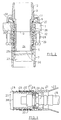
- a horizontally extending plate 1 is shown broken off.
- the plate 1 contains an opening which forms a passage 2 for the shower hose 3 of a hand shower 4, indicated by dashed lines.
- the shower hose 3 runs in a loop below the plate 1, in other words on its inside.
- the hand shower 4 is arranged above the plate 1 or on the outside of the bushing 2. If it is pulled out upwards, the hose 3 is pulled through the bushing 2.
- the bushing 2 contains a bushing element 5 which is inserted through the opening of the plate 1 from the top and which forms an outward edge 6 in the region of its top.
- the edge 6 is provided with a thread on its outside.
- the bushing element lies on the top of the plate 1 with the shoulder formed by the underside of its edge 6, possibly with the interposition of a seal. From the bottom, for example, a nut is screwed onto the outside of the lead-through element 5 and screwed against the bottom of the plate 1, so that the lead-through element 5 is then fixed.
- a funnel element 8 is then screwed onto the lower end of the lead-through element 5, which widens rounded downward.
- a nozzle 9 is inserted into the bushing element 5, which has an external thread in the region of its lower end 10.
- the nozzle contains an outwardly directed flange 11 with which it opens the top of the edge 6 of the bushing element 5 rests.
- the connecting piece 9 is designed as a soldering cone 12.
- An arcuate tube 13 is soldered to the outside of the soldering cone 12 and forms a holder for the hand shower 4.
- the nozzle 9 is fastened in that a union nut is screwed onto the external thread of the edge 6 of the lead-through element 6, which fixes the flange 11 with a shoulder. This union nut is shown in Fig. 2, to which reference will be made later.
- the shower hose 3 which is designed, for example, as a metal link hose, extends at a distance through the hollow interior of the connector 9. At its lower end remote from the hand shower 4 in FIG. 1, the shower hose 3 is connected at a connection point 14 to the end of a conventional pressure hose 15. Details of the connection of the shower hose 3 to the pressure hose 15 are not shown, since such connections are known.
- the pressure hose 15 is in turn unscrewed from a fixed feed line 16, the feed line 16 having a T-piece 17 in the exemplary embodiment shown.
- a pipe 18 coming from a valve for cold water and a pipe 19 coming from another valve for warm water lead into the T-piece 17.
- the water coming from the two valves passes via the T-piece 17 through the pressure hose 15 into the shower hose 3 and from there to the hand shower 4, from which it emerges through a jet surface 20.
- the length of the pressure hose 15 is dimensioned such that the pressure hose extends from the stationary line 16 to the bushing 2, preferably a little further. This allows the connection point by pulling on the shower hose 3 14 are moved to the implementation, so that the shower hose 3 can then be detached from the pressure hose 15.
- a connecting element 21 is arranged, which has four resilient lugs 22 spread outwards. The spreading takes place in a direction leading from the bushing 2 to the stationary supply line 16.
- the shower hose 3 is surrounded in its entire area between the bushing 2 and the connection point 14 on the pressure hose 15 by a protective hose 23 which is only partially shown.
- This tubular sleeve 23 contains in the area of its two ends a sleeve 24 with which it is connected in a watertight manner.
- the hose sleeve 23 is connected in a watertight manner to the connecting element 22 of the pressure hose 15 with the aid of the sleeve 24.
- the tubular sleeve 23 is connected in a watertight manner to the bushing 2, in the example shown to the bushing element 5, by means of its sleeve 24. This is done in that the sleeve 24 has an internal thread on its inside, with which it is screwed onto the external thread of the connector 9 with the interposition of a seal.
- the shower hose 3 is surrounded in the area under the plate 1 up to its connection to the pressure hose 15 by a container formed by the protective cover 23, which is watertight at the bottom.
- the only opening is the inside of the sleeve 24, which is only open at the top. If with the shower handle 4 removed water through the arch 13 and the implementation 2 gets into the tubular casing 23, so that the water cannot drain anywhere, but can be emptied again from the top.
- the tubular casing 23 has on its inside a helical compression spring 25 which extends over the entire length of the tubular casing 23 and is only indicated in FIG. 1, the diameter of which is somewhat larger than the diameter of the tubular casing 23.
- the helical compression spring prevents kinks in the tubular casing 23 and also in the shower hose 3 arranged at a distance in it and at the same time pulls the shower hose 3 down through the bushing 2.
- the bushing element 5 is inserted through the opening 26 of the plate 1. Between the bottom of its edge 6 and the top of the plate 1, a sealing element 27 is inserted, which has an annular shape.
- a clamping nut 28 is screwed onto the external thread of the lead-through element 5 until it is at a short distance from the underside of the plate 1.
- Two screws 29 are screwed through the clamping nut 28 and their ends press on a ring 30 which is placed around the opening 26. By tightening the screw 29, the bushing element 5 is clamped to the plate 1.
- the sleeve 24 is screwed with its internal thread arranged at its outer end onto the external thread of the connector 9.
- a seal 31 is inserted between an axial shoulder of the connecting piece 9 and an end face of the sleeve 24.
- the seal 31 is also on the inside of the bushing element 5. The sleeve 24 is thus sealed in a watertight manner with respect to the connecting piece 9 and the bushing element 5.
- the end of the helical compression spring 25 and the end of the tubular sleeve 23 are pushed onto the outside of the sleeve 24, this pushed-on end being surrounded by a plastic encapsulation 32.
- This plastic encapsulation has of course been manufactured in a factory before assembly.
- the protective tube 23 provided with the plastic sleeve 24 and the helical spring 25 is screwed onto the connecting piece 9 with the seal 31 being interposed.
- the nozzle 9 lies with the underside of its flange 11 on the top of the edge 6 of the bushing element 5. It can be secured against rotation by a pin engaging in an opening of the edge 6, but this is not necessary.
- the socket 9 is fixed by a union nut 33, which is screwed into the external thread of the edge 6 of the lead-through element 5 with a thread arranged on its inside.
- the union nut 33 defines the flange 11 with a shoulder pointing downwards.
- FIG. 3. 3 shows the connection point 14 between the shower hose 3 and the pressure hose 15.
- the end of the shower hose contains a conventional connection nipple 33 which is screwed to the usual connection nipple 34 of the pressure hose 15.
- a ring element 36 is inserted with the interposition of a seal 35, which is clamped between an end face of the sleeve 24 of the protective tube 23 and an end face of the connecting element 21.
- the sleeve 24 is screwed onto the connecting element 21.
- the ring element 36 also contains a seal 37 on its outside. The seals serve to seal the end of the sleeve 24 to the outside.
- the connecting element 21, which is connected to the end of the pressure hose 15, contains a spring element containing four resilient arms 22.
- the hand shower assumes the position shown in FIG. 1. If a user now wants to use the hand shower 4, he can remove it from the pipe 13 and pull the shower hose out of the bushing 2 and take a shower.
- the shower hose 3 can be pulled out against the action of the spring 25 at most until either the spring windings lie on the block or the end edges 38 of the sleeves 24, which are directed away from the free ends of the protective hose 23, touch each other. It is then not possible to pull it out further.
- the union nut 33 is loosened. This can be done from the top of the plate 1. Then the connector 9 with the attached upper end of the tubular sleeve 23 can be pulled up. If you pull the shower hose 3 at the same time, the opposite end of the hose cover 23 is also pulled out. Since both ends of the tubular sleeve 23 are identical, at least in their outer diameter, preferably even completely identical, the sleeve 24 with its plastic encapsulation 32 can also be pulled out through the lead-through element 5 at the opposite end of the protective tube 23.
- the spring arms 22 of the connecting element become 21 pivoted inward, and the end of the pressure hose 15 can be pulled up through the lead-through element 5.
- the protective tube 23 can be detached from the connecting element by engaging the sleeve 24.
- Fig. 4 shows a second embodiment of the arrangement proposed by the invention for fastening a hand shower.
- the container which surrounds the shower hose 3 below the plate 1
- the container is formed by a flexible hose 23, in the embodiment according to FIG. 4 it is formed by a rigid container 40.
- the rigid container 40 is inserted through an opening in the plate 1 and closed on the outside by a cover plate 41.
- a passage 42 for the shower hose which is only indicated, is arranged.
- the container 40 is sealed watertight in the region of its lower end by an end plate 44 provided with a groove 43 for receiving a seal.
- the pressure hose 15 is screwed with its nipple 34 into an axially continuous opening, at the other end of which the shower hose 3 is screwed with its nipple 33 onto the top of the plate 44.
- the water possibly passing through the passage 42 of the shower hose 3 can be collected in the container 40. It can also be pushed up so that access is possible.
- the end plate 44 is designed in a different way, ie without a radial protrusion, the container 40 can also be completely removed from the plate 1 upwards, so that access to the connection nipple 34 of the pressure hose 15 is then possible. In the illustrated embodiment, the container 40 can be pulled up from the end plate 44, so that there is also access to the connection nipple 33 of the shower hose 3.
- a shower hose can be used, which in the relaxed state has the shape of a coil spring.
- Such preformed shower hoses are known.
Landscapes
- Health & Medical Sciences (AREA)
- Life Sciences & Earth Sciences (AREA)
- Engineering & Computer Science (AREA)
- Hydrology & Water Resources (AREA)
- Public Health (AREA)
- Water Supply & Treatment (AREA)
- Bathtubs, Showers, And Their Attachments (AREA)
- Domestic Plumbing Installations (AREA)
- Massaging Devices (AREA)
- Catching Or Destruction (AREA)
- Soil Working Implements (AREA)
- Containers And Packaging Bodies Having A Special Means To Remove Contents (AREA)
- Battery Mounting, Suspending (AREA)
Applications Claiming Priority (2)
| Application Number | Priority Date | Filing Date | Title |
|---|---|---|---|
| DE4029792A DE4029792A1 (de) | 1990-09-20 | 1990-09-20 | Anordnung zur befestigung einer handbrause |
| DE4029792 | 1990-09-20 |
Publications (3)
| Publication Number | Publication Date |
|---|---|
| EP0476402A2 EP0476402A2 (de) | 1992-03-25 |
| EP0476402A3 EP0476402A3 (en) | 1992-07-01 |
| EP0476402B1 true EP0476402B1 (de) | 1995-10-25 |
Family
ID=6414618
Family Applications (1)
| Application Number | Title | Priority Date | Filing Date |
|---|---|---|---|
| EP91114701A Expired - Lifetime EP0476402B1 (de) | 1990-09-20 | 1991-08-31 | Anordnung zur Befestigung einer Handbrause |
Country Status (7)
| Country | Link |
|---|---|
| US (1) | US5277454A (da) |
| EP (1) | EP0476402B1 (da) |
| JP (1) | JP3147241B2 (da) |
| AT (1) | ATE129538T1 (da) |
| DE (2) | DE4029792A1 (da) |
| DK (1) | DK0476402T3 (da) |
| ES (1) | ES2078404T3 (da) |
Families Citing this family (21)
| Publication number | Priority date | Publication date | Assignee | Title |
|---|---|---|---|---|
| DE4103851C2 (de) * | 1991-02-08 | 1996-05-15 | Hansa Metallwerke Ag | Einrichtung zur Montage einer Wannenbatterie in einer Einbaunische zwischen der Seitenwand einer Badewanne und einer Mauer des Badezimmers oder dergleichen |
| DE59208438D1 (de) * | 1991-07-05 | 1997-06-05 | Ideal Standard | Putzschablone für eine unterputzarmatur |
| WO1993019255A1 (de) * | 1992-03-17 | 1993-09-30 | Ideal-Standard Gmbh | Wasserarmatur mit schlauch- und brausekopfhalterung |
| DE4225166A1 (de) * | 1992-07-30 | 1994-02-03 | Grohe Kg Hans | Sanitäre Mischarmatur |
| DE4440904A1 (de) * | 1994-11-17 | 1996-05-23 | Blanco Gmbh & Co Kg | Mischbatterie-Wasserauslaufeinrichtung |
| DE19808814A1 (de) * | 1998-03-03 | 1999-09-09 | Grohe Kg Hans | Sanitäre Armatur |
| DE19960739A1 (de) * | 1998-12-16 | 2000-08-03 | Correcta Gmbh | Aufnahmekasten für eine Auszieharmatur an einer Badewanne |
| DE10001490A1 (de) * | 2000-01-14 | 2001-08-23 | Meloh Armaturen Ruppel & Meloh | Verfahren zum Auswechseln eines Verbindungsschlauches einer Armaturenbaugruppe sowie Armaturenbaugruppe |
| DE10110379C1 (de) * | 2001-03-03 | 2002-05-23 | Hansa Metallwerke Ag | Einrichtung zur Montage einer Ausziehbrause an einer Trägerplatte |
| US7004410B2 (en) * | 2003-08-13 | 2006-02-28 | Jing Mei Industrial Holding Limited | Shower head |
| DE10361580A1 (de) | 2003-12-23 | 2005-07-21 | Mann + Hummel Gmbh | Keramisches Hohlfaser-Membranmodul |
| ITTO20060156A1 (it) * | 2006-03-02 | 2007-09-03 | Novecentoundici Engineering | Dispositivo per la raccolta dell'acqua dalla superficie esterna di un tubo flessibile estraibile associato ad un apparecchio sanitario |
| US7717362B2 (en) * | 2006-03-06 | 2010-05-18 | Brasstech, Inc. | Pull-down spray head with metal shell |
| DE102006041945A1 (de) * | 2006-08-29 | 2008-03-06 | Hansgrohe Ag | Brauseanordnung |
| NL2002303C2 (nl) | 2008-12-08 | 2010-06-10 | Henri Peteri Beheer Bv | Leidingconstructie voor een heetwaterkraan, alsmede een dergelijke kraan. |
| US20100175763A1 (en) * | 2009-01-15 | 2010-07-15 | Shmuel Dovid Newman | Compressed Gas Regulator Apparatus |
| AT509653B1 (de) | 2010-04-14 | 2012-04-15 | Fiereder Simone | Vorrichtung zur befestigung einer armatur |
| DE102012205417A1 (de) | 2012-04-03 | 2013-10-10 | Hansgrohe Se | Sanitärarmatur |
| CN108290702B (zh) * | 2015-10-01 | 2019-11-05 | As 美国股份有限公司 | 拉出式龙头软管缩回系统和方法 |
| US10555643B1 (en) * | 2018-10-01 | 2020-02-11 | Xiamen EASO Co., Ltd. | Humanized control device applied to health shower device |
| US10561281B1 (en) * | 2018-10-01 | 2020-02-18 | Xiamen EASO Co., Ltd. | Convenient control device applied to energy-saving shower device |
Family Cites Families (6)
| Publication number | Priority date | Publication date | Assignee | Title |
|---|---|---|---|---|
| DE1955776B2 (de) * | 1969-11-06 | 1973-03-15 | Mischwasserzulauf fuer bidets | |
| US3680780A (en) * | 1971-02-23 | 1972-08-01 | Crosweller & Co Ltd W | Ablutionary appliances |
| DE2709446C3 (de) * | 1977-03-04 | 1980-09-11 | Fa. Aloys F. Dornbracht, 5860 Iserlohn | Sanitärbecken-Anordnung |
| DE3634738C1 (en) * | 1986-10-11 | 1988-04-07 | Hansa Metallwerke Ag | Device for mounting a hand shower attachment on the side of a bath |
| DE3721152A1 (de) * | 1987-06-26 | 1989-01-05 | Grohe Armaturen Friedrich | Wasserauslaufarmatur |
| DE3840721A1 (de) * | 1988-12-02 | 1990-06-07 | Wildfang Dieter Kg | Sanitaerschlauch und verfahren zum herstellen eines sanitaerschlauches |
-
1990
- 1990-09-20 DE DE4029792A patent/DE4029792A1/de not_active Withdrawn
-
1991
- 1991-08-31 DK DK91114701.5T patent/DK0476402T3/da active
- 1991-08-31 DE DE59106762T patent/DE59106762D1/de not_active Expired - Lifetime
- 1991-08-31 AT AT91114701T patent/ATE129538T1/de not_active IP Right Cessation
- 1991-08-31 EP EP91114701A patent/EP0476402B1/de not_active Expired - Lifetime
- 1991-08-31 ES ES91114701T patent/ES2078404T3/es not_active Expired - Lifetime
- 1991-09-18 US US07/762,854 patent/US5277454A/en not_active Expired - Lifetime
- 1991-09-19 JP JP26690791A patent/JP3147241B2/ja not_active Expired - Fee Related
Also Published As
| Publication number | Publication date |
|---|---|
| ES2078404T3 (es) | 1995-12-16 |
| DK0476402T3 (da) | 1996-02-19 |
| JPH04297631A (ja) | 1992-10-21 |
| EP0476402A2 (de) | 1992-03-25 |
| US5277454A (en) | 1994-01-11 |
| DE59106762D1 (de) | 1995-11-30 |
| ATE129538T1 (de) | 1995-11-15 |
| EP0476402A3 (en) | 1992-07-01 |
| DE4029792A1 (de) | 1992-03-26 |
| JP3147241B2 (ja) | 2001-03-19 |
Similar Documents
| Publication | Publication Date | Title |
|---|---|---|
| EP0476402A2 (de) | Anordnung zur Befestigung einer Handbrause | |
| EP2025820B1 (de) | Sanitäre Funktionseinheit zum Einsetzen in eine Flüssigkeitsführung | |
| EP0787864B1 (de) | Sanitäre Sicherungseinrichtung | |
| DE202013103517U1 (de) | Befestigungsanordnung für einen Wasserhahn | |
| EP2685012A1 (de) | Wanitärarmatur mit verschwenkbarem Auslauf | |
| DE19744040A1 (de) | Ventileinrichtung | |
| DE102007009409B4 (de) | Armatur mit Schwenkauslauf | |
| EP1004712B1 (de) | Abdeck-Rosette für den Anschlussbereich einer sanitären Wandarmatur | |
| EP0538197B1 (de) | Einrichtung als Verbindung zwischen einer flexiblen unter Putz verlegten Rohrleitung und einer über Putz anzuordnenden Armatur (flexibler Dosenhals) | |
| DE202017107759U1 (de) | Sicherungsarmatur | |
| EP0804970B1 (de) | Handspritzpistole für ein Hochdruckreinigungsgerät | |
| EP0081048B1 (de) | Ab- und Überlaufgarnitur für einen Waschtisch, Bidet oder dergl. sanitären Apparat | |
| DE20002216U1 (de) | Anschluss eines Ablaufrohrs an einen Überputzspülkasten der Toilette | |
| AT4691U1 (de) | Zu- und ablaufgarnitur für bade- oder duschwannen | |
| DE202019104886U1 (de) | Hydrant | |
| DE9017255U1 (de) | Wasserkasten mit einer Ablaßschraube | |
| EP1388618B1 (de) | Ablaufgarnitur | |
| EP0499886B1 (de) | Sanitäre Wandarmatur | |
| DE4038418C2 (de) | Unterputzkasten für eine Sanitärarmatur | |
| DE4244741C2 (de) | Montagevorrichtung für eine Schutzbuchse zur Vermeidung von Inkrustationen im Bereich einer durch eine Anbohrarmatur hergestellten Bohrung | |
| DE3144893A1 (de) | Haltevorrichtung fuer eine handbrause | |
| DE3604932A1 (de) | Mehrfachanschluss-armatur fuer eine anschlussdose fuer brauchwasser-installationen | |
| DE19719217C2 (de) | Reinigungsverschluß für Entwässerungsleitungen | |
| EP0691438A2 (de) | Badewannenarmatur | |
| EP1036972A2 (de) | Anordnung zum Anschliessen einer Armatur |
Legal Events
| Date | Code | Title | Description |
|---|---|---|---|
| PUAI | Public reference made under article 153(3) epc to a published international application that has entered the european phase |
Free format text: ORIGINAL CODE: 0009012 |
|
| AK | Designated contracting states |
Kind code of ref document: A2 Designated state(s): AT BE CH DE DK ES FR GB GR IT LI LU NL SE |
|
| PUAL | Search report despatched |
Free format text: ORIGINAL CODE: 0009013 |
|
| AK | Designated contracting states |
Kind code of ref document: A3 Designated state(s): AT BE CH DE DK ES FR GB GR IT LI LU NL SE |
|
| 17P | Request for examination filed |
Effective date: 19920625 |
|
| 17Q | First examination report despatched |
Effective date: 19931105 |
|
| GRAA | (expected) grant |
Free format text: ORIGINAL CODE: 0009210 |
|
| AK | Designated contracting states |
Kind code of ref document: B1 Designated state(s): AT BE CH DE DK ES FR GB GR IT LI LU NL SE |
|
| PG25 | Lapsed in a contracting state [announced via postgrant information from national office to epo] |
Ref country code: GR Free format text: LAPSE BECAUSE OF FAILURE TO SUBMIT A TRANSLATION OF THE DESCRIPTION OR TO PAY THE FEE WITHIN THE PRESCRIBED TIME-LIMIT Effective date: 19951025 |
|
| REF | Corresponds to: |
Ref document number: 129538 Country of ref document: AT Date of ref document: 19951115 Kind code of ref document: T |
|
| REF | Corresponds to: |
Ref document number: 59106762 Country of ref document: DE Date of ref document: 19951130 |
|
| ET | Fr: translation filed | ||
| REG | Reference to a national code |
Ref country code: ES Ref legal event code: FG2A Ref document number: 2078404 Country of ref document: ES Kind code of ref document: T3 |
|
| REG | Reference to a national code |
Ref country code: CH Ref legal event code: NV Representative=s name: TROESCH SCHEIDEGGER WERNER AG |
|
| GBT | Gb: translation of ep patent filed (gb section 77(6)(a)/1977) |
Effective date: 19951216 |
|
| ITF | It: translation for a ep patent filed | ||
| REG | Reference to a national code |
Ref country code: DK Ref legal event code: T3 |
|
| PLBE | No opposition filed within time limit |
Free format text: ORIGINAL CODE: 0009261 |
|
| STAA | Information on the status of an ep patent application or granted ep patent |
Free format text: STATUS: NO OPPOSITION FILED WITHIN TIME LIMIT |
|
| PG25 | Lapsed in a contracting state [announced via postgrant information from national office to epo] |
Ref country code: LU Free format text: LAPSE BECAUSE OF NON-PAYMENT OF DUE FEES Effective date: 19960831 |
|
| PG25 | Lapsed in a contracting state [announced via postgrant information from national office to epo] |
Ref country code: SE Effective date: 19960901 |
|
| 26N | No opposition filed | ||
| EUG | Se: european patent has lapsed |
Ref document number: 91114701.5 |
|
| PGFP | Annual fee paid to national office [announced via postgrant information from national office to epo] |
Ref country code: BE Payment date: 20000824 Year of fee payment: 10 |
|
| PG25 | Lapsed in a contracting state [announced via postgrant information from national office to epo] |
Ref country code: BE Free format text: LAPSE BECAUSE OF NON-PAYMENT OF DUE FEES Effective date: 20010831 |
|
| REG | Reference to a national code |
Ref country code: GB Ref legal event code: IF02 |
|
| BERE | Be: lapsed |
Owner name: HANS GROHE G.M.B.H. & CO. K.G. Effective date: 20010831 |
|
| PGFP | Annual fee paid to national office [announced via postgrant information from national office to epo] |
Ref country code: AT Payment date: 20070822 Year of fee payment: 17 |
|
| PGFP | Annual fee paid to national office [announced via postgrant information from national office to epo] |
Ref country code: NL Payment date: 20070820 Year of fee payment: 17 |
|
| PGFP | Annual fee paid to national office [announced via postgrant information from national office to epo] |
Ref country code: ES Payment date: 20080828 Year of fee payment: 18 Ref country code: DK Payment date: 20080822 Year of fee payment: 18 Ref country code: CH Payment date: 20080825 Year of fee payment: 18 |
|
| PGFP | Annual fee paid to national office [announced via postgrant information from national office to epo] |
Ref country code: IT Payment date: 20080826 Year of fee payment: 18 Ref country code: FR Payment date: 20080818 Year of fee payment: 18 |
|
| PGFP | Annual fee paid to national office [announced via postgrant information from national office to epo] |
Ref country code: GB Payment date: 20080822 Year of fee payment: 18 |
|
| PG25 | Lapsed in a contracting state [announced via postgrant information from national office to epo] |
Ref country code: AT Free format text: LAPSE BECAUSE OF NON-PAYMENT OF DUE FEES Effective date: 20080831 |
|
| NLV4 | Nl: lapsed or anulled due to non-payment of the annual fee |
Effective date: 20090301 |
|
| PG25 | Lapsed in a contracting state [announced via postgrant information from national office to epo] |
Ref country code: NL Free format text: LAPSE BECAUSE OF NON-PAYMENT OF DUE FEES Effective date: 20090301 |
|
| PGFP | Annual fee paid to national office [announced via postgrant information from national office to epo] |
Ref country code: DE Payment date: 20090813 Year of fee payment: 19 |
|
| REG | Reference to a national code |
Ref country code: CH Ref legal event code: PL |
|
| REG | Reference to a national code |
Ref country code: DK Ref legal event code: EBP |
|
| GBPC | Gb: european patent ceased through non-payment of renewal fee |
Effective date: 20090831 |
|
| PG25 | Lapsed in a contracting state [announced via postgrant information from national office to epo] |
Ref country code: LI Free format text: LAPSE BECAUSE OF NON-PAYMENT OF DUE FEES Effective date: 20090831 Ref country code: CH Free format text: LAPSE BECAUSE OF NON-PAYMENT OF DUE FEES Effective date: 20090831 |
|
| REG | Reference to a national code |
Ref country code: FR Ref legal event code: ST Effective date: 20100430 |
|
| PG25 | Lapsed in a contracting state [announced via postgrant information from national office to epo] |
Ref country code: FR Free format text: LAPSE BECAUSE OF NON-PAYMENT OF DUE FEES Effective date: 20090831 Ref country code: DK Free format text: LAPSE BECAUSE OF NON-PAYMENT OF DUE FEES Effective date: 20090831 |
|
| REG | Reference to a national code |
Ref country code: ES Ref legal event code: FD2A Effective date: 20090901 |
|
| PG25 | Lapsed in a contracting state [announced via postgrant information from national office to epo] |
Ref country code: GB Free format text: LAPSE BECAUSE OF NON-PAYMENT OF DUE FEES Effective date: 20090831 |
|
| PG25 | Lapsed in a contracting state [announced via postgrant information from national office to epo] |
Ref country code: IT Free format text: LAPSE BECAUSE OF NON-PAYMENT OF DUE FEES Effective date: 20090831 |
|
| REG | Reference to a national code |
Ref country code: DE Ref legal event code: R119 Ref document number: 59106762 Country of ref document: DE Effective date: 20110301 |
|
| PG25 | Lapsed in a contracting state [announced via postgrant information from national office to epo] |
Ref country code: DE Free format text: LAPSE BECAUSE OF NON-PAYMENT OF DUE FEES Effective date: 20110301 |
|
| PG25 | Lapsed in a contracting state [announced via postgrant information from national office to epo] |
Ref country code: ES Free format text: LAPSE BECAUSE OF NON-PAYMENT OF DUE FEES Effective date: 20090901 |