EP0476082B1 - Dispositif pour ameliorer la reproduction des graves dans des systemes de haut-parleurs a enceintes fermees - Google Patents
Dispositif pour ameliorer la reproduction des graves dans des systemes de haut-parleurs a enceintes fermees Download PDFInfo
- Publication number
- EP0476082B1 EP0476082B1 EP91905477A EP91905477A EP0476082B1 EP 0476082 B1 EP0476082 B1 EP 0476082B1 EP 91905477 A EP91905477 A EP 91905477A EP 91905477 A EP91905477 A EP 91905477A EP 0476082 B1 EP0476082 B1 EP 0476082B1
- Authority
- EP
- European Patent Office
- Prior art keywords
- pressure
- gas
- wall
- controller
- housing
- Prior art date
- Legal status (The legal status is an assumption and is not a legal conclusion. Google has not performed a legal analysis and makes no representation as to the accuracy of the status listed.)
- Expired - Lifetime
Links
- 230000005520 electrodynamics Effects 0.000 claims abstract description 18
- 239000012528 membrane Substances 0.000 claims description 29
- 239000000463 material Substances 0.000 claims 3
- 238000013016 damping Methods 0.000 claims 1
- 239000000725 suspension Substances 0.000 claims 1
- 230000007423 decrease Effects 0.000 abstract 1
- 239000007789 gas Substances 0.000 description 16
- 230000000694 effects Effects 0.000 description 6
- 238000000034 method Methods 0.000 description 5
- 238000005192 partition Methods 0.000 description 5
- 238000012935 Averaging Methods 0.000 description 1
- 230000006835 compression Effects 0.000 description 1
- 238000007906 compression Methods 0.000 description 1
- 239000000835 fiber Substances 0.000 description 1
- 239000006260 foam Substances 0.000 description 1
- 230000001771 impaired effect Effects 0.000 description 1
- 238000004519 manufacturing process Methods 0.000 description 1
- 230000010355 oscillation Effects 0.000 description 1
- 238000011045 prefiltration Methods 0.000 description 1
- 230000005855 radiation Effects 0.000 description 1
- 230000001052 transient effect Effects 0.000 description 1
Images

Classifications
-
- H—ELECTRICITY
- H04—ELECTRIC COMMUNICATION TECHNIQUE
- H04R—LOUDSPEAKERS, MICROPHONES, GRAMOPHONE PICK-UPS OR LIKE ACOUSTIC ELECTROMECHANICAL TRANSDUCERS; DEAF-AID SETS; PUBLIC ADDRESS SYSTEMS
- H04R1/00—Details of transducers, loudspeakers or microphones
- H04R1/20—Arrangements for obtaining desired frequency or directional characteristics
- H04R1/22—Arrangements for obtaining desired frequency or directional characteristics for obtaining desired frequency characteristic only
- H04R1/28—Transducer mountings or enclosures modified by provision of mechanical or acoustic impedances, e.g. resonator, damping means
- H04R1/2807—Enclosures comprising vibrating or resonating arrangements
- H04R1/2838—Enclosures comprising vibrating or resonating arrangements of the bandpass type
- H04R1/2842—Enclosures comprising vibrating or resonating arrangements of the bandpass type for loudspeaker transducers
-
- H—ELECTRICITY
- H04—ELECTRIC COMMUNICATION TECHNIQUE
- H04R—LOUDSPEAKERS, MICROPHONES, GRAMOPHONE PICK-UPS OR LIKE ACOUSTIC ELECTROMECHANICAL TRANSDUCERS; DEAF-AID SETS; PUBLIC ADDRESS SYSTEMS
- H04R1/00—Details of transducers, loudspeakers or microphones
- H04R1/20—Arrangements for obtaining desired frequency or directional characteristics
- H04R1/22—Arrangements for obtaining desired frequency or directional characteristics for obtaining desired frequency characteristic only
- H04R1/227—Arrangements for obtaining desired frequency or directional characteristics for obtaining desired frequency characteristic only using transducers reproducing the same frequency band
-
- H—ELECTRICITY
- H04—ELECTRIC COMMUNICATION TECHNIQUE
- H04R—LOUDSPEAKERS, MICROPHONES, GRAMOPHONE PICK-UPS OR LIKE ACOUSTIC ELECTROMECHANICAL TRANSDUCERS; DEAF-AID SETS; PUBLIC ADDRESS SYSTEMS
- H04R3/00—Circuits for transducers, loudspeakers or microphones
- H04R3/002—Damping circuit arrangements for transducers, e.g. motional feedback circuits
-
- H—ELECTRICITY
- H04—ELECTRIC COMMUNICATION TECHNIQUE
- H04R—LOUDSPEAKERS, MICROPHONES, GRAMOPHONE PICK-UPS OR LIKE ACOUSTIC ELECTROMECHANICAL TRANSDUCERS; DEAF-AID SETS; PUBLIC ADDRESS SYSTEMS
- H04R1/00—Details of transducers, loudspeakers or microphones
- H04R1/20—Arrangements for obtaining desired frequency or directional characteristics
- H04R1/22—Arrangements for obtaining desired frequency or directional characteristics for obtaining desired frequency characteristic only
- H04R1/28—Transducer mountings or enclosures modified by provision of mechanical or acoustic impedances, e.g. resonator, damping means
- H04R1/2807—Enclosures comprising vibrating or resonating arrangements
- H04R1/283—Enclosures comprising vibrating or resonating arrangements using a passive diaphragm
- H04R1/2834—Enclosures comprising vibrating or resonating arrangements using a passive diaphragm for loudspeaker transducers
Definitions
- the invention relates to a device and an apparatus for supporting the reproduction of low-frequency acoustic tones, which works with a closed housing of small volume.
- the system from GOODMAN (UK application GB 2 122 051 A) is intended to remedy these disadvantageous properties: in this system, a pressure sensor arranged inside the housing measures the pressure fluctuations and drives the internal loudspeaker via an amplifier. The inner speaker is thus not electrically coupled to the outer speaker.
- the GOODMAN patent does not disclose the exact functioning of the system. It remains e.g. unclear how the pressure should be kept constant. The arrangement has a strong tendency to oscillate, and the dynamic properties of the inner transducer strongly influence the overall behavior of the system.
- the present invention builds on enquiriesenbrun's idea of an inner transducer and GOODMAN's use of an inner pressure sensor.
- the invention according to the claims enables largely unobstructed low-frequency radiation when using small loudspeaker housings and large-area loudspeakers in low-frequency loudspeaker systems, it not being necessary to influence the signals driving the loudspeakers.
- the mentioned disadvantageous properties of deep wells and GOODMANs systems are avoided.
- the object is achieved by the devices or apparatuses defined in claims 1 to 4.
- the devices are characterized in that the pressure differences between the gas pressure in the interior of the housing and the time-averaged gas pressure in the exterior of the housing caused by the deflections of the radiating loudspeaker membrane due to changes in volume of the interior volume are greatly reduced by the effect of pressure regulation. Differences in pressure between the interior and the exterior are detected by means of a gas pressure sensor and reduced by the effect of a regulation. This pressure difference is reduced by the movements of a membrane adjacent to the internal volume of an electrodynamic converter arranged inside the housing, which as a member of a Control loop works.
- the controller belonging to the control loop processes the signal that describes the pressure differences. By means of the downstream power amplifier, the controller excites the membrane of the internal electrodynamic converter to movements that greatly reduce the pressure differences that occur.
- Figure 1 shows a device according to claim 1 of the invention.
- the outdoor speaker LA is driven directly by the input signal e (t).
- the electrodynamic converter TR is integrated in a control loop, which consists of the pressure sensor P, the subtractor S, the controller R, the power amplifier A and just the electrodynamic converter TR.
- the time-averaged size of the gas pressure that prevails outside the housing G is supplied to the subtractor as the desired value.
- the duration of the averaging is long compared to the longest signal periods, e.g. 100 seconds.
- the sensor P output signal which is proportional to the gas pressure in V1, is applied to the inverting input of the subtractor.
- the controller is dimensioned so that the control deviation, and thus the pressure difference, is kept as small as possible.
- the invention according to claim 3 ensures a simple and unproblematic usability of the method by installing the apparatus in a loudspeaker housing with a loudspeaker system, which greatly weakens the effects of a finally large internal volume on the reproduction of low frequencies by using a pressure control.
- control largely unaffected by the actual housing dimensions is made possible.
- This enables the manufacture of an easy-to-use product that can also be used and used by less technically educated people.
- the simple use of a control system should be made possible, which works largely independently of the housing dimensions in the desired manner (compensation of pressure differences, no oscillation due to dead times or running times in the internal volume, no distortions due to transient processes, etc.), and also from acoustic, higher-frequency useful signal components is not excited.
- the controlled system that is to say the gas volume on which the membrane of the internal electrodynamic converter acts
- the controlled system is designed in such a way that when rapid pressure changes occur it has effectively constant and suitably defined properties.
- both goals are achieved by choosing an appropriately small partial volume V1b of the interior volume of the loudspeaker housing for the controlled system.
- This small partial volume is delimited by means of a sound-insulating wall T1 against the remaining inner volume V1a, which adjoins the membrane of the loudspeaker LA which radiates sound into the outside space.
- Another, third inner volume V2 is constructed as an approximately gas-tight chamber, which is separated from the former, small inner volume V1b by a sound-insulating wall T and the membrane M of the internal electrodynamic converter TR.
- the sound-insulating wall T1 is provided with openings D, via which the middle partial volume V1b is connected to the volume V1a.
- the breakthroughs are designed and filled with sound-absorbing fibers and foams such that sound and pressure are transmitted from the central partial volume V1b to the volume V1 and also in the opposite direction in time according to a transfer function with a low-pass characteristic.
- the gas pressure is measured in this small, medium partial volume V1b by a gas pressure sensor P arranged there.
- the instantaneous pressure differences between the gas pressure in V1b and the mean external pressure are kept negligibly small.
- the third, gas-tight chamber V2 prevents the back of the membrane M of the transducer from acting on the remaining volumes V1a, V1b or on the external volume. Since the low-pass filter transmits slow pressure changes almost unaffected, slow pressure changes are also suppressed in the internal volume V1a. Rapid pressure changes caused by the internal electrodynamic converter, however, only have an effect in the precisely defined small partial volume V1b. Dead times and the associated tendency to oscillate in the control loop can thus be easily mastered. In addition, any disturbances caused by transients in the control loop are kept away from the external loudspeaker. Another important function of the low-pass filter is that higher-frequency sound components generated by the radiating external loudspeaker LA are kept away from the control circuit (pre-filter effect).
- the apparatus according to claim 3 fulfills the task of easy and problem-free application of pressure control in loudspeaker housings. It is a mechanical unit that can be bought like a loudspeaker chassis in specialist shops and then easily integrated into one any closed housing can be installed. The control loop is already optimally adjusted, no further adjustment is necessary.
- the signal supplied to the controller which describes the deviation from the mean external pressure, is acted upon by a further signal.
- This summand is derived from the loudspeaker input signal and is proportional to it. The sign is chosen so that the inner transducer supports the movement of the membrane of the speaker.
- the setpoint signal fed to the controller which describes the time-averaged size of the gas pressure prevailing outside the loudspeaker housing, is added to a signal which is directly proportional to the input signal of the loudspeaker emitting sound into the outside space, the sign and the size of the proportionality factor being selected in this way that the gas pressure resulting from the action of the control loop in the inner volume adjacent to the membrane of the loudspeaker (LA) emitting sound exerts a force on this membrane which parallel to the input signal generated by the input driver driving the external speaker exerts on the membrane
- This loudspeaker acting driving force acts, and the effect of the spring forces resulting from the diaphragm clamping of the loudspeaker almost canceled.
- Figures 1, 2 and 3 show devices according to claims 1, 2 and 3.
- FIG. 1 The interior volume of the loudspeaker cabinet G is divided into 2 volumes V1, V2 by a gas-tight partition T.
- the external loudspeaker LA drives the input signal e (t) directly.
- the internal electrodynamic converter TR is integrated in a control loop, which consists of the pressure sensor P, the subtractor S, the controller R, the power amplifier A and the electrodynamic converter TR.
- the time-averaged size of the gas pressure that prevails outside the housing is fed to the subtractor as the setpoint.
- the output signal of the sensor P which is proportional to the gas pressure in V1, is applied to the inverting input of the subtractor.
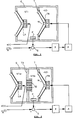
- FIG. 2 There are a cross section of the loudspeaker housing G, the outer loudspeaker LA, the inner electrodynamic converter TR with its membrane M, the second partition T1 with the openings D, the first partition T, the first volume V1a, the mean volume V1b, the last volume V2, the pressure sensor P, the subtractor S, the controller R and the amplifier A shown.
- FIG. 3 The sectional view shows the housing G with the openings D, the circumferential fastening fold F, the partition wall T, the second partition wall T1, the electrodynamic converter TR with its membrane M, the one volume V1b, the other volume V2, the pressure sensor P , the subtractor S, the controller R and the amplifier A shown.
Claims (4)
- Appareil pour la reproduction des basses fréquences par un système haut-parleur utilisant une enceinte (G) acoustique avec espace clos, dans laquelle le volume intérieur est divisé en 2 chambres (V1, V2) par une cloison (T) interne, la première chambre (V1) confinant à la membrane du haute-parleur (LA), qui émise l'ondes acoustiques vers l'extérieur de l'enceinte, dans laquelle un transducteur electrodynamique (TR), dont la mebrane mobile est déplacée par une bobine mobile en reaction avec un champ magnétique, est monté dans la cloison interne (T), de façon à ce que la membrane (M) du transducteur (TR) sépare les 2 chambres (V1, V2) internes et change avec sa motion les volumes et les pressions des deux chambres,
et dans laquelle un senseur (P) à pression du gas se trouve dans la chambre interne (V1) confinant à la membrane du haute-parleur (LA), qui émise l'ondes acoustiques vers l'extérieur de l'enceinte, le senseur producant un signal électrique, qui descrit la pression du gas dans la chambre (V1) interne, caractérisé par les faits que le senseur à pression du gas est un élément d'un circuit du régulation, que le transducteur (TR) interne est un élément de ce circuit du régulation, que ce circuit du régulation consiste de plus en un servo régulateur (R) électronique et un amplificateur (A) électronique, que le signal produit par le senseur du pression est appliqué au servo regulateur (R) comme un signal descriptif de la valeur réelle du pression du gas, que la valeur de consigne appliquée au servo regulateur est un signal descriptif de la valeur moyenne temporelle du pression du gas dans l'extérieur de l'enceinte (G), que ce regulateur (R) commande l'amplificateur de puissance qui excite le transducteur interne (TR), et que le regulateur (R) et les autres éléments du circuit sont dimensionnés de façon à ce que la difference entre la valeur momentanée du pression du gas dans la chambre (V1) interne, que confine à la membrane du haute-parleur (LA) émisant l'ondes acoustiques vers l'extérieur de l'enceinte, et la valeur moyenne temporelle du pression du gas dans l'extérieur de l'enceinte est maintenue par l'action de ce circuit du régulation presque minuscule à tout moment en comparison avec la difference du pression en operation sans regulation, tel que la valeur momentanée du pression interne et la valeur moyenne du pression extérieure sont toutes les temps quasi egales. - Appareil selon la revendication 1, caractérisé par les faits, que le volume intérieur de l'enceinte (G) acoustique avec espace clos est divisé en 3 chambres (V1a, V1b, V2) par 2 cloisons (T, T1) acoustiquement separant, de façon à ce que la première chambre (V1a) est entourée par la membrane du haute-parleur (LA), qui émise vers l'extérieur, des sections de la cloture (G) et la deuxième cloison (T1) interne, que la chambre médian (V1b) est entourée par la première cloison (T) et la deuxième cloison (T1) interne et des sections de la cloture (G), que la chambre dernière est entourée par la première cloison interne (T) et des sections de la cloture (G), que la deuxième cloison (T1) tient des percements (D), de façon à ce que les deux chambres (V1a, V1b) confinant a cette cloison (T1), c'est à dire la première chambre et la chambre médian, sont acoustiquement conjointes, que ces percements sont contruites et sont remplis avec des matérioux fibreux ou cellulaires, qui augmentent la resistance de passage, ou que toute la cloison est contruite de ces materioux, de façon à ce que la pression et le son sont transmises de la première chambre (V1a) en la chambre médian (V1b) et en arrière selon une fonction de transfert avec caractéristique filtre pass-bas, que dans une ouverture de la cloison première (T) un transducteur electrodynamique (TR) est monté , de façon à ce que sa membrane (M) sépare les 2 chambres (V1b, V2), qui confinent a cette cloison (T), c'est à dire la chambre médian et la dernière chambre, que dans la chambre médian un senseur (P) à pression du gas se trouve, que le senseur à pression du gas produce un signal électrique, qui descrit la pression du gas dans cette chambre médian, que le senseur (P) à pression du gas est un élément d'un circuit du régulation, que le transducteur (TR) électrodynamique interne monté dans la cloison première (T) est un élément de ce circuit du régulation, que ce circuit du régulation consiste de plus en un servo régulateur (R) électronique et un amplificateur (A) électronique, que le signal produit par le senseur du pression est appliqué au servo regulateur (R) comme un signal descriptif de la valeur réelle du pression du gas, que la valeur de consigne appliquée au servo regulateur est un signal descriptif de la valeur moyenne temporelle du pression du gas dans l'extérieur de l'enceinte (G), que ce regulateur (R) commande le amplificateur de puissance qui excite le transducteur interne (TR), et que le regulateur et les autres éléments du circuit sont dimensionnés de façon à ce que la difference entre la valeur momentanée du pression du gas dans la chambre médian (V1b) et la valeur moyenne temporelle du pression du gas dans l'extérieur de l'enceinte est maintenue par l'action de ce circuit du régulation presque minuscule à tout moment en comparison avec la difference du pression en operation sans regulation, tel que la valeur momentanée du pression interne et la valeur moyenne du pression extérieure sont toutes les temps quasi egales.
- Appareil pour montage dans une enceinte acoustique avec un system haut-parleur pour supporter la reproduction des basses fréquences par cette enceinte acoustique avec espaces clos caracterisé par les faits, que la cloture (G) de ce appareil est cylindrique, insonore et presque hermetique, que le volume intérieur de la cloture (G) est divisé en 2 chambres (V1b, V2) par une cloison interne (T) insonore et presque hermetique se trouvant en parallel à les deux chapeaux du cylindre, que dans une ouverture de cette cloison (T) un transducteur électrodynamique (TR) est monté , de façon à ce que sa membrane (M) sépare les 2 chambres (V1b, V2), qui confinent a cette cloison (T), que dans la chambre première (V1b) un senseur (P) à pression du gas se trouve, que ce senseur est un élément d'un circuit du régulation, que ce circuit du régulation consiste en le senseur, un servo régulateur (R) électronique, un amplificateur (A) électronique et le transducteur (TR) électrodynamique interne monté dans la cloison, que le signal électrique produit par le senseur du pression est appliqué au servo regulateur comme un signal descriptif de la valeur réelle du pression du gas, que la valeur de consigne appliquée au servo regulateur est un signal descriptif de la valeur moyenne temporelle du pression du gas dans l'extérieur de l'enceinte (G), que ce regulateur (R) commande l'amplificateur de puissance qui excite le transducteur interne (TR), que le regulateur et les autres éléments du circuit sont dimensionnés de façon à ce que la difference entre la valeur momentanée du pression du gas dans la chambre première (V1b) et la valeur moyenne temporelle du pression du gas dans l'extérieur de l'enceinte (G) est maintenue par l'action de ce circuit du régulation presque minuscule à tout moment en comparison avec la difference du pression en operation sans regulation, tel que la valeur momentanée du pression interne et la valeur moyenne du pression extérieure sont toutes les temps quasi egales, que cette première chambre est conjointe par percements dans le chapeau confinant à cette chambre avec l'extérieure, qui confine à l'enceinte en la region des percements, que les percements sont contruites et sont remplis avec des matérioux fibreux ou cellulaires insonores, de façon à ce que la pression et le son sont transmises de l'extérieure en la première chambre (V1b) et en arrière selon une fonction de transfert avec caractéristique filtre pass-bas, que la cloture cylindrique est fournie avec un pli circulaire permettant la montage hermetique du cylindre dans une ouverture propre dans la cloture de l'enceinte acoustique, que le regulateur, l'amplificateur et d'autres elements nécessaires pour l'operation se trouvent dans l'autre chambre (V2), que l'amplificateur a des transistors de sortie, qui functionent au mode commutant, et que l'appareil complet est mechaniquement une unitée.
- Appareil selon les revendications 1 et 2, caractérisé par les faits, que la valeur de consigne appliquée au servo regulateur, qui est un signal descriptif de la valeur moyenne temporelle du pression du gas dans l'extérieur de l'enceinte, est additionée avec un signal directement proportionel au signal d'attaque appliqué au haute-parleur, qui émise l'ondes acoustiques vers l'extérieur, et que le signe et la valeur du facteur de la proportionnalité sont choisies d'une manière, que la pressure du gas, qui est influencée par l'action du regulateur, dans la chambre interne confinant à la membrane du haute-parleur (LA), qui émise l'ondes acoustiques vers l'extérieur de l'enceinte, exerce sur cette membrane une force, qui agit en parallèle de la force produit par le signal d'attaque appliqué au haute-parleur de facade et influencant la membrane de ce haute-parleur, et qui quasi supprime l'effet des forces élastiques produites par la suspension de la membrane du haute-parleur.
Applications Claiming Priority (5)
| Application Number | Priority Date | Filing Date | Title |
|---|---|---|---|
| CH118790A CH680966A5 (en) | 1990-04-09 | 1990-04-09 | Bass response improving device for closed housing loudspeaker |
| CH1187/90 | 1990-04-09 | ||
| CH1991A CH681843A5 (en) | 1991-01-07 | 1991-01-07 | Bass response improving device for closed housing loudspeaker |
| CH19/91 | 1991-01-07 | ||
| PCT/CH1991/000060 WO1991015933A1 (fr) | 1990-04-09 | 1991-03-15 | Dispositif pour ameliorer la reproduction des graves dans des systemes de haut-parleurs a enceintes fermees |
Publications (2)
| Publication Number | Publication Date |
|---|---|
| EP0476082A1 EP0476082A1 (fr) | 1992-03-25 |
| EP0476082B1 true EP0476082B1 (fr) | 1996-12-11 |
Family
ID=25683270
Family Applications (1)
| Application Number | Title | Priority Date | Filing Date |
|---|---|---|---|
| EP91905477A Expired - Lifetime EP0476082B1 (fr) | 1990-04-09 | 1991-03-15 | Dispositif pour ameliorer la reproduction des graves dans des systemes de haut-parleurs a enceintes fermees |
Country Status (6)
| Country | Link |
|---|---|
| US (1) | US5461676A (fr) |
| EP (1) | EP0476082B1 (fr) |
| AT (1) | ATE146328T1 (fr) |
| CA (1) | CA2060661C (fr) |
| DE (1) | DE59108406D1 (fr) |
| WO (1) | WO1991015933A1 (fr) |
Families Citing this family (29)
| Publication number | Priority date | Publication date | Assignee | Title |
|---|---|---|---|---|
| CH684043A5 (de) * | 1991-10-05 | 1994-06-30 | Maximilian Hobelsberger | Vorrichtung zur Verbesserung der Basswiedergabe bei Lautsprechersystemen mit geschlossenen Gehäusen. |
| GB2264208B (en) * | 1992-02-15 | 1996-05-22 | Maximilian Hans Hobelsberger | A loudspeaker system |
| CH685657A5 (de) * | 1992-03-24 | 1995-08-31 | Maximilian Hobelsberger | Vorrichtung zur aktiven Simulation einer akustischen Impedanz. |
| US5812686A (en) * | 1992-03-24 | 1998-09-22 | Hobelsberger; Maximilian Hans | Device for active simultation of an acoustical impedance |
| GB9313285D0 (en) * | 1993-06-28 | 1993-08-11 | Zeneca Ltd | Acid derivatives |
| GB2297880B (en) * | 1995-01-26 | 1999-04-07 | John Ronald Watkinson | Loudspeaker |
| US5647012A (en) * | 1996-06-10 | 1997-07-08 | Han; Sang Wu | Tri-chamber speaker box |
| US6353670B1 (en) * | 1996-07-02 | 2002-03-05 | Donald R. Gasner | Actively control sound transducer |
| US6408078B1 (en) * | 1997-10-30 | 2002-06-18 | Maximilian Hobelsberger | Active reactive acoustical elements |
| US6088459A (en) * | 1997-10-30 | 2000-07-11 | Hobelsberger; Maximilian Hans | Loudspeaker system with simulated baffle for improved base reproduction |
| US6584204B1 (en) * | 1997-12-11 | 2003-06-24 | The Regents Of The University Of California | Loudspeaker system with feedback control for improved bandwidth and distortion reduction |
| US7113607B1 (en) * | 1998-09-03 | 2006-09-26 | Mullins Joe H | Low frequency feedback controlled audio system |
| CA2440926C (fr) * | 2002-09-20 | 2012-10-30 | Isao Kakuhari | Appareil de lutte anti-bruit |
| US7068806B2 (en) * | 2003-01-14 | 2006-06-27 | Walsh Casey P | Condensed speaker system |
| JP4141853B2 (ja) * | 2003-01-30 | 2008-08-27 | 三菱電機株式会社 | スピーカ |
| ITMI20041972A1 (it) * | 2004-10-18 | 2005-01-18 | Daniele Ramenzoni | Dispositivo elettroacustico, con risonatore a cavita', che fornisce caratteristiche tridimensionali estreme per controllare, concentrare e diffondere infrasuoni, suoni e ultrasuoni. |
| US20080031472A1 (en) * | 2006-08-04 | 2008-02-07 | Freeman Eric J | Electroacoustical transducing |
| US8428278B2 (en) * | 2006-08-10 | 2013-04-23 | Claudio Lastrucci | Improvements to systems for acoustic diffusion |
| KR100956552B1 (ko) * | 2008-02-27 | 2010-05-07 | 박승민 | 비주얼 스피커의 oled 및 콘페이퍼 유동 제어장치 |
| WO2010127276A1 (fr) * | 2009-05-01 | 2010-11-04 | Bose Corporation | Transduction électroacoustique à multiples éléments |
| DE102011084567C5 (de) * | 2011-10-14 | 2019-08-14 | Eberspächer Exhaust Technology GmbH & Co. KG | Aktiver Schalldämpfer |
| US9351068B2 (en) * | 2013-06-14 | 2016-05-24 | Blackberry Limited | Obstructed port audio signal alteration |
| US9432756B2 (en) | 2014-01-03 | 2016-08-30 | Blackberry Limited | Feedback enclosure and feedback system for a transducer of an electronic device |
| JP5781194B2 (ja) * | 2014-05-15 | 2015-09-16 | 株式会社オーディオテクニカ | マイクロホン |
| US9681228B2 (en) | 2014-09-30 | 2017-06-13 | Apple Inc. | Capacitive position sensing for transducers |
| US20210105556A1 (en) * | 2019-10-08 | 2021-04-08 | Soniphi Llc | Systems & Methods For Expanding Sensation Using Isobaric Chambers |
| US11172288B1 (en) * | 2020-07-14 | 2021-11-09 | Acoustic Metamaterials LLC | Methods and systems for modifying acoustics of a loudspeaker back enclosure using active noise control |
| US11721314B2 (en) * | 2020-07-14 | 2023-08-08 | Acoustic Metamaterials LLC | Methods and systems for modifying acoustics of a loudspeaker back enclosure using active noise control |
| JP6898538B1 (ja) * | 2021-03-09 | 2021-07-07 | 足立 静雄 | スピーカーシステム |
Family Cites Families (5)
| Publication number | Priority date | Publication date | Assignee | Title |
|---|---|---|---|---|
| US3867996A (en) * | 1973-11-21 | 1975-02-25 | Modular Sound Systems Inc | Speaker enclosure |
| GB1500711A (en) * | 1974-01-26 | 1978-02-08 | Tiefenbrun I | Loudspeaker systems |
| DE2637414C3 (de) * | 1976-08-19 | 1979-06-13 | Siemens Ag, 1000 Berlin Und 8000 Muenchen | AmplitudenmeBvorrichtung für die Servo-Regelung eines Lautsprechers |
| FR2405608A1 (fr) * | 1977-10-04 | 1979-05-04 | Milot Gilles | Perfectionnements aux enceintes acoustiques |
| GB2122051A (en) * | 1982-06-01 | 1984-01-04 | Goodmans Loudspeakers Limited | Loudspeaker systems |
-
1991
- 1991-03-15 EP EP91905477A patent/EP0476082B1/fr not_active Expired - Lifetime
- 1991-03-15 CA CA002060661A patent/CA2060661C/fr not_active Expired - Fee Related
- 1991-03-15 US US07/776,426 patent/US5461676A/en not_active Expired - Fee Related
- 1991-03-15 WO PCT/CH1991/000060 patent/WO1991015933A1/fr active IP Right Grant
- 1991-03-15 AT AT91905477T patent/ATE146328T1/de not_active IP Right Cessation
- 1991-03-15 DE DE59108406T patent/DE59108406D1/de not_active Expired - Fee Related
Also Published As
| Publication number | Publication date |
|---|---|
| CA2060661C (fr) | 1997-11-25 |
| CA2060661A1 (fr) | 1991-10-10 |
| US5461676A (en) | 1995-10-24 |
| WO1991015933A1 (fr) | 1991-10-17 |
| ATE146328T1 (de) | 1996-12-15 |
| EP0476082A1 (fr) | 1992-03-25 |
| DE59108406D1 (de) | 1997-01-23 |
Similar Documents
| Publication | Publication Date | Title |
|---|---|---|
| EP0476082B1 (fr) | Dispositif pour ameliorer la reproduction des graves dans des systemes de haut-parleurs a enceintes fermees | |
| AT398507B (de) | Lautsprechersystem zur wiedergabe niederfrequenter akustischer töne, das mit einem geschlossenen gehäuse kleinen volumens arbeitet | |
| US5588065A (en) | Bass reproduction speaker apparatus | |
| EP0293806B1 (fr) | Appareil d'excitation d'un haut-parleur dynamique | |
| DE102014005381B3 (de) | Anordnung und Verfahren zur Identifikation und Kompensation nichtlinearer Partialschwingungen elektromechanischer Wandler | |
| US5848169A (en) | Feedback acoustic energy dissipating device with compensator | |
| US9049501B2 (en) | Audio system with synthesized positive impedance | |
| US4052560A (en) | Loudspeaker distortion reduction systems | |
| US5206912A (en) | Power amplifier adapter | |
| US5031500A (en) | Keyboard instrument | |
| DE102010015400A1 (de) | Mikrofon für eine Hörvorrichtung sowie Verfahren zum Ermitteln eines Luftschalls und eines Körperschalls | |
| US5248846A (en) | Musical instrument incorporating a Helmholtz resonator | |
| DE102007003165A1 (de) | Flächenlautsprecher sowie Verfahren zur Einstellung des Schwingverhaltens eines Schwingsystems | |
| DE2748563A1 (de) | Lautsprecherbox | |
| DE19942526C2 (de) | MFB-Lautsprechersystem mit steuerbarer Lautsprecher-Vibrations-Charakteristik | |
| EP1169884B1 (fr) | Haut-parleur plan et son procede de production | |
| US7113607B1 (en) | Low frequency feedback controlled audio system | |
| DE10027618B4 (de) | Schallwandler | |
| EP0171065A2 (fr) | Disposition pour la contre-réaction acoustique de haut-parleurs | |
| DE2626652A1 (de) | Regelungsanordnung fuer schallsender | |
| DE2141141A1 (de) | Schaltungsanordnung zur gegenkopplung eines lautsprechers | |
| US6151396A (en) | Active acoustic resonator for abating noise | |
| DE3137747C2 (fr) | ||
| EP0435337B1 (fr) | Appareil acoustique | |
| CH681843A5 (en) | Bass response improving device for closed housing loudspeaker |
Legal Events
| Date | Code | Title | Description |
|---|---|---|---|
| PUAI | Public reference made under article 153(3) epc to a published international application that has entered the european phase |
Free format text: ORIGINAL CODE: 0009012 |
|
| 17P | Request for examination filed |
Effective date: 19911220 |
|
| AK | Designated contracting states |
Kind code of ref document: A1 Designated state(s): AT BE DE ES FR GB IT NL |
|
| 17Q | First examination report despatched |
Effective date: 19940519 |
|
| GRAG | Despatch of communication of intention to grant |
Free format text: ORIGINAL CODE: EPIDOS AGRA |
|
| GRAH | Despatch of communication of intention to grant a patent |
Free format text: ORIGINAL CODE: EPIDOS IGRA |
|
| GRAH | Despatch of communication of intention to grant a patent |
Free format text: ORIGINAL CODE: EPIDOS IGRA |
|
| GRAA | (expected) grant |
Free format text: ORIGINAL CODE: 0009210 |
|
| AK | Designated contracting states |
Kind code of ref document: B1 Designated state(s): AT BE DE ES FR GB IT NL |
|
| PG25 | Lapsed in a contracting state [announced via postgrant information from national office to epo] |
Ref country code: IT Free format text: LAPSE BECAUSE OF FAILURE TO SUBMIT A TRANSLATION OF THE DESCRIPTION OR TO PAY THE FEE WITHIN THE PRE;WARNING: LAPSES OF ITALIAN PATENTS WITH EFFECTIVE DATE BEFORE 2007 MAY HAVE OCCURRED AT ANY TIME BEFORE 2007. THE CORRECT EFFECTIVE DATE MAY BE DIFFERENT FROM THE ONE RECORDED.SCRIBED TIME-LIMIT Effective date: 19961211 Ref country code: NL Free format text: LAPSE BECAUSE OF FAILURE TO SUBMIT A TRANSLATION OF THE DESCRIPTION OR TO PAY THE FEE WITHIN THE PRESCRIBED TIME-LIMIT Effective date: 19961211 Ref country code: ES Free format text: THE PATENT HAS BEEN ANNULLED BY A DECISION OF A NATIONAL AUTHORITY Effective date: 19961211 Ref country code: FR Effective date: 19961211 |
|
| REF | Corresponds to: |
Ref document number: 146328 Country of ref document: AT Date of ref document: 19961215 Kind code of ref document: T |
|
| REF | Corresponds to: |
Ref document number: 59108406 Country of ref document: DE Date of ref document: 19970123 |
|
| PG25 | Lapsed in a contracting state [announced via postgrant information from national office to epo] |
Ref country code: BE Effective date: 19970331 |
|
| GBT | Gb: translation of ep patent filed (gb section 77(6)(a)/1977) |
Effective date: 19970307 |
|
| NLV1 | Nl: lapsed or annulled due to failure to fulfill the requirements of art. 29p and 29m of the patents act | ||
| EN | Fr: translation not filed | ||
| PLBE | No opposition filed within time limit |
Free format text: ORIGINAL CODE: 0009261 |
|
| STAA | Information on the status of an ep patent application or granted ep patent |
Free format text: STATUS: NO OPPOSITION FILED WITHIN TIME LIMIT |
|
| 26N | No opposition filed | ||
| PGFP | Annual fee paid to national office [announced via postgrant information from national office to epo] |
Ref country code: AT Payment date: 19990324 Year of fee payment: 9 |
|
| PG25 | Lapsed in a contracting state [announced via postgrant information from national office to epo] |
Ref country code: AT Free format text: LAPSE BECAUSE OF NON-PAYMENT OF DUE FEES Effective date: 20000315 |
|
| REG | Reference to a national code |
Ref country code: GB Ref legal event code: IF02 |
|
| PGFP | Annual fee paid to national office [announced via postgrant information from national office to epo] |
Ref country code: DE Payment date: 20030926 Year of fee payment: 13 |
|
| PGFP | Annual fee paid to national office [announced via postgrant information from national office to epo] |
Ref country code: GB Payment date: 20040607 Year of fee payment: 14 |
|
| PG25 | Lapsed in a contracting state [announced via postgrant information from national office to epo] |
Ref country code: DE Free format text: LAPSE BECAUSE OF NON-PAYMENT OF DUE FEES Effective date: 20041001 |
|
| PG25 | Lapsed in a contracting state [announced via postgrant information from national office to epo] |
Ref country code: GB Free format text: LAPSE BECAUSE OF NON-PAYMENT OF DUE FEES Effective date: 20050315 |
|
| GBPC | Gb: european patent ceased through non-payment of renewal fee |
Effective date: 20050315 |