EP0476082B1 - Device for improving bass reproduction in loudspeaker systems with closed housings - Google Patents
Device for improving bass reproduction in loudspeaker systems with closed housings Download PDFInfo
- Publication number
- EP0476082B1 EP0476082B1 EP91905477A EP91905477A EP0476082B1 EP 0476082 B1 EP0476082 B1 EP 0476082B1 EP 91905477 A EP91905477 A EP 91905477A EP 91905477 A EP91905477 A EP 91905477A EP 0476082 B1 EP0476082 B1 EP 0476082B1
- Authority
- EP
- European Patent Office
- Prior art keywords
- pressure
- gas
- wall
- controller
- housing
- Prior art date
- Legal status (The legal status is an assumption and is not a legal conclusion. Google has not performed a legal analysis and makes no representation as to the accuracy of the status listed.)
- Expired - Lifetime
Links
- 230000005520 electrodynamics Effects 0.000 claims abstract description 18
- 239000012528 membrane Substances 0.000 claims description 29
- 239000000463 material Substances 0.000 claims 3
- 238000013016 damping Methods 0.000 claims 1
- 239000000725 suspension Substances 0.000 claims 1
- 230000007423 decrease Effects 0.000 abstract 1
- 239000007789 gas Substances 0.000 description 16
- 230000000694 effects Effects 0.000 description 6
- 238000000034 method Methods 0.000 description 5
- 238000005192 partition Methods 0.000 description 5
- 238000012935 Averaging Methods 0.000 description 1
- 230000006835 compression Effects 0.000 description 1
- 238000007906 compression Methods 0.000 description 1
- 239000000835 fiber Substances 0.000 description 1
- 239000006260 foam Substances 0.000 description 1
- 230000001771 impaired effect Effects 0.000 description 1
- 238000004519 manufacturing process Methods 0.000 description 1
- 230000010355 oscillation Effects 0.000 description 1
- 238000011045 prefiltration Methods 0.000 description 1
- 230000005855 radiation Effects 0.000 description 1
- 230000001052 transient effect Effects 0.000 description 1
Images

Classifications
-
- H—ELECTRICITY
- H04—ELECTRIC COMMUNICATION TECHNIQUE
- H04R—LOUDSPEAKERS, MICROPHONES, GRAMOPHONE PICK-UPS OR LIKE ACOUSTIC ELECTROMECHANICAL TRANSDUCERS; DEAF-AID SETS; PUBLIC ADDRESS SYSTEMS
- H04R1/00—Details of transducers, loudspeakers or microphones
- H04R1/20—Arrangements for obtaining desired frequency or directional characteristics
- H04R1/22—Arrangements for obtaining desired frequency or directional characteristics for obtaining desired frequency characteristic only
- H04R1/28—Transducer mountings or enclosures modified by provision of mechanical or acoustic impedances, e.g. resonator, damping means
- H04R1/2807—Enclosures comprising vibrating or resonating arrangements
- H04R1/2838—Enclosures comprising vibrating or resonating arrangements of the bandpass type
- H04R1/2842—Enclosures comprising vibrating or resonating arrangements of the bandpass type for loudspeaker transducers
-
- H—ELECTRICITY
- H04—ELECTRIC COMMUNICATION TECHNIQUE
- H04R—LOUDSPEAKERS, MICROPHONES, GRAMOPHONE PICK-UPS OR LIKE ACOUSTIC ELECTROMECHANICAL TRANSDUCERS; DEAF-AID SETS; PUBLIC ADDRESS SYSTEMS
- H04R1/00—Details of transducers, loudspeakers or microphones
- H04R1/20—Arrangements for obtaining desired frequency or directional characteristics
- H04R1/22—Arrangements for obtaining desired frequency or directional characteristics for obtaining desired frequency characteristic only
- H04R1/227—Arrangements for obtaining desired frequency or directional characteristics for obtaining desired frequency characteristic only using transducers reproducing the same frequency band
-
- H—ELECTRICITY
- H04—ELECTRIC COMMUNICATION TECHNIQUE
- H04R—LOUDSPEAKERS, MICROPHONES, GRAMOPHONE PICK-UPS OR LIKE ACOUSTIC ELECTROMECHANICAL TRANSDUCERS; DEAF-AID SETS; PUBLIC ADDRESS SYSTEMS
- H04R3/00—Circuits for transducers, loudspeakers or microphones
- H04R3/002—Damping circuit arrangements for transducers, e.g. motional feedback circuits
-
- H—ELECTRICITY
- H04—ELECTRIC COMMUNICATION TECHNIQUE
- H04R—LOUDSPEAKERS, MICROPHONES, GRAMOPHONE PICK-UPS OR LIKE ACOUSTIC ELECTROMECHANICAL TRANSDUCERS; DEAF-AID SETS; PUBLIC ADDRESS SYSTEMS
- H04R1/00—Details of transducers, loudspeakers or microphones
- H04R1/20—Arrangements for obtaining desired frequency or directional characteristics
- H04R1/22—Arrangements for obtaining desired frequency or directional characteristics for obtaining desired frequency characteristic only
- H04R1/28—Transducer mountings or enclosures modified by provision of mechanical or acoustic impedances, e.g. resonator, damping means
- H04R1/2807—Enclosures comprising vibrating or resonating arrangements
- H04R1/283—Enclosures comprising vibrating or resonating arrangements using a passive diaphragm
- H04R1/2834—Enclosures comprising vibrating or resonating arrangements using a passive diaphragm for loudspeaker transducers
Definitions
- the invention relates to a device and an apparatus for supporting the reproduction of low-frequency acoustic tones, which works with a closed housing of small volume.
- the system from GOODMAN (UK application GB 2 122 051 A) is intended to remedy these disadvantageous properties: in this system, a pressure sensor arranged inside the housing measures the pressure fluctuations and drives the internal loudspeaker via an amplifier. The inner speaker is thus not electrically coupled to the outer speaker.
- the GOODMAN patent does not disclose the exact functioning of the system. It remains e.g. unclear how the pressure should be kept constant. The arrangement has a strong tendency to oscillate, and the dynamic properties of the inner transducer strongly influence the overall behavior of the system.
- the present invention builds on enquiriesenbrun's idea of an inner transducer and GOODMAN's use of an inner pressure sensor.
- the invention according to the claims enables largely unobstructed low-frequency radiation when using small loudspeaker housings and large-area loudspeakers in low-frequency loudspeaker systems, it not being necessary to influence the signals driving the loudspeakers.
- the mentioned disadvantageous properties of deep wells and GOODMANs systems are avoided.
- the object is achieved by the devices or apparatuses defined in claims 1 to 4.
- the devices are characterized in that the pressure differences between the gas pressure in the interior of the housing and the time-averaged gas pressure in the exterior of the housing caused by the deflections of the radiating loudspeaker membrane due to changes in volume of the interior volume are greatly reduced by the effect of pressure regulation. Differences in pressure between the interior and the exterior are detected by means of a gas pressure sensor and reduced by the effect of a regulation. This pressure difference is reduced by the movements of a membrane adjacent to the internal volume of an electrodynamic converter arranged inside the housing, which as a member of a Control loop works.
- the controller belonging to the control loop processes the signal that describes the pressure differences. By means of the downstream power amplifier, the controller excites the membrane of the internal electrodynamic converter to movements that greatly reduce the pressure differences that occur.
- Figure 1 shows a device according to claim 1 of the invention.
- the outdoor speaker LA is driven directly by the input signal e (t).
- the electrodynamic converter TR is integrated in a control loop, which consists of the pressure sensor P, the subtractor S, the controller R, the power amplifier A and just the electrodynamic converter TR.
- the time-averaged size of the gas pressure that prevails outside the housing G is supplied to the subtractor as the desired value.
- the duration of the averaging is long compared to the longest signal periods, e.g. 100 seconds.
- the sensor P output signal which is proportional to the gas pressure in V1, is applied to the inverting input of the subtractor.
- the controller is dimensioned so that the control deviation, and thus the pressure difference, is kept as small as possible.
- the invention according to claim 3 ensures a simple and unproblematic usability of the method by installing the apparatus in a loudspeaker housing with a loudspeaker system, which greatly weakens the effects of a finally large internal volume on the reproduction of low frequencies by using a pressure control.
- control largely unaffected by the actual housing dimensions is made possible.
- This enables the manufacture of an easy-to-use product that can also be used and used by less technically educated people.
- the simple use of a control system should be made possible, which works largely independently of the housing dimensions in the desired manner (compensation of pressure differences, no oscillation due to dead times or running times in the internal volume, no distortions due to transient processes, etc.), and also from acoustic, higher-frequency useful signal components is not excited.
- the controlled system that is to say the gas volume on which the membrane of the internal electrodynamic converter acts
- the controlled system is designed in such a way that when rapid pressure changes occur it has effectively constant and suitably defined properties.
- both goals are achieved by choosing an appropriately small partial volume V1b of the interior volume of the loudspeaker housing for the controlled system.
- This small partial volume is delimited by means of a sound-insulating wall T1 against the remaining inner volume V1a, which adjoins the membrane of the loudspeaker LA which radiates sound into the outside space.
- Another, third inner volume V2 is constructed as an approximately gas-tight chamber, which is separated from the former, small inner volume V1b by a sound-insulating wall T and the membrane M of the internal electrodynamic converter TR.
- the sound-insulating wall T1 is provided with openings D, via which the middle partial volume V1b is connected to the volume V1a.
- the breakthroughs are designed and filled with sound-absorbing fibers and foams such that sound and pressure are transmitted from the central partial volume V1b to the volume V1 and also in the opposite direction in time according to a transfer function with a low-pass characteristic.
- the gas pressure is measured in this small, medium partial volume V1b by a gas pressure sensor P arranged there.
- the instantaneous pressure differences between the gas pressure in V1b and the mean external pressure are kept negligibly small.
- the third, gas-tight chamber V2 prevents the back of the membrane M of the transducer from acting on the remaining volumes V1a, V1b or on the external volume. Since the low-pass filter transmits slow pressure changes almost unaffected, slow pressure changes are also suppressed in the internal volume V1a. Rapid pressure changes caused by the internal electrodynamic converter, however, only have an effect in the precisely defined small partial volume V1b. Dead times and the associated tendency to oscillate in the control loop can thus be easily mastered. In addition, any disturbances caused by transients in the control loop are kept away from the external loudspeaker. Another important function of the low-pass filter is that higher-frequency sound components generated by the radiating external loudspeaker LA are kept away from the control circuit (pre-filter effect).
- the apparatus according to claim 3 fulfills the task of easy and problem-free application of pressure control in loudspeaker housings. It is a mechanical unit that can be bought like a loudspeaker chassis in specialist shops and then easily integrated into one any closed housing can be installed. The control loop is already optimally adjusted, no further adjustment is necessary.
- the signal supplied to the controller which describes the deviation from the mean external pressure, is acted upon by a further signal.
- This summand is derived from the loudspeaker input signal and is proportional to it. The sign is chosen so that the inner transducer supports the movement of the membrane of the speaker.
- the setpoint signal fed to the controller which describes the time-averaged size of the gas pressure prevailing outside the loudspeaker housing, is added to a signal which is directly proportional to the input signal of the loudspeaker emitting sound into the outside space, the sign and the size of the proportionality factor being selected in this way that the gas pressure resulting from the action of the control loop in the inner volume adjacent to the membrane of the loudspeaker (LA) emitting sound exerts a force on this membrane which parallel to the input signal generated by the input driver driving the external speaker exerts on the membrane
- This loudspeaker acting driving force acts, and the effect of the spring forces resulting from the diaphragm clamping of the loudspeaker almost canceled.
- Figures 1, 2 and 3 show devices according to claims 1, 2 and 3.
- FIG. 1 The interior volume of the loudspeaker cabinet G is divided into 2 volumes V1, V2 by a gas-tight partition T.
- the external loudspeaker LA drives the input signal e (t) directly.
- the internal electrodynamic converter TR is integrated in a control loop, which consists of the pressure sensor P, the subtractor S, the controller R, the power amplifier A and the electrodynamic converter TR.
- the time-averaged size of the gas pressure that prevails outside the housing is fed to the subtractor as the setpoint.
- the output signal of the sensor P which is proportional to the gas pressure in V1, is applied to the inverting input of the subtractor.
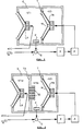
- FIG. 2 There are a cross section of the loudspeaker housing G, the outer loudspeaker LA, the inner electrodynamic converter TR with its membrane M, the second partition T1 with the openings D, the first partition T, the first volume V1a, the mean volume V1b, the last volume V2, the pressure sensor P, the subtractor S, the controller R and the amplifier A shown.
- FIG. 3 The sectional view shows the housing G with the openings D, the circumferential fastening fold F, the partition wall T, the second partition wall T1, the electrodynamic converter TR with its membrane M, the one volume V1b, the other volume V2, the pressure sensor P , the subtractor S, the controller R and the amplifier A shown.
Abstract
Description
Die Erfindung betrifft eine Vorrichtung und einen Apparat zur Unterstützung zur Wiedergabe niederfrequenter akustischer Töne, das mit einem geschlossenen Gehäuse kleinen Volumens arbeitet.The invention relates to a device and an apparatus for supporting the reproduction of low-frequency acoustic tones, which works with a closed housing of small volume.
Bei herkömmlichen Lautsprechersystemen mit akustisch geschlossenen Lautsprechergehäusen stellt sich das Problem, daß ein kleines Gehäusevolumen die Tieftonwiedergabe stark beeinträchtigt. Bei zu kleinem Gehäusevolumen beeinträchtigen Gasdruckkräfte, d.h. Kompressionskräfte, die Bewegungen der schallabstrahlenden Lautsprechermembran. Diese Druckkräfte werden dadurch hervorgerufen, daß die abstrahlende Lautsprechermembran durch ihre Auslenkung das Volumen der im Gehäuse eingeschlossenen Gase verändert, die Gase komprimiert bzw. dekomprimiert. Diese Druckkräfte wirken als Federkräfte auf die Lautsprechermembran ein und erhöhen die Resonanzfrequenz und zusätzlich die Güte des Gesamtsystems.
Um eine gute Tieftonwiedergabe zu ermöglichen, werden daher entweder unhandlich große Gehäuse verwendet, oder es werden die die Lautsprecher treibenden Signale einer Frequenzgangkorrektur unterzogen, oder es werden die abstrahlenden Lautsprechermembranen direkt in korrigierende Regelkreise eingebunden. Die beiden letzteren Maßnahmen verursachen selbst wiederum akustische Verfälschungen, insbesondere das Impulsverhalten wird durch die notwendigen Frequenzweichen beeinträchtigt.
Weiters sind Verfahren bekannt (Tiefenbrun; US-Pat. 4008374), die durch Einwirkung der Membran eines innerhalb des Gehäuses angeordnete Lautsprechers, der elektrisch parallel zum Außenlautsprecher geschaltet ist, eine wirkungsmäßige Volumsvergrößerung des Gehäuses bezwecken. Bei diesem Verfahren wird jedoch das Problem auf den innenliegenden Lautsprecher verlagert. Um befriedigende Ergebnisse zu erzielen, sind wiederum große Volumina erforderlich. Außerdem entstehen Verzerrungen durch Phasenunterschiede in den Bewegungen der beiden Membranen.In conventional loudspeaker systems with acoustically closed loudspeaker housings, the problem arises that a small housing volume greatly impairs the bass reproduction. If the housing volume is too small, gas pressure forces, ie compression forces, impair the movements of the sound-emitting loudspeaker diaphragm. These compressive forces are caused by the fact that the deflection of the radiating loudspeaker membrane changes the volume of the gases enclosed in the housing, and compresses or decompresses the gases. These compressive forces act as spring forces on the loudspeaker diaphragm and increase the resonance frequency and also the quality of the overall system.
In order to enable good bass reproduction, unwieldy housings are either used, or the signals driving the loudspeakers are subjected to a frequency response correction, or the radiating loudspeaker membranes are directly integrated into corrective control loops. The latter two measures themselves cause acoustic falsifications, in particular the impulse behavior is impaired by the necessary crossovers.
Furthermore, methods are known (Tiefenbrun; US Pat. 4008374) which, by the action of the membrane of a loudspeaker arranged inside the housing and electrically connected in parallel with the external loudspeaker, are intended to effectively increase the volume of the housing. With this method, however, the problem is shifted to the internal speaker. Again, large volumes are required to achieve satisfactory results. In addition, there are distortions due to phase differences in the movements of the two membranes.
Diesen nachteiligen Eigenschaften soll das System von GOODMAN (UK Anmeldung GB 2 122 051 A) abhelfen: In diesem System mißt ein innerhalb des Gehäuses angeordneter Drucksensor die Druckschwankungen und treibt über einen Verstärker den inneren Lautsprecher. Der innere Lautsprecher ist somit elektrisch nicht mit dem äußeren Lautsprecher gekoppelt. Die Patentschrift von GOODMAN offenbart jedoch nicht die genaue Funktionsweise des Systems. Es bleibt z.B. unklar, wie der Druck konstant gehalten werden soll. Die Anordnung weist eine starke Schwingneigung auf, und die dynamischen Eigenschaften des inneren Wandlers beeinflußen stark das Gesamtverhalten des Systems.The system from GOODMAN (UK application GB 2 122 051 A) is intended to remedy these disadvantageous properties: in this system, a pressure sensor arranged inside the housing measures the pressure fluctuations and drives the internal loudspeaker via an amplifier. The inner speaker is thus not electrically coupled to the outer speaker. However, the GOODMAN patent does not disclose the exact functioning of the system. It remains e.g. unclear how the pressure should be kept constant. The arrangement has a strong tendency to oscillate, and the dynamic properties of the inner transducer strongly influence the overall behavior of the system.
Die vorliegende Erfindung baut auf Tiefenbruns Idee eines inneren Wandlers und GOODMANS Verwendung eines inneren Drucksensors auf.The present invention builds on Tiefenbrun's idea of an inner transducer and GOODMAN's use of an inner pressure sensor.
Die Erfindung gemäß den Ansprüchen ermöglicht eine weitgehend unbehinderte Tieftonabstrahlung bei Verwendung kleiner Lautsprechergehäuse und großflächiger Lautsprecher in Tiefton-Lautsprechersystemen, wobei eine Beeinflussung der die Lautsprecher treibenden Signale nicht vorgenommen werden muß. Die genannten nachteiligen Eigenschaften von Tiefenbruns und GOODMANs Systemen werden vermieden.The invention according to the claims enables largely unobstructed low-frequency radiation when using small loudspeaker housings and large-area loudspeakers in low-frequency loudspeaker systems, it not being necessary to influence the signals driving the loudspeakers. The mentioned disadvantageous properties of deep wells and GOODMANs systems are avoided.
Die gestellte Aufgabe wird durch die Vorrichtungen, bzw. Apparate die in den Ansprüchen 1 bis 4 definiert werden, gelöst.
Die Vorrichtungen zeichnen sich dadurch aus, daß die von den Auslenkungen der abstrahlenden Lautsprechermembran durch Volumsänderungen des Innenvolumens verursachten Druckdifferenzen zwischen dem Gasdruck im Gehäuseinneren und dem zeitlich gemittelten Gasdruck im Außenraum des Gehäuses durch die Wirkung einer Druckregelung stark verringert werden.
Druckunterschiede zwischen dem Innenraum und dem Außenraum werden mittels eines Gasdrucksensors erfaßt und durch die Wirkung einer Regelung vermindert. Diese Verminderung der Druckdifferenzen erfolgt durch die Bewegungen einer an das Innenvolumen angrenzenden Membran eines innerhalb des Gehäuses angeordneten elektrodynamischen Wandlers, der als Glied eines Regelkreises arbeitet. Der zu dem Regelkreis gehörende Regler verarbeitet das Signal, das die Druckunterschiede beschreibt. Mittels des nachgeschalteten Leistungsverstärkers regt der Regler die Membran des innenliegenden elektrodynamischen Wandlers zu Bewegungen an, die die auftretenden Druckunterschiede stark verringern.The object is achieved by the devices or apparatuses defined in claims 1 to 4.
The devices are characterized in that the pressure differences between the gas pressure in the interior of the housing and the time-averaged gas pressure in the exterior of the housing caused by the deflections of the radiating loudspeaker membrane due to changes in volume of the interior volume are greatly reduced by the effect of pressure regulation.
Differences in pressure between the interior and the exterior are detected by means of a gas pressure sensor and reduced by the effect of a regulation. This pressure difference is reduced by the movements of a membrane adjacent to the internal volume of an electrodynamic converter arranged inside the housing, which as a member of a Control loop works. The controller belonging to the control loop processes the signal that describes the pressure differences. By means of the downstream power amplifier, the controller excites the membrane of the internal electrodynamic converter to movements that greatly reduce the pressure differences that occur.
Bild 1 zeigt eine Vorrichtung gemäß Anspruch 1 der Erfindung. Der Außenlautsprecher LA wird direkt durch das Eingangssignal e(t) angetrieben. Der elektrodynamische Wandler TR ist in eine Regelschleife eingebunden, die aus dem Drucksensor P, dem Subtrahierglied S, dem Regler R, dem Leistungsverstärker A und eben aus dem elektrodynamischen Wandler TR besteht. Dem Subtrahierglied wird als Sollwert die zeitlich gemittelte Größe des Gasdruckes, der außerhalb des Gehäuses G herrscht, zugeführt. Die Zeitdauer der Mittelwertsbildung ist dabei groß gegenüber den längsten Signalperioden, z.B. 100 Sekunden. Am invertierenden Eingang des Subtrahiergliedes wird das dem Gasdruck in V1 proportionale Ausgangssignal das Sensors P angelegt. Der Regler ist so bemessen, daß die Regelabweichung, und somit die Druckdifferenz, möglichst klein gehalten wird.Figure 1 shows a device according to claim 1 of the invention. The outdoor speaker LA is driven directly by the input signal e (t). The electrodynamic converter TR is integrated in a control loop, which consists of the pressure sensor P, the subtractor S, the controller R, the power amplifier A and just the electrodynamic converter TR. The time-averaged size of the gas pressure that prevails outside the housing G is supplied to the subtractor as the desired value. The duration of the averaging is long compared to the longest signal periods, e.g. 100 seconds. The sensor P output signal, which is proportional to the gas pressure in V1, is applied to the inverting input of the subtractor. The controller is dimensioned so that the control deviation, and thus the pressure difference, is kept as small as possible.
Die Erfindung gemäß Anspruch 3 gewährleistet eine einfache und unproblematische Einsetzbarkeit des Verfahrens durch Einbau des Apparates in ein Lautsprechergehäuse mit Lautsprechersystem, das durch Anwendung einer Druckregelung die Auswirkungen eines endlich großen Innenvolumens auf die Wiedergabe tiefer Frequenzen stark abschwächt.The invention according to claim 3 ensures a simple and unproblematic usability of the method by installing the apparatus in a loudspeaker housing with a loudspeaker system, which greatly weakens the effects of a finally large internal volume on the reproduction of low frequencies by using a pressure control.
Insbesondere wird ein von den tatsächlichen Gehäuseabmessungen weitgehend unbeeinflußter Einsatz der Regelung ermöglicht. Dadurch wird die Fertigung eines einfach einzusetzenden Produktes, das auch von technisch weniger gebildeten Personen angewendet und gebraucht werden kann, ermöglicht.
Es soll der einfache Einsatz einer Regelung ermöglicht werden, die weitgehend unabhängig von den Gehäuseabmessungen in erwünschter Art und und Weise arbeitet ( Ausregelung von Druckunterschieden, kein Schwingen durch Totzeiten bzw. Laufzeiten im Innenvolumen, keine Verzerrungen durch Einschwingvorgänge etc.), und die außerdem von akustischen, höherfrequenten Nutzsignalkomponenten nicht angeregt wird.In particular, use of the control largely unaffected by the actual housing dimensions is made possible. This enables the manufacture of an easy-to-use product that can also be used and used by less technically educated people.
The simple use of a control system should be made possible, which works largely independently of the housing dimensions in the desired manner (compensation of pressure differences, no oscillation due to dead times or running times in the internal volume, no distortions due to transient processes, etc.), and also from acoustic, higher-frequency useful signal components is not excited.
Die Vorrichtungen, die in den Ansprüchen 2 und 3 definiert sind, lösen obige Aufgaben.The devices defined in claims 2 and 3 achieve the above objects.
Die Lösung wird einerseits dadurch erreicht, daß die Regelstrecke, also das Gasvolumen, auf das die Membran des innenliegenden elektrodynamischen Wandlers einwirkt, so gestaltet ist, daß sie beim Auftreten schneller Druckänderungen wirkungsmäßig konstante und geeignet festgelegte Eigenschaften aufweist. Außerdem muß sichergestellt werden, daß die Regelstrecke durch höherfrequente Komponenten des von dem abstrahlenden Lautsprecher erzeugten akustischen Signales nicht beeinflußt wird.
Beide Ziele werden gemäß Bild 2 erreicht, indem für die Regelstrecke ein angemessen kleines Teilvolumen V1b des Innenvolumens des Lautsprechergehäuses gewählt wird. Dieses kleine Teilvolumen wird mittels einer schallisolierenden Wand T1 gegen das restliche Innenvolumen V1a abgegrenzt, das an die Membran des in den Außenraum Schall abstrahlenden Lautsprechers LA angrenzt. Ein weiteres, drittes Innenvolumen V2 ist als annähernd gasdichte Kammer aufgebaut, die durch eine schallisolierende Wand T und die Membran M des innenliegenden elektrodynamischen Wandlers TR von dem ersteren, kleinen Innenvolumen V1b getrennt ist.The solution is achieved, on the one hand, in that the controlled system, that is to say the gas volume on which the membrane of the internal electrodynamic converter acts, is designed in such a way that when rapid pressure changes occur it has effectively constant and suitably defined properties. In addition, it must be ensured that the controlled system is not influenced by higher-frequency components of the acoustic signal generated by the radiating loudspeaker.
According to Figure 2, both goals are achieved by choosing an appropriately small partial volume V1b of the interior volume of the loudspeaker housing for the controlled system. This small partial volume is delimited by means of a sound-insulating wall T1 against the remaining inner volume V1a, which adjoins the membrane of the loudspeaker LA which radiates sound into the outside space. Another, third inner volume V2 is constructed as an approximately gas-tight chamber, which is separated from the former, small inner volume V1b by a sound-insulating wall T and the membrane M of the internal electrodynamic converter TR.
Die schallisolierende Wand T1 ist mit Durchbrüchen D versehen, über die das mittlere Teilvolumen V1b mit dem Volumen V1a verbunden ist. Die Durchbrüche sind derart gestaltet und so mit schalldämpfenden Faser- und Schaumstoffen ausgefüllt, daß eine Schall- und Druckübertragung von dem mittleren Teilvolumen V1b in das Volumen V1 und auch in umgekehrter Richtung zeitlich gemäß einer übertragungsfunktion mit Tiefpaßcharakteristik erfolgt. In diesem kleinen, mittleren Teilvolumen V1b wird durch einen dort angeordneten Gasdrucksensor P der Gasdruck gemessen. In
Zusammenwirkung mit einem elektronischen Regler R und einem elektrischen Leistungsverstärker A und durch Einwirkung der Membran M des elektrodynamischen Wandlers TR auf dieses Teilvolumen V1b werden die momentanen Druckdifferenzen zwischen dem Gasdruck in V1b und dem mittleren Außendruck verschwindend klein gehalten. Die dritte, gasdichte Kammer V2 verhindert dabei Einwirkungen der Rückseite der Membran M des Wandlers auf die übrigen Volumina V1a, V1b oder auf das Außenvolumen.
Da das Tiefpaßfilter langsame Druckänderungen fast unbeeinflußt überträgt, werden langsame Druckänderungen auch im Innenvolumen V1a annähernd unterdrückt. Schnelle, durch den innenliegenden elektrodynamischen Wandler verursachte Druckänderungen wirken jedoch nur in dem genau definierten kleinen Teilvolumen V1b. Totzeiten und die damit verbundene Schwingneigung des Regelkreises können so einfach beherrscht werden. Zusätzlich werden etwaige Störungen, verursacht von Einschwingvorgängen des Regelkreises, von dem Außenlautsprecher ferngehalten. Eine weitere wichtige Funktion des Tiefpassfilters besteht darin, daß höherfrequente, vom abstrahlenden Außenlautsprecher LA erzeugte Schallanteile von dem Regelkreis ferngehalten werden (Vorfilterwirkung).The sound-insulating wall T1 is provided with openings D, via which the middle partial volume V1b is connected to the volume V1a. The breakthroughs are designed and filled with sound-absorbing fibers and foams such that sound and pressure are transmitted from the central partial volume V1b to the volume V1 and also in the opposite direction in time according to a transfer function with a low-pass characteristic. The gas pressure is measured in this small, medium partial volume V1b by a gas pressure sensor P arranged there. In
In cooperation with an electronic regulator R and an electrical power amplifier A and through the action of the membrane M of the electrodynamic converter TR on this partial volume V1b, the instantaneous pressure differences between the gas pressure in V1b and the mean external pressure are kept negligibly small. The third, gas-tight chamber V2 prevents the back of the membrane M of the transducer from acting on the remaining volumes V1a, V1b or on the external volume.
Since the low-pass filter transmits slow pressure changes almost unaffected, slow pressure changes are also suppressed in the internal volume V1a. Rapid pressure changes caused by the internal electrodynamic converter, however, only have an effect in the precisely defined small partial volume V1b. Dead times and the associated tendency to oscillate in the control loop can thus be easily mastered. In addition, any disturbances caused by transients in the control loop are kept away from the external loudspeaker. Another important function of the low-pass filter is that higher-frequency sound components generated by the radiating external loudspeaker LA are kept away from the control circuit (pre-filter effect).
Der Apparat gemäß Anspruch 3 erfüllt die Aufgabe der leichten und problemlosen Anwendbarkeit der Druckregelung in Lautsprechergehäusen. Er stellt eine mechanische Einheit dar, die wie ein Lautsprecherchassis im Fachhandel gekauft werden kann und danach problemlos in ein beliebiges geschlossenes Gehäuse eingebaut werden kann. Der Regelkreis ist dabei schon optimal abgeglichen, ein weiteres Einstellen erübrigt sich.The apparatus according to claim 3 fulfills the task of easy and problem-free application of pressure control in loudspeaker housings. It is a mechanical unit that can be bought like a loudspeaker chassis in specialist shops and then easily integrated into one any closed housing can be installed. The control loop is already optimally adjusted, no further adjustment is necessary.
Nach Anspruch 4 wird das dem Regler zugeführte Signal, das die Abweichung vom mittleren Außendruck beschreibt, mit einem weiteren Signal beaufschlagt. Dieser Summand ist aus dem Eingangssignal des Lautsprechers abgeleitet und diesem proportional. Das Vorzeichen wird so gewählt, daß der innere Wandler die Bewegung der Membran des Lautsprechers unterstützt.According to claim 4, the signal supplied to the controller, which describes the deviation from the mean external pressure, is acted upon by a further signal. This summand is derived from the loudspeaker input signal and is proportional to it. The sign is chosen so that the inner transducer supports the movement of the membrane of the speaker.
Das dem Regler zugeführte Sollwertsignal, das die zeitlich gemittelte Größe des außerhalb des Lautsprechergehäuses herrschenden Gasdruckes beschreibt, wird mit einem Signal addiert, das dem Eingangssignal des in den Außenraum Schall abstrahlenden Lautsprechers direkt proportional ist, wobei das Vorzeichen und die Größe des Proportionalitätsfaktors derart gewählt sind, daß der durch die Wirkung des Regelkreises sich einstellende Gasdruck in dem an die Membran des in den Außenraum Schall abstrahlenden Lautsprechers (LA) angrenzenden Innenvolumen auf diese Membran eine Kraft ausübt, die parallel zu der von dem den Außenlautsprecher treibenden Eingangssignal erzeugten, auf die Membran dieses Lautsprechers einwirkenden Antriebskraft wirkt, und die die von der Membraneinspannung des Lautsprechers herrührenden Federkräfte in ihrer wirkung annähernd aufhebt.The setpoint signal fed to the controller, which describes the time-averaged size of the gas pressure prevailing outside the loudspeaker housing, is added to a signal which is directly proportional to the input signal of the loudspeaker emitting sound into the outside space, the sign and the size of the proportionality factor being selected in this way that the gas pressure resulting from the action of the control loop in the inner volume adjacent to the membrane of the loudspeaker (LA) emitting sound exerts a force on this membrane which parallel to the input signal generated by the input driver driving the external speaker exerts on the membrane This loudspeaker acting driving force acts, and the effect of the spring forces resulting from the diaphragm clamping of the loudspeaker almost canceled.
Die Bilder 1, 2 und 3 zeigen Vorrichtungen gemäß den Ansprüchen 1, 2, und 3.Figures 1, 2 and 3 show devices according to claims 1, 2 and 3.
Bild 1 Das Innenvolumen des Lautsprechergehäuses G ist durch eine gasdichte Trennwand T in 2 Volumina V1, V2 aufgeteilt. Den Außenlautsprecher LA treibt direkt das Eingangssignal e(t). Der innenliegende elektrodynamische Wandler TR ist in eine Regelschleife eingebunden, die aus dem Drucksensor P, dem Subtrahierglied S, dem Regler R, dem Leistungsverstärker A und dem elektrodynamischen Wandler TR besteht. Dem Subtrahierglied wird als Sollwert die zeitlich gemittelte Größe des Gasdruckes, der außerhalb des Gehäuses herrscht, zugeführt. Am invertierenden Eingang des Subtrahiergliedes wird das dem Gasdruck in V1 proportionale Ausgangssignal des Sensors P angelegt. Figure 1 The interior volume of the loudspeaker cabinet G is divided into 2 volumes V1, V2 by a gas-tight partition T. The external loudspeaker LA drives the input signal e (t) directly. The internal electrodynamic converter TR is integrated in a control loop, which consists of the pressure sensor P, the subtractor S, the controller R, the power amplifier A and the electrodynamic converter TR. The time-averaged size of the gas pressure that prevails outside the housing is fed to the subtractor as the setpoint. The output signal of the sensor P, which is proportional to the gas pressure in V1, is applied to the inverting input of the subtractor.
Bild 2 Es werden im Schnittbild das Lautsprechergehäuse G, der äußere Lautsprecher LA, der innere elektrodynamische Wandler TR mit seiner Membran M, die zweite Trennwand T1 mit den Durchbrüchen D, die erste Trennwand T, das erste Volumen V1a, das mittlere Volumen V1b, das letzte Volumen V2, der Drucksensor P, das Subtrahierglied S, der Regler R und der Verstärker A gezeigt. Figure 2 There are a cross section of the loudspeaker housing G, the outer loudspeaker LA, the inner electrodynamic converter TR with its membrane M, the second partition T1 with the openings D, the first partition T, the first volume V1a, the mean volume V1b, the last volume V2, the pressure sensor P, the subtractor S, the controller R and the amplifier A shown.
Bild 3 Es werden im Schnittbild das Gehäuse G mit den Durchbrüchen D, der umlaufende Befestigungsfalz F, die Trennwand T, die zweite Trennwand T1, der elektrodynamische Wandler TR mit seiner Membran M, das eine Volumen V1b, das andere Volumen V2, der Drucksensor P, das Subtrahierglied S, der Regler R und der Verstärker A gezeigt. Figure 3 The sectional view shows the housing G with the openings D, the circumferential fastening fold F, the partition wall T, the second partition wall T1, the electrodynamic converter TR with its membrane M, the one volume V1b, the other volume V2, the pressure sensor P , the subtractor S, the controller R and the amplifier A shown.
Claims (4)
- Device for bass reproduction by a loudspeaker system with acoustically closed housing (G), at which the housing's volume is partitioned into two chambers (V1, V2) by an inner wall (T), and at which one of these chambers (V1) adjoins the membrane of the loudspeaker (LA), which emits sound into the exterior, and at which an electrodynamic transducer (TR), whose displacable membrane (M) is excited by a coil in reaction with a magnetic field, is built into the inner wall (T) in a way, that the transducer's (T) membrane (M) separates the two inner chambers (V1, V2) and changes by its movements the pressure and the volume in both chambers (V1, V2), and at which into the inner chamber (V1) which adjoins the membrane of the loudspeaker (LA), which emits sound into the exterior, a gas-pressure sensor (P) is placed, which produces an electrical signal describing the pressure in this chamber (V1),
characterized in that the gas-pressure sensor works as part of a closed loop automatic control circuit, that the inner electrodynamic transducer (TR) works as part of this control circuit, that this closed loop control circuit comprises in addition an electronic controller (R) and an electronic power amplifier (A), that the output signal of the gas-pressure sensor is applied to the controller (R) as a signal describing the momentary gas pressure, that a signal describing the time-averaged mean value of the gas pressure outside the housing (G) is applied as the setpoint value to the controller (R), that the controller (R) drives the power amplifier, which drives the inner transducer (TR), and that the controller (R) and the other components of the circuit are dimensioned in a way, that the difference between the momentary value of the gas pressure in the inner chamber (V1) adjoining the sound radiating loudspeaker and the time-averaged mean value of the gas pressure outside the housing is always held by the control circuit infinitely small in comparison to the difference without pressure control, and hence the momentary value of the inner pressure almost equals the mean value of the outer gas pressure at all times. - Device according to claim 1, characterized in that the inner volume of the acoustically closed housing (G) is partitioned by two acoustically separating walls (T, T1) into three chambers (V1a, V1b, V2), whereby the first chamber (V1a) is enclosed by the membrane of the loudspeaker (LA) which emites sound into the exterior, by parts of the housing's (G) wall and by the second inner wall (T1), that the middle chamber (V1b) is enclosed by parts of the housing's (G) wall, by the first inner wall (T) and by the second inner wall (T1), that the last chamber (V2) is enclosed by parts of the housing's (G) wall and the first inner wall (T), that the second inner wall (T1) has holes (D) which acoustically connect the two chambers (V1a, V1b) adjoining this wall (T), these are the first and the middle chamber, that these holes are so constructed and stuffed with a fibrous or foamy material which increases the flow resistance, or that the whole wall is built of these materials, in such a way that sound and pressure are transferred from the first chamber (V1a) into the middle chamber (V1b) and vice versa according to a transfer function with low pass characteristics, that an electrodynamic transducer (TR) is built into an opening of the first wall (T) in such a way, that its membrane (M) separates the two chambers (V1b, V2) adjoining to this wall (T), these are the middle chamber and the last chamber, that a gas-pressure sensor (P) is placed in the middle chamber, that the gas-pressure sensor produces an electrical signal describing the gas-pressure in this chamber (V1), that the gas-pressure sensor works as part of a closed loop automatic control circuit, that the inner electrodynamic transducer (TR) built into the first wall (T) works as part of this control circuit, that this control circuit comprises in addition a controller (R) and an electronic power amplifier (A), that the output signal of the gas-pressure sensor is applied to the controller (R) as the controlled value, that a signal describing the time-averaged mean value of the gas-pressure outside the housing is applied as the setpoint value to the controller, that the controller drives the power amplifier, which drives the inner transducer (TR), and that the controller and the other components of the circuit are dimensioned in a way, that the difference between the momentary value of the gas pressure in the middle chamber (V1b) and the time-averaged mean value of the gas pressure outside the housing is always held by the control circuit infinitely small in comparison to the difference without control, and hence the momentary value of the inner pressure almost equals the mean value of the outer pressure at all times.
- Device to be mounted into a loudspeaker housing equipped with a loudspeaker system, for supporting the bass reproduction by the loudspeaker system working with an acoustically closed housing, characterized in that this device has a cylindrical, soundproof and almost pressure-tight enclosure (G), that the inner volume of the device is divided by a soundproof and almost pressure tight wall (T), which lies in parallel to the covers of the cylinder, into two chambers (V1b, V2), that an electrodynamic transducer (TR) is built into an opening of this wall in such a way that its membrane (M) separates the two chambers (V1b, V2) adjoining the wall, that a gas-pressure sensor (P) is placed into the first chamber (V1b), that this sensor is part of a closed loop automatic control circuit, that the control circuit comprises the sensor, an electronic controller(R), an electronic power amplifier (A) and the inner transducer (TR), which is built into the wall, that the gas-pressure sensor's electrical output signal is applied to the controller as the controlled value, that a signal proportional to the time averaged mean value of the gas pressure outside the housing (G) is applied as set point value to the controller, that the controller drives the power amplifier, which drives the inner transducer (TR), that the controller and the other components are dimensioned in such a way that the difference between the momentary value of the gas pressure in the first chamber (V1b) and the time-averaged mean value of the gas pressure outside the enclosure (G) is always held infinitely small by the control circuit in comparison to the difference without control, and that therefore the momentary value of the inner pressure almost equals the mean value of the gas pressure outside the enclosure at all times, that holes (D) in the cylinder cover connect that first chamber with the outside of the enclosure in the region of the holes, that these holes are so constructed and stuffed with a fibrous or foamy, acoustically damping material in such a way that sound and pressure are transferred between the first chamber and the outside and vice versa according to a transfer function with low pass characteristic, that the cylindrical enclosure has a circular fold (F) or projection around it to allow a sound-proof mounting of the cylinder into a suitable opening of the loudspeakerhousing's wall, that the controller, the power amplifier and the other components necessary for operation are incorporated into the other chamber (V2), that the power amplifier's output transistors work in switched mode, and that the whole device is one mechanical entity.
- Device according to the claims 1 and 2, characterized in that the signal applied to the controller as setpoint value, which describes the time-averaged mean value of the gas-pressure outside the housing, is added with a signal proportional to the input signal of the loudspeaker, which emites sound into the exterior, that the sign and the value of the factor of proportionality is chosen in such a way that the gas-pressure, which is influenced by the control circuit, in the chamber adjoining the membrane of the loudspeaker (LA), which emites sound into the exterior, is held by the control circuit to such a value, that a force is exercised upon this membrane, which acts in parallel to the force acting upon the membrane and created by the input signal applied to the external loudspeaker, and which compensates the elastic forces stemming from the membrane's suspension.
Applications Claiming Priority (5)
| Application Number | Priority Date | Filing Date | Title |
|---|---|---|---|
| CH118790A CH680966A5 (en) | 1990-04-09 | 1990-04-09 | Bass response improving device for closed housing loudspeaker |
| CH1187/90 | 1990-04-09 | ||
| CH19/91 | 1991-01-07 | ||
| CH1991A CH681843A5 (en) | 1991-01-07 | 1991-01-07 | Bass response improving device for closed housing loudspeaker |
| PCT/CH1991/000060 WO1991015933A1 (en) | 1990-04-09 | 1991-03-15 | Device for improving bass reproduction in loudspeaker systems with closed housings |
Publications (2)
| Publication Number | Publication Date |
|---|---|
| EP0476082A1 EP0476082A1 (en) | 1992-03-25 |
| EP0476082B1 true EP0476082B1 (en) | 1996-12-11 |
Family
ID=25683270
Family Applications (1)
| Application Number | Title | Priority Date | Filing Date |
|---|---|---|---|
| EP91905477A Expired - Lifetime EP0476082B1 (en) | 1990-04-09 | 1991-03-15 | Device for improving bass reproduction in loudspeaker systems with closed housings |
Country Status (6)
| Country | Link |
|---|---|
| US (1) | US5461676A (en) |
| EP (1) | EP0476082B1 (en) |
| AT (1) | ATE146328T1 (en) |
| CA (1) | CA2060661C (en) |
| DE (1) | DE59108406D1 (en) |
| WO (1) | WO1991015933A1 (en) |
Families Citing this family (29)
| Publication number | Priority date | Publication date | Assignee | Title |
|---|---|---|---|---|
| CH684043A5 (en) * | 1991-10-05 | 1994-06-30 | Maximilian Hobelsberger | Apparatus for improving the bass at speaker systems with closed casings. |
| GB2264208B (en) * | 1992-02-15 | 1996-05-22 | Maximilian Hans Hobelsberger | A loudspeaker system |
| CH685657A5 (en) * | 1992-03-24 | 1995-08-31 | Maximilian Hobelsberger | An active simulation of an acoustic impedance. |
| US5812686A (en) * | 1992-03-24 | 1998-09-22 | Hobelsberger; Maximilian Hans | Device for active simultation of an acoustical impedance |
| GB9313285D0 (en) * | 1993-06-28 | 1993-08-11 | Zeneca Ltd | Acid derivatives |
| GB2297880B (en) * | 1995-01-26 | 1999-04-07 | John Ronald Watkinson | Loudspeaker |
| US5647012A (en) * | 1996-06-10 | 1997-07-08 | Han; Sang Wu | Tri-chamber speaker box |
| US6353670B1 (en) * | 1996-07-02 | 2002-03-05 | Donald R. Gasner | Actively control sound transducer |
| US6088459A (en) * | 1997-10-30 | 2000-07-11 | Hobelsberger; Maximilian Hans | Loudspeaker system with simulated baffle for improved base reproduction |
| US6408078B1 (en) * | 1997-10-30 | 2002-06-18 | Maximilian Hobelsberger | Active reactive acoustical elements |
| US6584204B1 (en) * | 1997-12-11 | 2003-06-24 | The Regents Of The University Of California | Loudspeaker system with feedback control for improved bandwidth and distortion reduction |
| US7113607B1 (en) * | 1998-09-03 | 2006-09-26 | Mullins Joe H | Low frequency feedback controlled audio system |
| CA2440926C (en) * | 2002-09-20 | 2012-10-30 | Isao Kakuhari | Noise control apparatus |
| US7068806B2 (en) * | 2003-01-14 | 2006-06-27 | Walsh Casey P | Condensed speaker system |
| JP4141853B2 (en) * | 2003-01-30 | 2008-08-27 | 三菱電機株式会社 | Speaker |
| ITMI20041972A1 (en) * | 2004-10-18 | 2005-01-18 | Daniele Ramenzoni | ELECTRO-ACOUSTIC DEVICE, WITH CAVITY RESONATOR, THAT PROVIDES EXTREME THREE-DIMENSIONAL CHARACTERISTICS TO CONTROL, CONCENTRATE AND SPREAD INFRASOUNDS, SOUNDS AND ULTRASOUNDS. |
| US20080031472A1 (en) * | 2006-08-04 | 2008-02-07 | Freeman Eric J | Electroacoustical transducing |
| WO2008018099A1 (en) * | 2006-08-10 | 2008-02-14 | Claudio Lastrucci | Improvements to systems for acoustic diffusion |
| KR100956552B1 (en) * | 2008-02-27 | 2010-05-07 | 박승민 | Oled and conepaper movement control device for visual speaker |
| EP2425640B1 (en) * | 2009-05-01 | 2018-08-15 | Bose Corporation | Multi-element electroacoustical transducing |
| DE102011084567C5 (en) * | 2011-10-14 | 2019-08-14 | Eberspächer Exhaust Technology GmbH & Co. KG | Active muffler |
| US9351068B2 (en) * | 2013-06-14 | 2016-05-24 | Blackberry Limited | Obstructed port audio signal alteration |
| US9432756B2 (en) | 2014-01-03 | 2016-08-30 | Blackberry Limited | Feedback enclosure and feedback system for a transducer of an electronic device |
| JP5781194B2 (en) * | 2014-05-15 | 2015-09-16 | 株式会社オーディオテクニカ | Microphone |
| US9681228B2 (en) | 2014-09-30 | 2017-06-13 | Apple Inc. | Capacitive position sensing for transducers |
| US20210105556A1 (en) * | 2019-10-08 | 2021-04-08 | Soniphi Llc | Systems & Methods For Expanding Sensation Using Isobaric Chambers |
| US11172288B1 (en) * | 2020-07-14 | 2021-11-09 | Acoustic Metamaterials LLC | Methods and systems for modifying acoustics of a loudspeaker back enclosure using active noise control |
| US11721314B2 (en) * | 2020-07-14 | 2023-08-08 | Acoustic Metamaterials LLC | Methods and systems for modifying acoustics of a loudspeaker back enclosure using active noise control |
| JP6898538B1 (en) * | 2021-03-09 | 2021-07-07 | 足立 静雄 | Speaker system |
Family Cites Families (5)
| Publication number | Priority date | Publication date | Assignee | Title |
|---|---|---|---|---|
| US3867996A (en) * | 1973-11-21 | 1975-02-25 | Modular Sound Systems Inc | Speaker enclosure |
| GB1500711A (en) * | 1974-01-26 | 1978-02-08 | Tiefenbrun I | Loudspeaker systems |
| DE2637414C3 (en) * | 1976-08-19 | 1979-06-13 | Siemens Ag, 1000 Berlin Und 8000 Muenchen | Amplitude measuring device for servo control of a loudspeaker |
| FR2405608A1 (en) * | 1977-10-04 | 1979-05-04 | Milot Gilles | Speaker enclosure with front and internal loudspeakers - has internal speaker supplied with greater power via low-pass filter |
| GB2122051A (en) * | 1982-06-01 | 1984-01-04 | Goodmans Loudspeakers Limited | Loudspeaker systems |
-
1991
- 1991-03-15 DE DE59108406T patent/DE59108406D1/en not_active Expired - Fee Related
- 1991-03-15 EP EP91905477A patent/EP0476082B1/en not_active Expired - Lifetime
- 1991-03-15 AT AT91905477T patent/ATE146328T1/en not_active IP Right Cessation
- 1991-03-15 US US07/776,426 patent/US5461676A/en not_active Expired - Fee Related
- 1991-03-15 WO PCT/CH1991/000060 patent/WO1991015933A1/en active IP Right Grant
- 1991-03-15 CA CA002060661A patent/CA2060661C/en not_active Expired - Fee Related
Also Published As
| Publication number | Publication date |
|---|---|
| ATE146328T1 (en) | 1996-12-15 |
| CA2060661A1 (en) | 1991-10-10 |
| US5461676A (en) | 1995-10-24 |
| EP0476082A1 (en) | 1992-03-25 |
| CA2060661C (en) | 1997-11-25 |
| DE59108406D1 (en) | 1997-01-23 |
| WO1991015933A1 (en) | 1991-10-17 |
Similar Documents
| Publication | Publication Date | Title |
|---|---|---|
| EP0476082B1 (en) | Device for improving bass reproduction in loudspeaker systems with closed housings | |
| AT398507B (en) | LOUDSPEAKER SYSTEM FOR PLAYING LOW-FREQUENCY ACOUSTIC TONES THAT WORKS WITH A CLOSED HOUSING OF SMALL VOLUME | |
| US5588065A (en) | Bass reproduction speaker apparatus | |
| EP0293806B1 (en) | Dynamic Loudspeaker driving apparatus | |
| DE102014005381B3 (en) | Arrangement and method for the identification and compensation of non-linear partial vibrations of electromechanical converters | |
| US5848169A (en) | Feedback acoustic energy dissipating device with compensator | |
| US9049501B2 (en) | Audio system with synthesized positive impedance | |
| US4420655A (en) | Circuit to compensate for deficit of output characteristics of a microphone by output characteristics of associated other microphones | |
| DE2536439A1 (en) | SPEAKER SYSTEM | |
| US4052560A (en) | Loudspeaker distortion reduction systems | |
| US5206912A (en) | Power amplifier adapter | |
| US5031500A (en) | Keyboard instrument | |
| US5103190A (en) | Driving apparatus, and control information storage body and protection circuit therefor | |
| DE102010015400A1 (en) | Silicon microphone for hearing device e.g. behind-the-ear hearing aid, has membrane, which is arranged in open chamber towards surrounding of microphone, and acceleration sensor detecting vibration caused by impact sound in microphone | |
| US5248846A (en) | Musical instrument incorporating a Helmholtz resonator | |
| DE102007003165A1 (en) | Area loudspeaker and method for adjusting the vibration behavior of a vibration system | |
| DE2748563A1 (en) | SPEAKER BOX | |
| DE19942526C2 (en) | MFB loudspeaker system with controllable loudspeaker vibration characteristics | |
| EP1169884B1 (en) | Flat surface loudspeaker and method for operating the same | |
| US7113607B1 (en) | Low frequency feedback controlled audio system | |
| DE10027618B4 (en) | transducer | |
| EP0171065A2 (en) | Arrangement for the acoustic feedback of loudspeakers | |
| DE2626652A1 (en) | Loudspeaker cone for motional feedback systems - has thin flexible electrodes built into cone membrane | |
| DE2854899A1 (en) | Loudspeaker box with adjustable resonance - has tubes reducible in length until desires resonant frequency is attained as measured across resistor | |
| EP0435337B1 (en) | Acoustic apparatus |
Legal Events
| Date | Code | Title | Description |
|---|---|---|---|
| PUAI | Public reference made under article 153(3) epc to a published international application that has entered the european phase |
Free format text: ORIGINAL CODE: 0009012 |
|
| 17P | Request for examination filed |
Effective date: 19911220 |
|
| AK | Designated contracting states |
Kind code of ref document: A1 Designated state(s): AT BE DE ES FR GB IT NL |
|
| 17Q | First examination report despatched |
Effective date: 19940519 |
|
| GRAG | Despatch of communication of intention to grant |
Free format text: ORIGINAL CODE: EPIDOS AGRA |
|
| GRAH | Despatch of communication of intention to grant a patent |
Free format text: ORIGINAL CODE: EPIDOS IGRA |
|
| GRAH | Despatch of communication of intention to grant a patent |
Free format text: ORIGINAL CODE: EPIDOS IGRA |
|
| GRAA | (expected) grant |
Free format text: ORIGINAL CODE: 0009210 |
|
| AK | Designated contracting states |
Kind code of ref document: B1 Designated state(s): AT BE DE ES FR GB IT NL |
|
| PG25 | Lapsed in a contracting state [announced via postgrant information from national office to epo] |
Ref country code: IT Free format text: LAPSE BECAUSE OF FAILURE TO SUBMIT A TRANSLATION OF THE DESCRIPTION OR TO PAY THE FEE WITHIN THE PRE;WARNING: LAPSES OF ITALIAN PATENTS WITH EFFECTIVE DATE BEFORE 2007 MAY HAVE OCCURRED AT ANY TIME BEFORE 2007. THE CORRECT EFFECTIVE DATE MAY BE DIFFERENT FROM THE ONE RECORDED.SCRIBED TIME-LIMIT Effective date: 19961211 Ref country code: NL Free format text: LAPSE BECAUSE OF FAILURE TO SUBMIT A TRANSLATION OF THE DESCRIPTION OR TO PAY THE FEE WITHIN THE PRESCRIBED TIME-LIMIT Effective date: 19961211 Ref country code: ES Free format text: THE PATENT HAS BEEN ANNULLED BY A DECISION OF A NATIONAL AUTHORITY Effective date: 19961211 Ref country code: FR Effective date: 19961211 |
|
| REF | Corresponds to: |
Ref document number: 146328 Country of ref document: AT Date of ref document: 19961215 Kind code of ref document: T |
|
| REF | Corresponds to: |
Ref document number: 59108406 Country of ref document: DE Date of ref document: 19970123 |
|
| PG25 | Lapsed in a contracting state [announced via postgrant information from national office to epo] |
Ref country code: BE Effective date: 19970331 |
|
| GBT | Gb: translation of ep patent filed (gb section 77(6)(a)/1977) |
Effective date: 19970307 |
|
| NLV1 | Nl: lapsed or annulled due to failure to fulfill the requirements of art. 29p and 29m of the patents act | ||
| EN | Fr: translation not filed | ||
| PLBE | No opposition filed within time limit |
Free format text: ORIGINAL CODE: 0009261 |
|
| STAA | Information on the status of an ep patent application or granted ep patent |
Free format text: STATUS: NO OPPOSITION FILED WITHIN TIME LIMIT |
|
| 26N | No opposition filed | ||
| PGFP | Annual fee paid to national office [announced via postgrant information from national office to epo] |
Ref country code: AT Payment date: 19990324 Year of fee payment: 9 |
|
| PG25 | Lapsed in a contracting state [announced via postgrant information from national office to epo] |
Ref country code: AT Free format text: LAPSE BECAUSE OF NON-PAYMENT OF DUE FEES Effective date: 20000315 |
|
| REG | Reference to a national code |
Ref country code: GB Ref legal event code: IF02 |
|
| PGFP | Annual fee paid to national office [announced via postgrant information from national office to epo] |
Ref country code: DE Payment date: 20030926 Year of fee payment: 13 |
|
| PGFP | Annual fee paid to national office [announced via postgrant information from national office to epo] |
Ref country code: GB Payment date: 20040607 Year of fee payment: 14 |
|
| PG25 | Lapsed in a contracting state [announced via postgrant information from national office to epo] |
Ref country code: DE Free format text: LAPSE BECAUSE OF NON-PAYMENT OF DUE FEES Effective date: 20041001 |
|
| PG25 | Lapsed in a contracting state [announced via postgrant information from national office to epo] |
Ref country code: GB Free format text: LAPSE BECAUSE OF NON-PAYMENT OF DUE FEES Effective date: 20050315 |
|
| GBPC | Gb: european patent ceased through non-payment of renewal fee |
Effective date: 20050315 |