EP0475474A1 - Dispositif pour le soudage de deux groupes de fibres optiques - Google Patents
Dispositif pour le soudage de deux groupes de fibres optiques Download PDFInfo
- Publication number
- EP0475474A1 EP0475474A1 EP91202020A EP91202020A EP0475474A1 EP 0475474 A1 EP0475474 A1 EP 0475474A1 EP 91202020 A EP91202020 A EP 91202020A EP 91202020 A EP91202020 A EP 91202020A EP 0475474 A1 EP0475474 A1 EP 0475474A1
- Authority
- EP
- European Patent Office
- Prior art keywords
- group
- welding
- lwl
- sorting device
- holding
- Prior art date
- Legal status (The legal status is an assumption and is not a legal conclusion. Google has not performed a legal analysis and makes no representation as to the accuracy of the status listed.)
- Withdrawn
Links
Images

Classifications
-
- G—PHYSICS
- G02—OPTICS
- G02B—OPTICAL ELEMENTS, SYSTEMS OR APPARATUS
- G02B6/00—Light guides; Structural details of arrangements comprising light guides and other optical elements, e.g. couplings
- G02B6/24—Coupling light guides
- G02B6/255—Splicing of light guides, e.g. by fusion or bonding
- G02B6/2551—Splicing of light guides, e.g. by fusion or bonding using thermal methods, e.g. fusion welding by arc discharge, laser beam, plasma torch
Definitions
- the invention relates to a device for welding the ends of a first group of optical waveguides (LWL) aligned side by side in a surface to the ends of a second similar group of LWL by means of an arc running essentially in the direction of the connection points, consisting of a welding device containing welding electrodes as well as two holding clamps that can be fixed in position on the welding device, each holding a group of fiber optic cables, and optionally a sorting device for inserting the fiber optic cable of a group in a predetermined position into the assigned holding clip, which has form-locking elements, with associated positive-locking elements of the sorting device and the welding device for fixing the mutual relative position cooperate.
- LWL optical waveguides
- the known devices are suitable for a predetermined number of optical fibers per group.
- the invention has for its object to design a device of the type mentioned in such a way that even with different numbers of optical fibers per group, the uniformly good quality of all welds is guaranteed.
- adjustment devices are provided on the welding device or the sorting device or on the holding clamps, which, with different numbers of fiber optics per group, specify such a position of the group on the welding device that the central axis of each group intersects approximately the center of the arc length .
- the electrodes for the arcs must be arranged symmetrically to the groups of the optical waveguides if a uniform quality of all the welding points created at the same time is to be achieved.
- the optical fibers of a group are placed in retaining clips, the position of the group being predetermined relative to the reference position of an edge optical fiber. If the number of optical fibers differs, the position of the edge optical fiber on the welding device is predetermined, but not the position of the central axis of the groups of the optical fibers.
- the solution according to the invention ensures that the central axis of the groups of the optical fibers is in the same central position on the welding device even with different numbers of optical fibers.
- the form-locking elements of the sorting device can be adjustable. Then the optical fibers of the groups are clamped in the holding clamps in such a way that the central axes of the groups are aligned with the center of the length of the arc after the holding clamps have been placed on a welding device.
- the same effect can also be achieved in that the depth of the threading channels of the sorting device receiving the fiber optics of a group is adjustable.
- This solution is particularly suitable if the optical fibers of a group are sorted by hand without using a sorting device down to the bottom of a threading channel of a holding clip.
- the LWL are also fixed to the corresponding devices using the retaining clips.
- orientation of the fiber optic groups relative to these devices is relative to an edge optical fiber.
- a solution according to the invention is particularly advantageous in such cases in which the form-locking elements of the welding device are adjustable.
- An easy-to-use design is characterized in that the form-locking elements of the welding device provided for two holding clips can be adjusted in a coupled manner.
- a device which can be locked in the number of positions assigned to a group of optical fibers.
- a nose can be arranged on a rotary knob causing the adjustment, which nose is brought into comparison with the markings marked according to the number of optical fibers.
- the rotary knob can preferably snap into place.
- FIG. 2 explains how the optical fibers 3 are inserted into the receiving channel 1.
- the sorting device 7 has two sorting forks 8 and 9, which are aligned threading channels 10 and 11, respectively.
- the web 13 engages in a form-fitting manner in the groove 14 of the holding clip 2, which is thereby also secured against lateral displacement.
- the wall of the counter system 6 of the holding clip 2 is then aligned with the corresponding surfaces of the threading channels 10 and 11.
- the optical fibers 3 are inserted continuously into the threading channels 10 and 11 and pressed against the bottom surfaces 14 and 15 in the direction of the arrow 12 by means of the sliding film. Thereafter, the optical fibers extend in the area of the open receiving channel 1 of the holding clip 2 in parallel and adjoining one another.
- the holding clip 2 together with the fiber-optic cable 3 held is removed from the sorting device 7 against the direction of the arrow 12.
- the web 13 of the sorting device 7, which acts as a form-locking element, can be adjusted in height by means of the adjusting screw 46.
- a welding device is fixedly arranged on a base plate 18, which consists of a support block 19 for groups 20 and 21 of optical fibers and two welding electrodes 22 and 23.
- the individual fiber optic cables of groups 20 and 21 lying coaxially opposite one another are optimally welded if the welding electrodes 22 and 23 are arranged symmetrically to the central axis of groups 20 and 21, that is if they are at the same distance from the nearest optical fiber.
- Brackets 24 and 25 for groups 20 and 21 are positively placed on holding blocks 26 and 27, which are guided in the directions of arrows 28 and 29 on the base plate so that the ends of the fiber optic cables of groups 20 and 21 in the connecting line 30 can be guided together.
- the holding blocks 26 and 27 must also be adjustable in the direction of the arrows 31 and 32 so that the central axes of the groups 20 and 21 can be directed towards the center of the arc to be ignited between the welding electrodes 22 and 23.
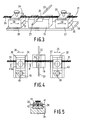
- FIGS. 4 and 5 An exemplary embodiment for such an adjustment possibility is indicated in FIGS. 4 and 5.
- the holding blocks 33 and 34 are movable on a base plate, not shown (corresponding to position 18 in FIG. 3) in the direction of the arrows 35 and 36, respectively. Perpendicular to this in the direction of the welding electrodes 22 and 23, guide brackets 37 and 38 in sliding guides of the holding blocks 33 and 34 can be pressed against adjustable stops 39 and 40.
- the holding blocks have positive locking pins 41 and 42 which engage in the associated positive locking recesses in the holding clips 43 and 44, respectively. The position of the positive locking pins 41 and 42 can be changed by rotating the adjustable stops 39 and 40 relative to the welding electrodes 22 and 23, since the six stop faces 45 have different distances from the axes of rotation of the adjustable stops 39 and 40, respectively.
Landscapes
- Physics & Mathematics (AREA)
- Engineering & Computer Science (AREA)
- Plasma & Fusion (AREA)
- General Physics & Mathematics (AREA)
- Optics & Photonics (AREA)
- Mechanical Coupling Of Light Guides (AREA)
Applications Claiming Priority (2)
| Application Number | Priority Date | Filing Date | Title |
|---|---|---|---|
| DE19904025351 DE4025351A1 (de) | 1990-08-10 | 1990-08-10 | Einrichtung zum verschweissen zweier gruppen von lichtwellenleitern |
| DE4025351 | 1990-08-10 |
Publications (1)
| Publication Number | Publication Date |
|---|---|
| EP0475474A1 true EP0475474A1 (fr) | 1992-03-18 |
Family
ID=6411990
Family Applications (1)
| Application Number | Title | Priority Date | Filing Date |
|---|---|---|---|
| EP91202020A Withdrawn EP0475474A1 (fr) | 1990-08-10 | 1991-08-06 | Dispositif pour le soudage de deux groupes de fibres optiques |
Country Status (3)
| Country | Link |
|---|---|
| EP (1) | EP0475474A1 (fr) |
| JP (1) | JPH04240807A (fr) |
| DE (1) | DE4025351A1 (fr) |
Cited By (3)
| Publication number | Priority date | Publication date | Assignee | Title |
|---|---|---|---|---|
| WO2000008497A2 (fr) * | 1998-08-06 | 2000-02-17 | Siemens Aktiengesellschaft | Dispositif pour fixer de maniere temporaire des extremites de fibres optiques, dans une position definie |
| CN107442933A (zh) * | 2016-06-01 | 2017-12-08 | 泰科电子(上海)有限公司 | 焊接系统和焊接方法 |
| CN107741615A (zh) * | 2017-10-16 | 2018-02-27 | 深圳市中科智诚科技有限公司 | 一种便于纤芯对准的光纤熔接机 |
Families Citing this family (5)
| Publication number | Priority date | Publication date | Assignee | Title |
|---|---|---|---|---|
| JP3737107B2 (ja) * | 1993-11-29 | 2006-01-18 | テレフオンアクチーボラゲツト エル エム エリクソン | 光学的な軸非対称性を持つ光ファイバの間の角オフセットの決定とファイバの芯合わせおよび継ぎ合わせ |
| US6207922B1 (en) | 1994-03-08 | 2001-03-27 | Telefonaktiebolaget Lm Ericsson (Publ) | Electric control for welding optical fibers |
| SE502563C2 (sv) * | 1994-03-08 | 1995-11-13 | Ericsson Telefon Ab L M | Sätt och anordning för att skarva optiska fibrer, samt användning av sättet för framställning av en skarv med förutbestämd dämpning |
| SE512382C2 (sv) * | 1994-04-26 | 2000-03-06 | Ericsson Telefon Ab L M | Anordning och förfarande för att placera långsträckta element mot eller invid en yta |
| SE520464C2 (sv) * | 1997-05-23 | 2003-07-15 | Ericsson Telefon Ab L M | Hållare för optiska fibrer samt anordning för hopsvetsning av optiska fibrer |
Citations (3)
| Publication number | Priority date | Publication date | Assignee | Title |
|---|---|---|---|---|
| EP0069832A1 (fr) * | 1981-07-15 | 1983-01-19 | ANT Nachrichtentechnik GmbH | Procédé pour le raccordement simultané de plusieurs fibres optiques |
| EP0211221A1 (fr) * | 1985-06-28 | 1987-02-25 | Sumitomo Electric Industries Limited | Méthode et appareil pour le couplage de câbles de fibres optiques multiples munies d'un revêtement |
| EP0340867A2 (fr) * | 1988-05-06 | 1989-11-08 | Philips Patentverwaltung GmbH | Méthode et dispositif pour monter une multipicité de guides d'ondes lumineuses dans une pince étau |
-
1990
- 1990-08-10 DE DE19904025351 patent/DE4025351A1/de not_active Withdrawn
-
1991
- 1991-08-05 JP JP19529891A patent/JPH04240807A/ja active Pending
- 1991-08-06 EP EP91202020A patent/EP0475474A1/fr not_active Withdrawn
Patent Citations (3)
| Publication number | Priority date | Publication date | Assignee | Title |
|---|---|---|---|---|
| EP0069832A1 (fr) * | 1981-07-15 | 1983-01-19 | ANT Nachrichtentechnik GmbH | Procédé pour le raccordement simultané de plusieurs fibres optiques |
| EP0211221A1 (fr) * | 1985-06-28 | 1987-02-25 | Sumitomo Electric Industries Limited | Méthode et appareil pour le couplage de câbles de fibres optiques multiples munies d'un revêtement |
| EP0340867A2 (fr) * | 1988-05-06 | 1989-11-08 | Philips Patentverwaltung GmbH | Méthode et dispositif pour monter une multipicité de guides d'ondes lumineuses dans une pince étau |
Non-Patent Citations (2)
| Title |
|---|
| I.E.E.E. JOURNAL ON SELECTED AREAS IN COMMUNICATIONS Band SAC-4, Nr. 5, August 1986, Seiten 706-713, New York, NY, US; K. INADA et al.: "Splicing of Fibers by the Fusion Method" * |
| JOURNAL OF LIGHTWAVE TECHNOLOGY Band LT-2, Nr. 1, 1984, Seiten 25-31, New York, US; M. TACHIKURA et al.: "Fusion mass-splices for optical fibers using high-frequency discharge" * |
Cited By (7)
| Publication number | Priority date | Publication date | Assignee | Title |
|---|---|---|---|---|
| WO2000008497A2 (fr) * | 1998-08-06 | 2000-02-17 | Siemens Aktiengesellschaft | Dispositif pour fixer de maniere temporaire des extremites de fibres optiques, dans une position definie |
| WO2000008497A3 (fr) * | 1998-08-06 | 2000-09-08 | Siemens Ag | Dispositif pour fixer de maniere temporaire des extremites de fibres optiques, dans une position definie |
| US6438312B1 (en) | 1998-08-06 | 2002-08-20 | Siemens Aktiengesellschaft | Apparatus for temporarily fixing light waveguide ends in a defined position |
| AU753193B2 (en) * | 1998-08-06 | 2002-10-10 | Siemens Aktiengesellschaft | Device for temporarily fixing optical waveguide ends in a position-defined manner |
| CN107442933A (zh) * | 2016-06-01 | 2017-12-08 | 泰科电子(上海)有限公司 | 焊接系统和焊接方法 |
| CN107741615A (zh) * | 2017-10-16 | 2018-02-27 | 深圳市中科智诚科技有限公司 | 一种便于纤芯对准的光纤熔接机 |
| CN107741615B (zh) * | 2017-10-16 | 2020-04-17 | 杭州金龙光电缆有限公司 | 一种便于纤芯对准的光纤熔接机 |
Also Published As
| Publication number | Publication date |
|---|---|
| JPH04240807A (ja) | 1992-08-28 |
| DE4025351A1 (de) | 1992-02-13 |
Similar Documents
| Publication | Publication Date | Title |
|---|---|---|
| DE2626907C2 (de) | Kupplung für optische Fasern | |
| DE2522740C3 (de) | Vorrichtung zum Verbinden eines ankommenden Lichtleitfaserkabels mit einem weiterführenden und Verfahren zur Herstellung der Vorrichtung | |
| DE2726913B2 (de) | Vorrichtung zum Verbinden zweier ummantelter Einzellichtleitfasern | |
| DE2518319B1 (de) | Loesbare Spleissverbindung fuer Lichtwellenleiterkabel | |
| DE2759002C3 (de) | Steckverbinder zur lösbaren Verbindung zweier Lichtwellenleiter-Kabel | |
| EP0475474A1 (fr) | Dispositif pour le soudage de deux groupes de fibres optiques | |
| DE2826032B2 (de) | Lösbare Steckverbindung für Lichtleitfasern und zugehörige Montagelehre | |
| DE2530883C3 (de) | Verfahren zum Verbinden von Einzellichtwellenleitern | |
| DE2951483A1 (de) | Spleissvorrichtung zum herstellen von lichtwellenleiterverbindungen | |
| EP0340867B1 (fr) | Méthode et dispositif pour monter une multipicité de guides d'ondes lumineuses dans une pince étau | |
| DE2733167C2 (de) | Armatur zum Steckverbinden zweier Lichtleitfasern | |
| DE3325157A1 (de) | Schweissvorrichtung fuer lichtwellenleiterkabel | |
| DE10113740A1 (de) | Vorrichtung zum Bearbeiten einer isolierten optischen Faser | |
| EP0244004A2 (fr) | Dispositif de couplage des fins de deux groupes de guides d'ondes lumineuses sur fibres | |
| DE3225657C2 (de) | Einrichtung zur Herstellung einer mechanischen, nicht lösbaren Spleißverbindung zweier Lichtwellenleiter (LWL) aus Quarzglas | |
| DE2932723B2 (de) | Vorrichtung zur Herstellung unlösbarer Verbindungen von Lichtwellenleitern | |
| DE3338493A1 (de) | Verfahren zum spleissen von glasfaser-buendeladern und vorrichtung zur durchfuehrung des verfahrens | |
| DE4307974C1 (de) | Vorrichtung zur hochgenauen Drehung rotationssymmetrischer Bauteile, insbesondere von Lichtwellenleitern | |
| DE4006799A1 (de) | Verfahren zur herstellung einer schweissverbindungsstelle zwischen zwei gruppen von lichtwellenleitern und vorrichtung zur ausuebung des verfahrens | |
| EP1103010B1 (fr) | Dispositif pour fixer de maniere temporaire des extremites de fibres optiques, dans une position definie | |
| DE4018226C2 (fr) | ||
| DE3105156A1 (de) | Vorrichtung zur herstellung unloesbarer verbindungen von lichtwellenleitern | |
| DE3017453A1 (de) | Muffe | |
| DE3230098A1 (de) | Vorrichtung zum loesbaren verbinden von lichtleitern, lichtleiterbaendern und lichtleiterbuendeln | |
| DE3831723C1 (en) | Scheme having at least one exactly positioned optical waveguide, and use of the scheme |
Legal Events
| Date | Code | Title | Description |
|---|---|---|---|
| PUAI | Public reference made under article 153(3) epc to a published international application that has entered the european phase |
Free format text: ORIGINAL CODE: 0009012 |
|
| AK | Designated contracting states |
Kind code of ref document: A1 Designated state(s): DE ES FR GB IT |
|
| 17P | Request for examination filed |
Effective date: 19920918 |
|
| 17Q | First examination report despatched |
Effective date: 19940531 |
|
| STAA | Information on the status of an ep patent application or granted ep patent |
Free format text: STATUS: THE APPLICATION IS DEEMED TO BE WITHDRAWN |
|
| 18D | Application deemed to be withdrawn |
Effective date: 19941011 |