EP0473975A2 - Schaber für Filteranlage - Google Patents
Schaber für Filteranlage Download PDFInfo
- Publication number
- EP0473975A2 EP0473975A2 EP91113495A EP91113495A EP0473975A2 EP 0473975 A2 EP0473975 A2 EP 0473975A2 EP 91113495 A EP91113495 A EP 91113495A EP 91113495 A EP91113495 A EP 91113495A EP 0473975 A2 EP0473975 A2 EP 0473975A2
- Authority
- EP
- European Patent Office
- Prior art keywords
- scraper
- filter
- spiral
- segment
- filter system
- Prior art date
- Legal status (The legal status is an assumption and is not a legal conclusion. Google has not performed a legal analysis and makes no representation as to the accuracy of the status listed.)
- Withdrawn
Links
- 239000012065 filter cake Substances 0.000 claims description 11
- 239000000463 material Substances 0.000 claims description 10
- 238000004804 winding Methods 0.000 claims description 3
- 230000001154 acute effect Effects 0.000 claims 1
- 239000007787 solid Substances 0.000 abstract description 7
- 239000007788 liquid Substances 0.000 description 20
- 239000000706 filtrate Substances 0.000 description 6
- 238000007790 scraping Methods 0.000 description 5
- 235000010469 Glycine max Nutrition 0.000 description 4
- 244000068988 Glycine max Species 0.000 description 4
- 230000000694 effects Effects 0.000 description 4
- 230000007423 decrease Effects 0.000 description 3
- 238000001914 filtration Methods 0.000 description 3
- 230000000717 retained effect Effects 0.000 description 2
- 239000002002 slurry Substances 0.000 description 2
- 229910001220 stainless steel Inorganic materials 0.000 description 2
- 239000010935 stainless steel Substances 0.000 description 2
- 239000004809 Teflon Substances 0.000 description 1
- 229920006362 Teflon® Polymers 0.000 description 1
- 238000005299 abrasion Methods 0.000 description 1
- 239000000853 adhesive Substances 0.000 description 1
- 230000001070 adhesive effect Effects 0.000 description 1
- 235000013305 food Nutrition 0.000 description 1
- 235000021056 liquid food Nutrition 0.000 description 1
- 238000000034 method Methods 0.000 description 1
- 235000013336 milk Nutrition 0.000 description 1
- 239000008267 milk Substances 0.000 description 1
- 210000004080 milk Anatomy 0.000 description 1
- 230000002093 peripheral effect Effects 0.000 description 1
- 239000004033 plastic Substances 0.000 description 1
- 238000000926 separation method Methods 0.000 description 1
- 235000013322 soy milk Nutrition 0.000 description 1
- 239000000126 substance Substances 0.000 description 1
- 229920003002 synthetic resin Polymers 0.000 description 1
- 239000000057 synthetic resin Substances 0.000 description 1
Images


Classifications
-
- B—PERFORMING OPERATIONS; TRANSPORTING
- B01—PHYSICAL OR CHEMICAL PROCESSES OR APPARATUS IN GENERAL
- B01D—SEPARATION
- B01D24/00—Filters comprising loose filtering material, i.e. filtering material without any binder between the individual particles or fibres thereof
-
- B—PERFORMING OPERATIONS; TRANSPORTING
- B30—PRESSES
- B30B—PRESSES IN GENERAL
- B30B9/00—Presses specially adapted for particular purposes
- B30B9/02—Presses specially adapted for particular purposes for squeezing-out liquid from liquid-containing material, e.g. juice from fruits, oil from oil-containing material
- B30B9/12—Presses specially adapted for particular purposes for squeezing-out liquid from liquid-containing material, e.g. juice from fruits, oil from oil-containing material using pressing worms or screws co-operating with a permeable casing
- B30B9/14—Presses specially adapted for particular purposes for squeezing-out liquid from liquid-containing material, e.g. juice from fruits, oil from oil-containing material using pressing worms or screws co-operating with a permeable casing operating with only one screw or worm
-
- B—PERFORMING OPERATIONS; TRANSPORTING
- B01—PHYSICAL OR CHEMICAL PROCESSES OR APPARATUS IN GENERAL
- B01D—SEPARATION
- B01D29/00—Filters with filtering elements stationary during filtration, e.g. pressure or suction filters, not covered by groups B01D24/00 - B01D27/00; Filtering elements therefor
- B01D29/11—Filters with filtering elements stationary during filtration, e.g. pressure or suction filters, not covered by groups B01D24/00 - B01D27/00; Filtering elements therefor with bag, cage, hose, tube, sleeve or like filtering elements
- B01D29/13—Supported filter elements
- B01D29/23—Supported filter elements arranged for outward flow filtration
- B01D29/25—Supported filter elements arranged for outward flow filtration open-ended the arrival of the mixture to be filtered and the discharge of the concentrated mixture are situated on both opposite sides of the filtering element
-
- B—PERFORMING OPERATIONS; TRANSPORTING
- B01—PHYSICAL OR CHEMICAL PROCESSES OR APPARATUS IN GENERAL
- B01D—SEPARATION
- B01D29/00—Filters with filtering elements stationary during filtration, e.g. pressure or suction filters, not covered by groups B01D24/00 - B01D27/00; Filtering elements therefor
- B01D29/44—Edge filtering elements, i.e. using contiguous impervious surfaces
- B01D29/48—Edge filtering elements, i.e. using contiguous impervious surfaces of spirally or helically wound bodies
-
- B—PERFORMING OPERATIONS; TRANSPORTING
- B01—PHYSICAL OR CHEMICAL PROCESSES OR APPARATUS IN GENERAL
- B01D—SEPARATION
- B01D29/00—Filters with filtering elements stationary during filtration, e.g. pressure or suction filters, not covered by groups B01D24/00 - B01D27/00; Filtering elements therefor
- B01D29/62—Regenerating the filter material in the filter
- B01D29/64—Regenerating the filter material in the filter by scrapers, brushes, nozzles, or the like, acting on the cake side of the filtering element
- B01D29/6469—Regenerating the filter material in the filter by scrapers, brushes, nozzles, or the like, acting on the cake side of the filtering element scrapers
- B01D29/6476—Regenerating the filter material in the filter by scrapers, brushes, nozzles, or the like, acting on the cake side of the filtering element scrapers with a rotary movement with respect to the filtering element
-
- B—PERFORMING OPERATIONS; TRANSPORTING
- B01—PHYSICAL OR CHEMICAL PROCESSES OR APPARATUS IN GENERAL
- B01D—SEPARATION
- B01D29/00—Filters with filtering elements stationary during filtration, e.g. pressure or suction filters, not covered by groups B01D24/00 - B01D27/00; Filtering elements therefor
- B01D29/76—Handling the filter cake in the filter for purposes other than for regenerating
- B01D29/80—Handling the filter cake in the filter for purposes other than for regenerating for drying
- B01D29/82—Handling the filter cake in the filter for purposes other than for regenerating for drying by compression
Definitions
- the present invention relates to a scraper filter system incluing scraper means, and more particularly to a filter system in which an improved scraper means consisting of a plurality of separate scraper segments is provided and proper scraping operation is steadily maintained.
- a scraper made of a wear resistant material is provided at the edge of a spiral impeller in a cylindrical filter, constantly engaged with the inner area of the cylindrical filter, and a filtrate from a feed liquid such as highly viscous liquid food is discharged from the outside of the cylindrical filter while the feed liquid is delivered with no loss of feeding pressure from the inlet to the outlet port for the feed liquid until the concentrated food solid is finally taken out from the cylinder.
- the filters have an advantage that since the scraper is prepared in the ways that coil springs are incorporated into the scraper made of a wear resistant long plastic board and fixed in a groove formed along the spiral edge of the impeller, the edge of the scraper is closely engaged with the inner area of the cylindrical filter in virtue of expansion of the coil springs.
- the 1 pitch length of the scraper with no wear and engage with the filter surface is regarded as the same as the inner circumference of the filter, the 1 pitch length can be expressed: R ⁇ (cm) (2) ( the length is considered as a circle )
- an object of the present invention is to be provide an improved structure for the scraper in which despite being suffered from some wear on the scraper the scraper is never shifted and is able to be constantly engaged with the filter surface.
- a scraper is independently separated into a plurality of scraper segments and attached along the edge of a spiral impeller located in a cylindrical filter.
- a first feature of the present invention is that a spiral impeller which is freely rotatable within a cylinder around the inner surface of which is provided with a plurality of filter slits or holes having a desired dimension is set in a cylinder.
- a second feature of the present invention is that a scraper system in which it is separated into a plurality of scraping segments associated with springs each end of which is slways engaged closely with the inner surface of cylindrical filter, and each scraper segment is firmly attached in position on the spiral edge of the impeller, so that each scraper segment is never be shifted.
- a third feature of the present invention is that in order to prevent a spiral impeller from losing its feeding pressure every adjacent scraper segments are overlapped at each end.
- a fourth feature of the present invention is that each scraper segment is integrally combined with a spring board by which the end of each segment is constantly maintained to engage the inner surface of the filter and each scraper segment is firmly attached into a groove formed on a separate position on the spiral edge of the impeller.
- a fifth feature of the present invention is that each scraper segment associated with a coil spring is attached into a groove formed on a separated position of the spiral edge of the impeller, so that the end of each segment is raised up by the force of the spring.
- a sixth feature of the present invention is that providing each groove with two projections corresponding to the length of a scraper segment in order to prevent it from being shifted.
- a seventh feature of the present invention is that the one side of each segment which is faced toward the feed liquid inlet and exposed at a higer pressure from high content of solid matter is protectively ma de of a more unabrasive material than that in other side of each segment which is faced toward the feed liquid inlet and exposed at lower pressure.
- An eighth feature of the present invention is that a cone can be used as well as a cylinder as a filter body.
- a nineth feature of the present invention is that along the inner surface of said cylinfder or cone is fixedly coiled a long straight line of hard material such as stainless steel the cross section of which is a isosceles triangle to form a filter slit between every adjacent coils.
- a tenth feature of the present invention is that said straight line is coiled in a way that the vertex of triangleis directed to outside of the cylindrical surface and that the base of each triangle is directed to inside to flush with each other.
- An eleventh feature of the present invention is that the cross section of a long straight line is a circle and that the line is coiled along the inner area of a cylindrical or conical surface to form a filter slit between every adjacent coils.
- the scraper system of the present invention is composed of a plurality of discrete scraping segments which are strongly prevented from being moved or shifted from their definite positions on the spiral edge of the impeller along with the end of each segment being always engage with the inner cylindrical surface of the filter by force of springs, there never occurs any shifts of scraper segments toward the axis of the impeller whatever wear of the scraper segments occurs on account of any strong rotation of the spiral impeller.
- the separately disposed scraper segments on the spiral edge of the impeller do prevent any scraper segments from having any unengaged area on the filter due to the wear of the scrapers.
- each groove formed on the spiral edge of the impeller with two projections corresponding to the length of a scraper segment will enable for each scraper segment never to be shifted.
- each separate scraper segment is combined with a leaf spring or a coil spring beneath the base of each scraper segment, the end of each scraper segment constantly receives force of the spring which makes each scraper segment constantly engageable closely with the inner surface of the cylindrical filter.
- each separate scraper segment is scarcely damaged by wear because the one side of each segment, which is faced toward the outlet of the cylinder and exposed at a higer pressure from the concentrated solid matter of a feed liquid, is made of a higher wear resistant material than that in the other side of each segment, which is faced toward the inlet of the cylinder and exposed at lower pressure from the feed liquid.
- a frusto-conical as well as a straight cylindrical shape can be used as a filter element.
- a long straight line of hard material such as stainless steel the cross section of which is a isosceles triangle or circle to form a filter slit between every adjacent windings.
- the embodiment described herein is suitable for soy milk separation from soybean slurry.
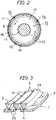
- a reference numeral 1 denotes a cylindrical filter element, which comprises a wire rod filter member 2 having a triangular section wound as a spiral form around an inner surface of a cylindrical support member 3 having a plurality of flow holes.
- the wire member 2 is retained with its accute apex 2b in a spiral groove 4 formed along the inner surface of support member 3, so as to permit all adjacent surfaces ⁇ of wire member 2 to be flush with each other, leaving a spiral filter slit 5 of a definite width around the surface.
- a reference numeral 6 denotes a cylindrical casing selectively enclosing one or more filter elements 1. At one end of the casing 6, a feed liquid inlet 7 is provided. At another end, a filter cake discharge assembly 9 including a discharge outlet 8 is provided.
- a screw member or rotor 10 is formed of a screw-formed spiral impeller 12.
- the spiral impeller 12 consists of a plurality of discrete blades secured to the rotating shaft 11, and is rotatably supported within the filter element 1 so as to leave a small clearance against the internal surface of filter element 1.
- spiral impeller 12 can be formed as an integral member (not illustrated) instead of discrete blades.
- spiral impeller 12 is formed to have a definite diameter throughout the length thereof.
- the spiral is formed so as to convey the liquid in the direction from the inlet 7 to the outlet 8, and is further formed so that the pitch gradually decreases as the outlet 8, is approached for applying an efficient squeeze effect on the liquid.
- a numeral 19 denotes drive means connected to a rotation shaft 11 of screw member 10, which is connected to an electric motor 20 through belt 21 or gear means.
- the shaft 11 has its both ends 11a and 11b rotatably supported.
- Filter cake dicharge assembly 9 includes a cap assembly 25 and a support frame 27.
- the former includes hand-operating wheel 22, threaded shaft 23 and cap member 24, and the latter forms a part of frame assembly 26 and threadably supports the above threaded shaft 23.
- the opening extent can be desirably adjusted between the first tapered surface 28 of cap member 24 and another tapered surface 29 of discharge outlet 8 which faces the first tapered surface.
- a filtrate collection cylinder 30 to which a filtrate outlet 31 is attached.
- a numeral 32 denotes a hopper beneath the outlet 8.
- a feed liquid to be filtered such as soybean raw s lurry is fed through the feed liquid inlet after screw member 10 is rotated by drive means 13.
- the filtrate passed through the filter slit is collected as soybean milk, which is drained through filtrate outlet 31.
- the filter cakes can be readily removed, because the spiral impeller 12 according to the invention is free from any obstacles, such as stays for supporting the scraper means which can prevent removing of deposited filter cakes. As a result, filter cakes are successively transferred without causing blinding of filter elements during filter operation.
- the rotary shaft 11 can be formed to successively increase its diameter, and spiral impeller 12 is formed to decrease its pitch, thereby increasing squeeze effect to gradually accumulate filter cakes near the cake discharge outlet 8.
- the clearance between the chamfered fringes of closing member 24 and discharge outlet 8 can be adjusted by timely operating the wheel. As a result, filter cakes containing a desired moisture content can be discharged.
- each scraper segment 15 resilient engagement of each scraper segment 15 with the filtering surface is always effectively maintained by means of resilient means such as a leaf spring 17 or coiled spring. Further, each projection 16 is effective for competely preventing each segment 15 from being axially displaced along the spiral groove 13. Accordingly, even if the length around the spiral edge is reduced due to wear, there causes an external shift of segments merely in the radial direction, without causing any undesired movement within and along the spiral groove 13.
- each overlapped portion 18 of the ends of each segment provides an advangage to maintain such overlapped condition even when the arcuate external edge is reduced in its peripheral length due to wear of the scraping surface. Also, engagement of scraper means with the filtering surface is normally maintained for preventing any trouble such as leakage of the pressure required for proper filter operation.
- a separate coil spring may be used, which is retained with its end portion received in a recess formed in the groove 13 (not illustrated).
- the material for scraper segments 15 is not always specifically restricted. However, a hard synthetic resin such as teflon or a wear resistant material is preferable.
- segments 15 near the filter cake discharge outlet including a higher internal pressure are formed of a higher wear resistant material, while the segments located near the feed liquid inlet are of a lower wear resistant material.
Landscapes
- Chemical & Material Sciences (AREA)
- Chemical Kinetics & Catalysis (AREA)
- Engineering & Computer Science (AREA)
- Mechanical Engineering (AREA)
- Filtration Of Liquid (AREA)
Applications Claiming Priority (2)
| Application Number | Priority Date | Filing Date | Title |
|---|---|---|---|
| JP2214964A JPH0642931B2 (ja) | 1990-08-16 | 1990-08-16 | スクレーパ濾過装置 |
| JP214964/90 | 1990-08-16 |
Publications (2)
| Publication Number | Publication Date |
|---|---|
| EP0473975A2 true EP0473975A2 (de) | 1992-03-11 |
| EP0473975A3 EP0473975A3 (en) | 1992-04-22 |
Family
ID=16664488
Family Applications (1)
| Application Number | Title | Priority Date | Filing Date |
|---|---|---|---|
| EP19910113495 Withdrawn EP0473975A3 (en) | 1990-08-16 | 1991-08-12 | Scraper filter system |
Country Status (4)
| Country | Link |
|---|---|
| US (1) | US5186834A (de) |
| EP (1) | EP0473975A3 (de) |
| JP (1) | JPH0642931B2 (de) |
| KR (1) | KR950001972B1 (de) |
Cited By (8)
| Publication number | Priority date | Publication date | Assignee | Title |
|---|---|---|---|---|
| US5476178A (en) * | 1993-06-16 | 1995-12-19 | E & M Lamort | Rotor for pressurized hydrodynamic purification of paper pulp and equipment fitted with this rotor |
| WO2005023394A3 (en) * | 2003-09-03 | 2005-05-12 | Capital Formation Inc | Filter assembly with sealed, magnetically coupled cleaning head actuator |
| WO2011002317A1 (en) * | 2009-07-01 | 2011-01-06 | Gregory Richard Morgan | Improvements relating to filtration and dewatering apparatus |
| CN102990963A (zh) * | 2012-11-27 | 2013-03-27 | 由达集团有限公司 | 榨油磨粉机 |
| EP3112006A1 (de) * | 2015-06-24 | 2017-01-04 | Betebe GmbH | Schneckenfilter |
| CN106621520A (zh) * | 2017-02-07 | 2017-05-10 | 浙江精锐机械科技有限公司 | 一种过滤、洗涤、干燥三合一装置 |
| CN110947226A (zh) * | 2019-11-19 | 2020-04-03 | 佛山科学技术学院 | 一种污水处理用固液预分离装置 |
| CN111991887A (zh) * | 2020-08-17 | 2020-11-27 | 广州红尚机械制造有限公司 | 刮板过滤器 |
Families Citing this family (17)
| Publication number | Priority date | Publication date | Assignee | Title |
|---|---|---|---|---|
| GB9504908D0 (en) * | 1995-03-10 | 1995-04-26 | Bellhouse Brian John | Filter |
| JP2819398B2 (ja) | 1995-04-06 | 1998-10-30 | 丸井工業株式会社 | 豆腐製造用の圧搾機および圧搾方法 |
| EP1057533A1 (de) * | 1999-05-27 | 2000-12-06 | Ferrum AG | Zentrifuge |
| DE20010933U1 (de) * | 2000-06-27 | 2001-09-13 | Weh, Erwin, 89257 Illertissen | Filterteil für Fluidleitungen |
| GB0122316D0 (en) * | 2001-09-15 | 2001-11-07 | Wedge Wire Screens Ltd | Threaded article |
| JP4633670B2 (ja) * | 2006-04-28 | 2011-02-16 | 株式会社荒井鉄工所 | スクレーパおよびその流体の濾過装置 |
| US8813973B2 (en) * | 2008-05-05 | 2014-08-26 | Fluid-Quip, Inc. | Apparatus and method for filtering a material from a liquid medium |
| WO2011092819A1 (ja) * | 2010-01-28 | 2011-08-04 | 株式会社荒井鉄工所 | 分割スクレーパおよびその流体の濾過ないし移送装置 |
| KR101221087B1 (ko) * | 2010-04-26 | 2013-01-11 | 박병용 | 코일형 필터를 사용하는 이물질 분리장치 |
| AT12606U1 (de) * | 2011-05-20 | 2012-08-15 | Applied Chemicals Handels Gmbh | Schneckenpresse |
| ITBO20120357A1 (it) * | 2012-06-27 | 2013-12-28 | Carpigiani Group Ali Spa | Agitatore di una macchina per la produzione e l'erogazione di prodotti di gelateria |
| US9180389B2 (en) * | 2013-11-26 | 2015-11-10 | Shenzhen China Star Optoelectronics Technology Co., Ltd | Filter |
| JP6037319B1 (ja) * | 2015-06-04 | 2016-12-07 | 月島機械株式会社 | 縦型濾過濃縮装置 |
| JP2017000910A (ja) * | 2015-06-04 | 2017-01-05 | 月島機械株式会社 | 縦型濾過濃縮装置 |
| JP2017018895A (ja) * | 2015-07-10 | 2017-01-26 | 神奈川機器工業株式会社 | フィルタエレメント、逆洗型ろ過装置、及びフィルタエレメントのろ過方法及び逆洗方法 |
| DK201870747A1 (en) * | 2018-11-14 | 2020-06-23 | Bollfilter Nordic Aps | Filter candle and method for operating such filter candle |
| US11484818B2 (en) * | 2019-02-11 | 2022-11-01 | North Carolina State University | Self-cleaning screen |
Family Cites Families (15)
| Publication number | Priority date | Publication date | Assignee | Title |
|---|---|---|---|---|
| DE87368C (de) * | ||||
| US854288A (en) * | 1907-01-25 | 1907-05-21 | Thomas W Goreau | Filter. |
| DE620876C (de) * | 1933-09-26 | 1935-10-29 | Dommitzscher Tonwerke Akt Ges | Schneckenanordnung an Schneckenpressen fuer keramische Massen |
| US2607679A (en) * | 1947-02-17 | 1952-08-19 | Buckeye Cotton Oil Company | Apparatus for removing liquid from cotton linters |
| US3216818A (en) * | 1964-10-21 | 1965-11-09 | Hudson Hugh Paul | Process for smelting ore with a cyclone combustor |
| US3721184A (en) * | 1971-07-09 | 1973-03-20 | French Oil Mill Machinery | Mechanical screw press |
| US3695173A (en) * | 1972-01-28 | 1972-10-03 | Clyde Harold Cox | Sludge dewatering |
| US3938434A (en) * | 1973-03-19 | 1976-02-17 | Cox Clyde H | Sludge dewatering |
| US4041854A (en) * | 1974-06-10 | 1977-08-16 | Cox Clyde H | Sludge dewatering |
| CH621489A5 (de) * | 1977-06-09 | 1981-02-13 | Lonza Ag | |
| US4347134A (en) * | 1981-09-03 | 1982-08-31 | Svehaug Oswald C | Slurry separator having reaction nozzle driven rotory blades wiping a conical filter |
| US4470904A (en) * | 1981-10-28 | 1984-09-11 | Josef Gail | Mechanism for separating materials of varying consistency |
| JPH02211998A (ja) * | 1989-02-14 | 1990-08-23 | Arai Tekkosho:Kk | 筒型固液分離装置 |
| US5061366A (en) * | 1989-04-28 | 1991-10-29 | Arai Corporation | Scraper filter system |
| US5087365A (en) * | 1990-06-14 | 1992-02-11 | Delaware Capital Formation, Inc. | Filter with rotating wiper having indexing blades |
-
1990
- 1990-08-16 JP JP2214964A patent/JPH0642931B2/ja not_active Expired - Lifetime
-
1991
- 1991-08-06 US US07/740,960 patent/US5186834A/en not_active Expired - Lifetime
- 1991-08-12 EP EP19910113495 patent/EP0473975A3/en not_active Withdrawn
- 1991-08-16 KR KR1019910014153A patent/KR950001972B1/ko not_active Expired - Lifetime
Cited By (16)
| Publication number | Priority date | Publication date | Assignee | Title |
|---|---|---|---|---|
| US5476178A (en) * | 1993-06-16 | 1995-12-19 | E & M Lamort | Rotor for pressurized hydrodynamic purification of paper pulp and equipment fitted with this rotor |
| CN102764532A (zh) * | 2003-09-03 | 2012-11-07 | 伊顿工业制造有限公司 | 清洗头 |
| WO2005023394A3 (en) * | 2003-09-03 | 2005-05-12 | Capital Formation Inc | Filter assembly with sealed, magnetically coupled cleaning head actuator |
| US7093721B2 (en) | 2003-09-03 | 2006-08-22 | Delaware Corporation Formation, Inc. | Filter assembly with sealed, magnetically coupled cleaning head actuator |
| CN100421761C (zh) * | 2003-09-03 | 2008-10-01 | 特拉华资本构造公司 | 具有密封的磁耦合清洗头致动器的过滤器组件 |
| EP2308577A1 (de) * | 2003-09-03 | 2011-04-13 | Eaton LP | Reinigungskopf für eine Filtervorrichtung |
| EP2316555A1 (de) * | 2003-09-03 | 2011-05-04 | Eaton LP | Reinigungskopf für eine Filtervorrichtung |
| CN101357277B (zh) * | 2003-09-03 | 2012-06-13 | 伊顿工业制造有限公司 | 清洗叶片和清洗头 |
| WO2011002317A1 (en) * | 2009-07-01 | 2011-01-06 | Gregory Richard Morgan | Improvements relating to filtration and dewatering apparatus |
| US9358482B2 (en) | 2009-07-01 | 2016-06-07 | Liquidstrip Limited | Filtration and dewatering apparatus |
| CN102990963A (zh) * | 2012-11-27 | 2013-03-27 | 由达集团有限公司 | 榨油磨粉机 |
| CN102990963B (zh) * | 2012-11-27 | 2015-04-22 | 由达集团有限公司 | 榨油磨粉机 |
| EP3112006A1 (de) * | 2015-06-24 | 2017-01-04 | Betebe GmbH | Schneckenfilter |
| CN106621520A (zh) * | 2017-02-07 | 2017-05-10 | 浙江精锐机械科技有限公司 | 一种过滤、洗涤、干燥三合一装置 |
| CN110947226A (zh) * | 2019-11-19 | 2020-04-03 | 佛山科学技术学院 | 一种污水处理用固液预分离装置 |
| CN111991887A (zh) * | 2020-08-17 | 2020-11-27 | 广州红尚机械制造有限公司 | 刮板过滤器 |
Also Published As
| Publication number | Publication date |
|---|---|
| KR950001972B1 (ko) | 1995-03-08 |
| JPH0642931B2 (ja) | 1994-06-08 |
| JPH04100502A (ja) | 1992-04-02 |
| US5186834A (en) | 1993-02-16 |
| KR920004012A (ko) | 1992-03-27 |
| EP0473975A3 (en) | 1992-04-22 |
Similar Documents
| Publication | Publication Date | Title |
|---|---|---|
| EP0473975A2 (de) | Schaber für Filteranlage | |
| US5061366A (en) | Scraper filter system | |
| US4634524A (en) | Device for removing screened or sifted material from liquid flowing in a gutter | |
| EP0664727B1 (de) | Verschleissfester korb für eine mit schnecke versehene zentrifuge | |
| DE68907555T2 (de) | Verflüssigende Kreiselpumpe oder Laufrad für solche Pumpe. | |
| AU708860B2 (en) | A decanter centrifuge | |
| DE2407653A1 (de) | Zentrifugenpatrone | |
| PL205899B1 (pl) | Urządzenie do ciągłego filtrowania mieszanin materiałów | |
| EP0696227A1 (de) | Rotierender filter | |
| GB2067911A (en) | Strainer for purification of pulp | |
| SE515591C2 (sv) | Skruvpress för att separera vätskor från blandningar av fasta partiklar och vätskor | |
| DE4106248A1 (de) | Zentrifugaltrockner zur trennung von oberflaechenwasser von kunststoffgranulat | |
| EP0135146A2 (de) | Entleerungsvorrichtung für Materialien | |
| US5674396A (en) | Rotary filter with a device for separating a solids/liquid mixture, particularly a pulp suspension | |
| DE19718502A1 (de) | Einrichtung zur Schlammentwässerung | |
| SE438101B (sv) | Baktvettbart filter | |
| JP2745453B2 (ja) | 固液分離装置 | |
| AU632088B2 (en) | Screen bowl centrifuge | |
| US4530761A (en) | Extrusion devices | |
| CA1135635A (en) | Screening device | |
| DE202011105998U1 (de) | Separator zur Abtrennung von Feststoffen aus insbesondere hochviskosen Flüssigkeiten | |
| JP3291724B2 (ja) | 遠心脱水機のスクレーパー装置 | |
| US4054528A (en) | Self-cleaning strainer or filter | |
| CA1329147C (en) | Arrangement at rotating filters for improved filtrate discharge | |
| JPS6321994Y2 (de) |
Legal Events
| Date | Code | Title | Description |
|---|---|---|---|
| PUAI | Public reference made under article 153(3) epc to a published international application that has entered the european phase |
Free format text: ORIGINAL CODE: 0009012 |
|
| PUAL | Search report despatched |
Free format text: ORIGINAL CODE: 0009013 |
|
| AK | Designated contracting states |
Kind code of ref document: A2 Designated state(s): CH DE FR GB LI NL |
|
| AK | Designated contracting states |
Kind code of ref document: A3 Designated state(s): CH DE FR GB LI NL |
|
| 17P | Request for examination filed |
Effective date: 19920827 |
|
| 17Q | First examination report despatched |
Effective date: 19931125 |
|
| STAA | Information on the status of an ep patent application or granted ep patent |
Free format text: STATUS: THE APPLICATION IS DEEMED TO BE WITHDRAWN |
|
| 18D | Application deemed to be withdrawn |
Effective date: 19951010 |