EP0472284A1 - Fahrzeugaufbauten - Google Patents
Fahrzeugaufbauten Download PDFInfo
- Publication number
- EP0472284A1 EP0472284A1 EP19910306483 EP91306483A EP0472284A1 EP 0472284 A1 EP0472284 A1 EP 0472284A1 EP 19910306483 EP19910306483 EP 19910306483 EP 91306483 A EP91306483 A EP 91306483A EP 0472284 A1 EP0472284 A1 EP 0472284A1
- Authority
- EP
- European Patent Office
- Prior art keywords
- door
- tie bar
- vehicle body
- formations
- body according
- Prior art date
- Legal status (The legal status is an assumption and is not a legal conclusion. Google has not performed a legal analysis and makes no representation as to the accuracy of the status listed.)
- Granted
Links
- 230000015572 biosynthetic process Effects 0.000 claims description 47
- 238000005755 formation reaction Methods 0.000 claims description 47
- 238000005452 bending Methods 0.000 description 5
- 230000007935 neutral effect Effects 0.000 description 3
- 230000002787 reinforcement Effects 0.000 description 2
- 230000002411 adverse Effects 0.000 description 1
- 230000006835 compression Effects 0.000 description 1
- 238000007906 compression Methods 0.000 description 1
- 230000007423 decrease Effects 0.000 description 1
- 230000001419 dependent effect Effects 0.000 description 1
- 230000004048 modification Effects 0.000 description 1
- 238000012986 modification Methods 0.000 description 1
- 239000000725 suspension Substances 0.000 description 1
Images
Classifications
-
- B—PERFORMING OPERATIONS; TRANSPORTING
- B60—VEHICLES IN GENERAL
- B60J—WINDOWS, WINDSCREENS, NON-FIXED ROOFS, DOORS, OR SIMILAR DEVICES FOR VEHICLES; REMOVABLE EXTERNAL PROTECTIVE COVERINGS SPECIALLY ADAPTED FOR VEHICLES
- B60J5/00—Doors
- B60J5/04—Doors arranged at the vehicle sides
- B60J5/042—Reinforcement elements
- B60J5/0422—Elongated type elements, e.g. beams, cables, belts or wires
- B60J5/0423—Elongated type elements, e.g. beams, cables, belts or wires characterised by position in the lower door structure
- B60J5/0426—Elongated type elements, e.g. beams, cables, belts or wires characterised by position in the lower door structure the elements being arranged at the beltline
-
- B—PERFORMING OPERATIONS; TRANSPORTING
- B60—VEHICLES IN GENERAL
- B60J—WINDOWS, WINDSCREENS, NON-FIXED ROOFS, DOORS, OR SIMILAR DEVICES FOR VEHICLES; REMOVABLE EXTERNAL PROTECTIVE COVERINGS SPECIALLY ADAPTED FOR VEHICLES
- B60J5/00—Doors
- B60J5/04—Doors arranged at the vehicle sides
- B60J5/042—Reinforcement elements
- B60J5/0456—Behaviour during impact
- B60J5/0458—Passive coupling of the reinforcement elements to the door or to the vehicle body
-
- Y—GENERAL TAGGING OF NEW TECHNOLOGICAL DEVELOPMENTS; GENERAL TAGGING OF CROSS-SECTIONAL TECHNOLOGIES SPANNING OVER SEVERAL SECTIONS OF THE IPC; TECHNICAL SUBJECTS COVERED BY FORMER USPC CROSS-REFERENCE ART COLLECTIONS [XRACs] AND DIGESTS
- Y10—TECHNICAL SUBJECTS COVERED BY FORMER USPC
- Y10S—TECHNICAL SUBJECTS COVERED BY FORMER USPC CROSS-REFERENCE ART COLLECTIONS [XRACs] AND DIGESTS
- Y10S292/00—Closure fasteners
- Y10S292/17—Hinge edge latches
-
- Y—GENERAL TAGGING OF NEW TECHNOLOGICAL DEVELOPMENTS; GENERAL TAGGING OF CROSS-SECTIONAL TECHNOLOGIES SPANNING OVER SEVERAL SECTIONS OF THE IPC; TECHNICAL SUBJECTS COVERED BY FORMER USPC CROSS-REFERENCE ART COLLECTIONS [XRACs] AND DIGESTS
- Y10—TECHNICAL SUBJECTS COVERED BY FORMER USPC
- Y10T—TECHNICAL SUBJECTS COVERED BY FORMER US CLASSIFICATION
- Y10T292/00—Closure fasteners
- Y10T292/08—Bolts
- Y10T292/096—Sliding
- Y10T292/1014—Operating means
- Y10T292/1021—Motor
Definitions
- the present invention relates to vehicle bodies and in particular although not exclusively to the bodies of convertible vehicles.
- the stability and refinement of a vehicle is very much dependent upon the rigidity of the vehicle body which serves to locate the suspension and wheels of the vehicle.
- the torsional and bending stiffness of the vehicle body are adversely affected by the door openings necessary to permit access to the vehicle.
- the roof of the vehicle contributes greatly to the torsional and bending stiffness of the vehicle.
- the torsional and bending stiffness is provided mainly by the sill section.
- the sill sections are located very close to the neutral axis of the vehicle, they must be of substantial nature to provide adequate stiffening of the body. Hitherto, it has been found necessary to reinforce the sill sections by adding substantial subframes beneath the floor of the passenger compartment of the vehicle.
- a vehicle body has; a door aperture, the door aperture being bounded along its lower edge by a sill section and by forward and rearward upstanding post sections; and a door located in the door aperture, the door being hinged to one post section and releasably engaging a catch on the other post section; characterised in that means is provided adjacent the edge of the door remote from the sill section for releasably clamping the door with respect to both the forward and rearward post sections when the door is closed, said means being capable of transmitting tensile, compressive and torsional loads.
- tie bars are located across the doors adjacent the upper edge thereof, in order to tie the clamping means together so that compressive, tensile and torsional loads will be transmitted through the tie bars.
- the tie bars should be located as far as possible away from the neutral axis of the body so that tie bars of low sectional modulus may be used.
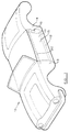
- a convertible vehicle body 10 has door aperture 11 at either side, each door aperture 11 being bounded along the bottom by a sill section 12 and forwardly and rearwardly by post sections 13 and 14. Doors 15 are hinged to the post section 13 and, when closed, a conventional lock 16 on each door releasably engages catch means on the post section 14.
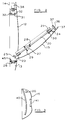
- a tie bar 20 is located in each of the doors 15, the tie bar 20 extending longitudinally of the vehicle and being mounted adjacent the upper edge of the door 15, through bush bearings 21 secured to the door 15.
- the tie bar 20 extends beyond the side edges 23 and 24 of the door 15.
- a spring 27 acts between a circlip 28 secured to the tie bar 20 and a bracket 29 attached to the door 15 to urge the tie bar 20 axially away from post section 13.
- a stop 30 is provided on the tie bar 20 and engages the bush bearing 21 adjacent edge 24 of door 15, to limit rearward movement of the tie bar 20.
- the end of the tie bar 20 remote from post section 13 has a head formation 36.
- the head formation 36 has a pair of diametrically opposed holes 37 formed therein, the axes of the holes 37 being parallel to the axis of the tie bar 20.
- a T-bar 25 of rectangular section is secured to the end of tie bar 20 adjacent post section 13.
- a bifurcated keeper plate 31 is provided on the post section 14, so that when the door is closed, the head formation 36 of the tie bar 20 will be located rearwardly of the keeper plate 31, the tie rod 20 passing between the bifurcated portions of the keeper plate 31.
- a pair of torsion pins 32 extend rearwardly from the keeper plate 31 in corresponding relationship to the holes 37 in the head formation 36.
- a solenoid controlled clamping plunger 38 is mounted rearwardly of the keeper plate 31 so that it is coaxial with the tie rod 20 when the door 15 is closed.
- the clamping plunger 28 is movable between a retracted position in which it is spaced rearwardly of the keeper plate 31 and an engaged position in which it is displaced towards the keeper plate 31.
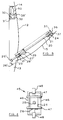
- a rectangular recess 26 corresponding to the T-bar 25 is provided in post section 13 and clamping means 45 as illustrated in detail in Figure 4 is provided to clamp the T-bar 25 in recess 26, when the door is closed.
- the clamping means 45 comprises a guide frame having a pair of vertically extending linear bearings 46 upon which are slidingly mounted a pair of clamping bars 47. Solenoid actuators 48 are provided for moving the clamping bars 47 between a retracted position in which they are clear of the recess 26 and a clamped position in which they overlay recess 26 and the T-bar 25 located therein.
- the tie bar 20 with head formation 36 and T-bar 25 are dimensioned such that when the door 15 is closed, the head formation 36 will locate between the keeper plate 31 and clamping plunger 38 clear of the torsion pins 32, the T-bar 25 being located in alignment with recess 26 but axially clear thereof.
- the clamping plunger 38 may then be energised to move it towards keeper plate 31 so that it engages the head formation 36 and moves the tie bar 20 axially forwards, so that torsion pins 32 engage in holes 37 and the T-bar 25 engages in the recess 26.
- the solenoid actuators 48 will then move clamping bars 47 so that they overlay the T-bar 25 and clamp it in the recess 26.
- the T-bar 25 may be tapered on its rearward face, so that the thickness thereof decreases away from the tie bar 20.
- the head formation 36 will be clamped between the plunger 38 and keeper plate 31 to transmit compressive and tensile loads therebetween while the torsion pins 32 engaging in holes 37 will transmit torsional load.
- the tie bar 20 will thereby transmit compressive, tensile and torsional loads from post section 13 to post section 14 thereby considerably improving torsional and bending stiffness of the vehicle body.
- the tie bar 20 will also improve the antiburst capability of the doors if the vehicle is involved in an accident.
- the clamping plunger 38 may be arranged to be energised upon closure of the door, for example by means of proximity or limit switches, while energisation of solenoid 30 may be controlled by means of a switch actuated when the T-bar 25 is located fully in recess 26. Alternatively, the clamping plunger 38 may be actuated upon starting of the engine or any other suitable operation. Furthermore, additional security from theft may be achieved by connecting the energising plunger 38 to the door locking system.
- the clamping means for the tie bar 20 may also serve as the catch means for securing the door 15 in its closed position.
- the tie bar 20 is biased towards post section 13 by means of a spring 27' engaging between circlip 28' on the tie bar 20 and bracket 29 secured to the door 15.
- the circlip 28' engages the bush bearing 21 adjacent edge 23 of the door 15, to limit forward movement of the tie bar 20.
- a T-bar 25' of D-section is secured to the end of tie bar 20 adjacent post section 13.
- a cylindrical seat 26' is provided on the post section 13 for engagement of T-bar 25', when the door is closed.
- the T-bar 25' is adapted to come into engagement with the seat 26' when the door is partially open and as the door is closed, the T-bar 25' will pivot with respect to the seat 26' gradually moving the tie bar 20 rearwardly against the spring 27'.
- the other end of the tie bar 20 is provided with a head formation 36 similar to that described above.
- the tie bar 20 will have been moved rearwardly sufficiently to bring the head formation 36 into engagement with the stop 38' mounted on the post section 14.
- the bifurcated keeper plate 31' with torsion pins 32 similar to those described above, is mounted on post section 14 forwardly of the stop 38', so that when the door 15 is closed and the head formation 36 engages stop 38', the keeper plate 31' and torsion pins 32 thereon, will be clear of the head formation 36.
- the keeper plate 31' is movable axially of the tie bar 20 when the door 15 is closed, towards stop 38' by means of a solenoid actuator 50, so that when the door 15 is closed the keeper plate 31' may be moved to clamp the head formation 36 and engage the torsion pins 32 in the holes 37 therein.
- the T-bar 25' may be clamped in the seat 26' in similar manner to that described above with reference to Figure 4.
- the tie bar 20 will thereby again be clamped when the door 15 is closed, so that it will transmit tensile, compressive and torsional loads between the post sections 13 and 14.
- the tie bar 20 may be fixed relative to the door 15, the end formations being arranged to engage complimentary formations when the door is closed and clamping means similar to those disclosed with reference to Figure 5 being used to provide clamping in tension, compression and torsion. Still further, formations similar to the end portions of the tie bar 20 may be secured to edges 23 and 24 of door 15 adjacent the upper edge thereof, the formations being adapted to be clamped in engagement with corresponding formations on the post sections 13 and 14, the door itself transmitting the tensile, compressive and torsional loads.
- the formations on the ends of the tie bar and complimentary formations on the post formations 13 and 24 may be varied as desired, provided that when in engagement they will transmit torsional loads.
- torsion pins are provided on the keeper plate to engage in holes of the head formation
- the pins may alternatively be provided on the head formation and holes in the keeper plate.
- any suitable clamping means may be used to clamp the complimentary formations in engagement when the door is closed. While in the above embodiments solenoid controlled clamping means are described, any suitable actuating mechanism, for example mechanical, electrical or pneumatic may be used.
- the tie bar 20 is located outboard of the door window 40 and will be fitted before the door window 40 and winder mechanism (not shown) are fitted. Alternatively, the tie bar 20 may be fitted inboard of the door window when it will be installed after the window and winder mechanism. It will be noted from Figure 3 that the tie bar 20 is in addition to conventional side intrusion reinforcement 41, which is not coupled to with the forward and rearward posts 13, 14 and cannot consequently transmit loads therebetween. The side intrusion reinforcement 41 is also sited near to the neutral axis of the vehicle.
- While the present invention will normally be applied to two or four door vehicles, it may be used for vehicles in which only one door is provided. Also while the invention is particularly applicable to convertible vehicles it may be used on vehicles with fixed roofs.
Landscapes
- Engineering & Computer Science (AREA)
- Mechanical Engineering (AREA)
- Lock And Its Accessories (AREA)
- Body Structure For Vehicles (AREA)
Applications Claiming Priority (2)
| Application Number | Priority Date | Filing Date | Title |
|---|---|---|---|
| GB9018350A GB9018350D0 (en) | 1990-08-21 | 1990-08-21 | Vehicle bodies |
| GB9018350 | 1990-08-21 |
Publications (2)
| Publication Number | Publication Date |
|---|---|
| EP0472284A1 true EP0472284A1 (de) | 1992-02-26 |
| EP0472284B1 EP0472284B1 (de) | 1994-09-07 |
Family
ID=10681005
Family Applications (1)
| Application Number | Title | Priority Date | Filing Date |
|---|---|---|---|
| EP19910306483 Expired - Lifetime EP0472284B1 (de) | 1990-08-21 | 1991-07-17 | Fahrzeugaufbauten |
Country Status (5)
| Country | Link |
|---|---|
| US (1) | US5224752A (de) |
| EP (1) | EP0472284B1 (de) |
| JP (1) | JPH04230476A (de) |
| DE (1) | DE69103848T2 (de) |
| GB (1) | GB9018350D0 (de) |
Cited By (10)
| Publication number | Priority date | Publication date | Assignee | Title |
|---|---|---|---|---|
| FR2698322A1 (fr) * | 1992-11-24 | 1994-05-27 | Renault | Porte de véhicule automobile à renfort de protection. |
| DE4342038A1 (de) * | 1993-12-09 | 1994-07-21 | Giok Djien Dr Ing Go | Fahrzeugtür bei PKW und LKW |
| EP0640504A1 (de) * | 1993-08-31 | 1995-03-01 | Automobiles Peugeot | Türverstärkung für Kraftfahrzeug |
| EP0718176A1 (de) * | 1994-12-22 | 1996-06-26 | MAN Nutzfahrzeuge Aktiengesellschaft | Kippbares Fahrerhaus eines Frontlenker-Lastkraftwagens |
| DE19615985C1 (de) * | 1996-04-22 | 1997-08-21 | Giok Djien Dr Ing Go | Bodengruppe eines Fahrzeuges mit Mitteln zur Erhöhung des Insassenschutzes |
| WO2000015454A1 (en) * | 1998-09-14 | 2000-03-23 | Joalto Design, Inc. | Vehicle closure panel having an intrusion beam as primary structure |
| WO2002034557A1 (fr) * | 2000-10-27 | 2002-05-02 | France Design | Dispositif de renforcement d'un vehicule notamment equipe d'un toit retractable |
| EP1043181A3 (de) * | 1999-04-05 | 2002-09-18 | General Motors Corporation | Fahrzeugkarosserie mit Seitenaufprall-Schutzvorrichtung |
| DE10223355B4 (de) * | 2002-05-25 | 2005-10-06 | Dr.Ing.H.C. F. Porsche Ag | Stoßauffangeinrichtung für Kraftfahrzeuge |
| DE10339310B4 (de) * | 2003-08-27 | 2006-02-09 | Dr.Ing.H.C. F. Porsche Ag | Tür für einen Aufbau eines Kraftfahrzeugs |
Families Citing this family (23)
| Publication number | Priority date | Publication date | Assignee | Title |
|---|---|---|---|---|
| US5378036A (en) * | 1992-07-13 | 1995-01-03 | Townsend; John A. | Sliding automobile door |
| ES2117416T3 (es) * | 1994-04-15 | 1998-08-01 | Steyr Daimler Puch Ag | Puerta de vehiculo con sistema de proteccion anticolision desmontable. |
| KR100204994B1 (ko) * | 1995-11-23 | 1999-06-15 | 정몽규 | 신장가능한 도어 임팩트 빔 |
| US5806917A (en) | 1995-12-22 | 1998-09-15 | Joalto Design, Inc. | Integrated motor vehicle door and chassis |
| US5908216A (en) * | 1995-12-22 | 1999-06-01 | Joalto Design, Inc. | Side intrusion beam with four points of connection |
| US6474725B2 (en) | 2000-07-26 | 2002-11-05 | Meritor Light Vehicle Technology, Llc | Reinforced cargo doors |
| US6601910B1 (en) * | 2002-05-31 | 2003-08-05 | Kevin G. Duggan | Expandable ram system |
| US6755460B1 (en) * | 2003-02-28 | 2004-06-29 | Paccar Inc. | Vehicle body panel mounting system |
| DE10341329B4 (de) * | 2003-09-08 | 2005-09-22 | Fraunhofer-Gesellschaft zur Förderung der angewandten Forschung e.V. | Vorrichtung und Verfahren zur Erhöhung des Insassenschutzes in einem Fahrzeug bei einem Seitenaufprall |
| US20050098371A1 (en) * | 2003-11-07 | 2005-05-12 | Zabtcioglu Fikret M. | Automotive post accident anti-entrapment system |
| KR100569962B1 (ko) * | 2004-04-08 | 2006-04-10 | 현대자동차주식회사 | 차량의 서지탱크 음압을 이용한 도어 임펙트빔 충격흡수구조 |
| TWM268630U (en) * | 2004-12-23 | 2005-06-21 | Inventec Corp | Clamping structure |
| JP4301271B2 (ja) * | 2006-09-12 | 2009-07-22 | 日産自動車株式会社 | 自動車の車体構造 |
| US7527321B1 (en) * | 2008-03-12 | 2009-05-05 | Ford Global Technologies, Llc | Static door catcher |
| US20100154308A1 (en) * | 2008-12-18 | 2010-06-24 | Venky Krishnan | Sliding door chucking and strengthening device |
| US8087714B2 (en) | 2010-03-11 | 2012-01-03 | Ford Global Technologies, Llc | Vehicle structural reinforcement system |
| DE102012025336A1 (de) * | 2012-12-21 | 2014-06-26 | Audi Ag | Fahrzeugschlosseinrichtung für ein Fahrzeug unter Verwendung einer Kupplungsvorrichtung |
| DE102013112775A1 (de) * | 2013-11-19 | 2015-05-21 | Dr. Ing. H.C. F. Porsche Aktiengesellschaft | Türanordnung |
| US9487066B1 (en) * | 2015-07-07 | 2016-11-08 | Toyota Motor Engineering & Manufacturing North America, Inc. | Deformable side impact bar |
| US10286761B1 (en) | 2016-06-06 | 2019-05-14 | Apple Inc. | Passenger vehicle door and window |
| US10309132B1 (en) * | 2016-06-16 | 2019-06-04 | Apple Inc. | Passenger vehicle and door structure |
| KR102868795B1 (ko) * | 2020-04-06 | 2025-10-10 | 현대자동차주식회사 | 차체 강성 보강기구 |
| US11420502B1 (en) * | 2021-02-25 | 2022-08-23 | Honda Motor Co., Ltd. | Door structure |
Citations (7)
| Publication number | Priority date | Publication date | Assignee | Title |
|---|---|---|---|---|
| DE2006498A1 (de) * | 1970-02-13 | 1971-09-02 | Adam Opel AG, 6090 Russeisheim | Vorrichtung zum Schutz der Insassen von Kraftfahrzeugen |
| DE2045875A1 (de) * | 1970-09-12 | 1972-03-16 | Volkswagenwerk Ag, 3180 Wolfsburg | Türanordnung für Straßenfahrzeuge |
| DE2254840A1 (de) * | 1971-11-29 | 1973-06-07 | Ford Werke Ag | Seitenschutz, insbesondere fuer kraftfahrzeuge |
| FR2198852A1 (de) * | 1972-09-14 | 1974-04-05 | Peugeot & Renault | |
| FR2207039A1 (de) * | 1972-11-17 | 1974-06-14 | Peugeot & Renault | |
| GB1365821A (en) * | 1971-06-04 | 1974-09-04 | Ford Motor Co | Vehicle door particulary for motor vehicles |
| GB2101535A (en) * | 1981-05-12 | 1983-01-19 | Bl Tech Ltd | Vehicle door |
Family Cites Families (8)
| Publication number | Priority date | Publication date | Assignee | Title |
|---|---|---|---|---|
| FR1260976A (fr) * | 1960-06-21 | 1961-05-12 | Armoire ou coffret réfrigérateur pour distribution contrôlée dans les hôtels ouautres | |
| GB1353738A (en) * | 1970-07-22 | 1974-05-22 | Chrysler Uk | Vehicle bodies |
| US3718364A (en) * | 1971-10-26 | 1973-02-27 | Gen Motors Corp | Vehicle body and frame construction |
| DE2836213A1 (de) * | 1978-08-18 | 1980-02-28 | Daimler Benz Ag | Seitenschutz fuer kraftwagen |
| GB2045331A (en) * | 1979-03-24 | 1980-10-29 | Hanlon E O | Bar Locking Mechanism |
| DE3512414A1 (de) * | 1985-04-04 | 1986-10-16 | Georg 8901 Königsbrunn Maurus | Vorrichtung zur herstellung einer festen, jedoch loesbaren verbindung zwischen zwei relativ zueinander bewegbaren teilen |
| US4940282A (en) * | 1985-10-03 | 1990-07-10 | Townsend John A | Chassis frame for a wheeled motor vehicle |
| US4743062A (en) * | 1986-09-19 | 1988-05-10 | The Dow Chemical Company | Vehicle door assembly |
-
1990
- 1990-08-21 GB GB9018350A patent/GB9018350D0/en active Pending
-
1991
- 1991-07-17 EP EP19910306483 patent/EP0472284B1/de not_active Expired - Lifetime
- 1991-07-17 DE DE69103848T patent/DE69103848T2/de not_active Expired - Fee Related
- 1991-07-31 US US07/738,333 patent/US5224752A/en not_active Expired - Fee Related
- 1991-08-20 JP JP3208223A patent/JPH04230476A/ja active Pending
Patent Citations (7)
| Publication number | Priority date | Publication date | Assignee | Title |
|---|---|---|---|---|
| DE2006498A1 (de) * | 1970-02-13 | 1971-09-02 | Adam Opel AG, 6090 Russeisheim | Vorrichtung zum Schutz der Insassen von Kraftfahrzeugen |
| DE2045875A1 (de) * | 1970-09-12 | 1972-03-16 | Volkswagenwerk Ag, 3180 Wolfsburg | Türanordnung für Straßenfahrzeuge |
| GB1365821A (en) * | 1971-06-04 | 1974-09-04 | Ford Motor Co | Vehicle door particulary for motor vehicles |
| DE2254840A1 (de) * | 1971-11-29 | 1973-06-07 | Ford Werke Ag | Seitenschutz, insbesondere fuer kraftfahrzeuge |
| FR2198852A1 (de) * | 1972-09-14 | 1974-04-05 | Peugeot & Renault | |
| FR2207039A1 (de) * | 1972-11-17 | 1974-06-14 | Peugeot & Renault | |
| GB2101535A (en) * | 1981-05-12 | 1983-01-19 | Bl Tech Ltd | Vehicle door |
Cited By (13)
| Publication number | Priority date | Publication date | Assignee | Title |
|---|---|---|---|---|
| FR2698322A1 (fr) * | 1992-11-24 | 1994-05-27 | Renault | Porte de véhicule automobile à renfort de protection. |
| EP0640504A1 (de) * | 1993-08-31 | 1995-03-01 | Automobiles Peugeot | Türverstärkung für Kraftfahrzeug |
| FR2709450A1 (fr) * | 1993-08-31 | 1995-03-10 | Peugeot | Renfort de porte pour véhicule automobile. |
| DE4342038A1 (de) * | 1993-12-09 | 1994-07-21 | Giok Djien Dr Ing Go | Fahrzeugtür bei PKW und LKW |
| EP0718176A1 (de) * | 1994-12-22 | 1996-06-26 | MAN Nutzfahrzeuge Aktiengesellschaft | Kippbares Fahrerhaus eines Frontlenker-Lastkraftwagens |
| US6196619B1 (en) | 1995-12-22 | 2001-03-06 | Joalto Design, Inc. | Vehicle closure panel having an intrusion beam as primary structure |
| DE19615985C1 (de) * | 1996-04-22 | 1997-08-21 | Giok Djien Dr Ing Go | Bodengruppe eines Fahrzeuges mit Mitteln zur Erhöhung des Insassenschutzes |
| WO2000015454A1 (en) * | 1998-09-14 | 2000-03-23 | Joalto Design, Inc. | Vehicle closure panel having an intrusion beam as primary structure |
| EP1043181A3 (de) * | 1999-04-05 | 2002-09-18 | General Motors Corporation | Fahrzeugkarosserie mit Seitenaufprall-Schutzvorrichtung |
| WO2002034557A1 (fr) * | 2000-10-27 | 2002-05-02 | France Design | Dispositif de renforcement d'un vehicule notamment equipe d'un toit retractable |
| FR2815925A1 (fr) * | 2000-10-27 | 2002-05-03 | France Design | Dispositif de renforcement d'un vehicule notamment equipe d'un toit retractable |
| DE10223355B4 (de) * | 2002-05-25 | 2005-10-06 | Dr.Ing.H.C. F. Porsche Ag | Stoßauffangeinrichtung für Kraftfahrzeuge |
| DE10339310B4 (de) * | 2003-08-27 | 2006-02-09 | Dr.Ing.H.C. F. Porsche Ag | Tür für einen Aufbau eines Kraftfahrzeugs |
Also Published As
| Publication number | Publication date |
|---|---|
| US5224752A (en) | 1993-07-06 |
| DE69103848T2 (de) | 1995-01-12 |
| GB9018350D0 (en) | 1990-10-03 |
| DE69103848D1 (de) | 1994-10-13 |
| EP0472284B1 (de) | 1994-09-07 |
| JPH04230476A (ja) | 1992-08-19 |
Similar Documents
| Publication | Publication Date | Title |
|---|---|---|
| EP0472284B1 (de) | Fahrzeugaufbauten | |
| US5944375A (en) | Movable roof construction for an open passenger car | |
| CA1290369C (en) | Vehicle door assembly | |
| JP2883631B2 (ja) | 自動車の扉組立体 | |
| DE60128882T2 (de) | Mittig schliessbare doppelt aufgehängte Türvorrichtung für Fahrzeuge | |
| US4850636A (en) | Cartridge assmebly for a vehicle door, a vehicle door shell and a door assembly | |
| US4629254A (en) | Motor vehicle seat | |
| US5772275A (en) | Apparatus and method for securing a convertible roof to an automobile vehicle | |
| US5306067A (en) | Rear door assembly for automobiles | |
| US5301987A (en) | Convertible top stack latch | |
| US20040056509A1 (en) | Door structure for vehicle | |
| EP1545919B1 (de) | Kraftfahrzeugkarosserie und kraftfahrzeug | |
| EP1449698B1 (de) | Vorrichtung für ein öffnungsfähiges Fahrzeugsdach | |
| US3749440A (en) | Tailgate | |
| WO2003059670A1 (en) | Vehicle door | |
| US7992925B2 (en) | Vehicle with improved double leafed door system | |
| US7559585B2 (en) | Support frame for header latch assembly | |
| EP1389547B1 (de) | Öffnungsfähiges Fahrzeugdach | |
| US12122223B2 (en) | Vehicle | |
| EP0709248B1 (de) | Kraftfahrzeugsitz mit einer nach vorn schwenkbaren Rückenlehne | |
| EP1254798B1 (de) | Einstellungsverfahren für eine Scharnier- und Verschlussvorrichtung eines Fahrzeuges | |
| US5718019A (en) | Hinge device | |
| DE60112070T2 (de) | An der dachverkleidung angebrachtes antriebssystem für eine fahrzeugheckklappe | |
| EP0342915A2 (de) | Türanlage | |
| DE19825919A1 (de) | Seitentür für eine selbsttragende Karosserie eines Kraftfahrzeugs |
Legal Events
| Date | Code | Title | Description |
|---|---|---|---|
| PUAI | Public reference made under article 153(3) epc to a published international application that has entered the european phase |
Free format text: ORIGINAL CODE: 0009012 |
|
| AK | Designated contracting states |
Kind code of ref document: A1 Designated state(s): DE FR GB IT SE |
|
| 17P | Request for examination filed |
Effective date: 19920805 |
|
| 17Q | First examination report despatched |
Effective date: 19931119 |
|
| GRAA | (expected) grant |
Free format text: ORIGINAL CODE: 0009210 |
|
| AK | Designated contracting states |
Kind code of ref document: B1 Designated state(s): DE FR GB IT SE |
|
| REF | Corresponds to: |
Ref document number: 69103848 Country of ref document: DE Date of ref document: 19941013 |
|
| ET | Fr: translation filed | ||
| ITF | It: translation for a ep patent filed | ||
| EAL | Se: european patent in force in sweden |
Ref document number: 91306483.8 |
|
| PGFP | Annual fee paid to national office [announced via postgrant information from national office to epo] |
Ref country code: SE Payment date: 19950619 Year of fee payment: 5 |
|
| PLBE | No opposition filed within time limit |
Free format text: ORIGINAL CODE: 0009261 |
|
| STAA | Information on the status of an ep patent application or granted ep patent |
Free format text: STATUS: NO OPPOSITION FILED WITHIN TIME LIMIT |
|
| 26N | No opposition filed | ||
| REG | Reference to a national code |
Ref country code: GB Ref legal event code: 746 Effective date: 19960614 |
|
| PG25 | Lapsed in a contracting state [announced via postgrant information from national office to epo] |
Ref country code: SE Effective date: 19960718 |
|
| REG | Reference to a national code |
Ref country code: FR Ref legal event code: D6 |
|
| EUG | Se: european patent has lapsed |
Ref document number: 91306483.8 |
|
| REG | Reference to a national code |
Ref country code: GB Ref legal event code: IF02 |
|
| PGFP | Annual fee paid to national office [announced via postgrant information from national office to epo] |
Ref country code: GB Payment date: 20030704 Year of fee payment: 13 |
|
| PGFP | Annual fee paid to national office [announced via postgrant information from national office to epo] |
Ref country code: DE Payment date: 20030710 Year of fee payment: 13 |
|
| PGFP | Annual fee paid to national office [announced via postgrant information from national office to epo] |
Ref country code: FR Payment date: 20030711 Year of fee payment: 13 |
|
| PG25 | Lapsed in a contracting state [announced via postgrant information from national office to epo] |
Ref country code: GB Free format text: LAPSE BECAUSE OF NON-PAYMENT OF DUE FEES Effective date: 20040717 |
|
| PG25 | Lapsed in a contracting state [announced via postgrant information from national office to epo] |
Ref country code: DE Free format text: LAPSE BECAUSE OF NON-PAYMENT OF DUE FEES Effective date: 20050201 |
|
| GBPC | Gb: european patent ceased through non-payment of renewal fee |
Effective date: 20040717 |
|
| PG25 | Lapsed in a contracting state [announced via postgrant information from national office to epo] |
Ref country code: FR Free format text: LAPSE BECAUSE OF NON-PAYMENT OF DUE FEES Effective date: 20050331 |
|
| REG | Reference to a national code |
Ref country code: FR Ref legal event code: ST |
|
| PG25 | Lapsed in a contracting state [announced via postgrant information from national office to epo] |
Ref country code: IT Free format text: LAPSE BECAUSE OF NON-PAYMENT OF DUE FEES;WARNING: LAPSES OF ITALIAN PATENTS WITH EFFECTIVE DATE BEFORE 2007 MAY HAVE OCCURRED AT ANY TIME BEFORE 2007. THE CORRECT EFFECTIVE DATE MAY BE DIFFERENT FROM THE ONE RECORDED. Effective date: 20050717 |