EP0472069B1 - Einbauanordnung eines Kollisionssensors für ein Kraftfahrzeug - Google Patents
Einbauanordnung eines Kollisionssensors für ein Kraftfahrzeug Download PDFInfo
- Publication number
- EP0472069B1 EP0472069B1 EP91113427A EP91113427A EP0472069B1 EP 0472069 B1 EP0472069 B1 EP 0472069B1 EP 91113427 A EP91113427 A EP 91113427A EP 91113427 A EP91113427 A EP 91113427A EP 0472069 B1 EP0472069 B1 EP 0472069B1
- Authority
- EP
- European Patent Office
- Prior art keywords
- front frame
- impact
- crash
- sensor
- vehicle body
- Prior art date
- Legal status (The legal status is an assumption and is not a legal conclusion. Google has not performed a legal analysis and makes no representation as to the accuracy of the status listed.)
- Expired - Lifetime
Links
- 230000001174 ascending effect Effects 0.000 claims description 3
- 230000003014 reinforcing effect Effects 0.000 description 16
- 230000004043 responsiveness Effects 0.000 description 13
- 239000011324 bead Substances 0.000 description 10
- 230000000694 effects Effects 0.000 description 9
- 230000001133 acceleration Effects 0.000 description 5
- 238000013016 damping Methods 0.000 description 3
- 230000033001 locomotion Effects 0.000 description 3
- 230000035945 sensitivity Effects 0.000 description 3
- 230000009466 transformation Effects 0.000 description 3
- 230000005540 biological transmission Effects 0.000 description 2
- 239000000725 suspension Substances 0.000 description 2
- 239000004020 conductor Substances 0.000 description 1
- 239000013078 crystal Substances 0.000 description 1
- 230000003247 decreasing effect Effects 0.000 description 1
- 230000001934 delay Effects 0.000 description 1
- 238000011161 development Methods 0.000 description 1
- 230000018109 developmental process Effects 0.000 description 1
- 230000005611 electricity Effects 0.000 description 1
- 238000002474 experimental method Methods 0.000 description 1
- 238000004519 manufacturing process Methods 0.000 description 1
- 238000000465 moulding Methods 0.000 description 1
- 230000002787 reinforcement Effects 0.000 description 1
- 238000003466 welding Methods 0.000 description 1
Images


Classifications
-
- B—PERFORMING OPERATIONS; TRANSPORTING
- B60—VEHICLES IN GENERAL
- B60R—VEHICLES, VEHICLE FITTINGS, OR VEHICLE PARTS, NOT OTHERWISE PROVIDED FOR
- B60R21/00—Arrangements or fittings on vehicles for protecting or preventing injuries to occupants or pedestrians in case of accidents or other traffic risks
- B60R21/01—Electrical circuits for triggering passive safety arrangements, e.g. airbags, safety belt tighteners, in case of vehicle accidents or impending vehicle accidents
- B60R21/013—Electrical circuits for triggering passive safety arrangements, e.g. airbags, safety belt tighteners, in case of vehicle accidents or impending vehicle accidents including means for detecting collisions, impending collisions or roll-over
- B60R21/0136—Electrical circuits for triggering passive safety arrangements, e.g. airbags, safety belt tighteners, in case of vehicle accidents or impending vehicle accidents including means for detecting collisions, impending collisions or roll-over responsive to actual contact with an obstacle, e.g. to vehicle deformation, bumper displacement or bumper velocity relative to the vehicle
-
- B—PERFORMING OPERATIONS; TRANSPORTING
- B60—VEHICLES IN GENERAL
- B60R—VEHICLES, VEHICLE FITTINGS, OR VEHICLE PARTS, NOT OTHERWISE PROVIDED FOR
- B60R21/00—Arrangements or fittings on vehicles for protecting or preventing injuries to occupants or pedestrians in case of accidents or other traffic risks
- B60R21/01—Electrical circuits for triggering passive safety arrangements, e.g. airbags, safety belt tighteners, in case of vehicle accidents or impending vehicle accidents
- B60R21/013—Electrical circuits for triggering passive safety arrangements, e.g. airbags, safety belt tighteners, in case of vehicle accidents or impending vehicle accidents including means for detecting collisions, impending collisions or roll-over
- B60R21/0132—Electrical circuits for triggering passive safety arrangements, e.g. airbags, safety belt tighteners, in case of vehicle accidents or impending vehicle accidents including means for detecting collisions, impending collisions or roll-over responsive to vehicle motion parameters, e.g. to vehicle longitudinal or transversal deceleration or speed value
Definitions
- the present invention relates to an impact-sensor mounting structure for an automotive vehicle and, more particularly, to a structure for mounting an impact sensor at a front portion of a vehicle body.
- the sensor system comprises a plurality of front sensors mounted in a so-called crash zone at the front portion of the vehicle body and one cowl sensor mounted to a cowl panel, etc. within the vehicle compartment.
- This sensor system is generally arranged in such a fashion that the cowl sensor is set to be highly sensitive while the front sensors are set to be less sensitive in order to prevent them from sensing too sensitive.
- the air bag system is provided with an AND circuit so arranged as to accept two signals indicative of a car crash from at least one of the front sensors and the cowl sensor and generate a signal for expanding the air bag.
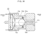
- reference numeral 10a denotes a sensing mass (a ball) made of a conductive material capable of sensing upon crash
- reference numeral 10b stands for a cylinder defining a passage for the sensing mass 10a
- reference numeral 10c denotes a terminal so arranged as to apply electricity as the sensing mass 10a rolls to come into abutment with the sensing mass 10a
- reference numeral 10d denotes a magnet so arranged as to hold the sensing mass 10a at the end portion of the cylinder 10b under normal circumstances.
- the responsiveness of the sensor system depends upon a roll of the sensing mass 10a.
- the axial direction of the sensing mass 10a is so arranged as to be perpendicular to a crash object, i.e. the direction in which the sensor system senses the crash is so set as to be horizontal with respect to the vehicle body.
- the front sensors of the conventional sensor system mounted at the front portion of the vehicle body cannot achieve high responsiveness particularly when the vehicle body is broken in the front portion thereof upon a crash and the directional property of the vehicle body is lost as the result of a deformation of the vehicle body.
- Japanese Patent Laid-open Publication (kokai) No. 50(1985)-141,045 discloses an impact sensor arranged so as to gain a constant degree of responsiveness within a particular range of angles by adapting the direction of sensing a crash by the impact sensor to the direction in which acceleration is caused to occur at a particular range of the angles due to the crash and by operating an equal degree of acceleration at any angle. Further, Japanese Utility Model Laid-open Publication (kokai) No.
- 2(1990)-10,159 discloses an impact sensor system whose forward mounting section is set to be more rigid than its rearward mounting section with the attempt to lose no directional property of the sensor itself even due to the deformation of the front portion of a front frame of the vehicle body upon a car crash, thereby avoiding a decrease in responsiveness.
- Fig. 2 of this document shows a sensor arranged between upper front beam and lower front beam of the motor vehicle.
- Figs. 5 - 7 show that during and after the crash the sensing direction is substantially horizontal.
- the document involves the manner in which rigidity is increased at the front mounting portion of the sensor in order to solve the problem that arises due to a delay in the timing of abutment of the ball to the switching portion by the forward movement of the ball by means of inertia on account of the transformation of the front mounting portion of the sensor, this transformation arising from the transformation of the front frame upon collision.
- Japanese Patent Laid-open Publication (kokai) No. 63(1988)-291,752 discloses an impact sensor which is mounted to the vehicle body in such a state that it descends forwards, thereby taking advantage of a vertical component of acceleration, which is caused to occur upon a severe crash, as well as a horizontal component of acceleration, in order to react against a crash with high sensitivity.
- the impact sensor disclosed in Japanese Patent Laid-open Publication No. 50-141,045 is so complex in structure that its production costs become too expensive and the impact sensor itself is pivotally disposed to sense an impact from a certain range of directions so that a wide space is required to cover the certain range of the directions.
- the impact sensor disclosed in Japanese Utility Model Laid-open Publication (kokai) No. 2-10,159 which corresponds to the preamble of claim 1, is said to be effective when a front frame of the vehicle body is compressed and crashed in the axial direction thereof, however, it does not present the great advantages if the front frame thereof would be compressed and deformed in an upward or downward direction as the result of a crash.
- the impact sensor disclosed in the Japanese Patent Laid-open Publication No. 63-291,752 is mounted to the vehicle body in a forwards descending manner in order to take advantage of the vertical component of acceleration.
- This prior patent publication is silent at all about an influence of deformation of the frame due to a car crash upon responsiveness of the impact sensor, so that it neither discloses nor implies whatsoever any idea of improving responsiveness of the impact sensor by paying attention to the deformation of the frame or the direction of input of external force upon crash of the vehicle body.
- GB-A-2 197 973 discloses the disposition of the air bag sensor to the tunnel portion or the like in which the steering wheel or the transmission is disposed.
- the sensor means detects crashes earlier and discriminates better when mounted at an angle to a horizontal plane passing through the horizontal axis of the vehicle so that it responds to both horizontal and vertical declaration compts.
- the sensor is preferably of the damped ball-in-tube type and the angular mounting thereof ranges from 10 to 40 degrees to the horizontal axis of the vehicle, with the forward end of the sensor lower than the rear.
- the sensor is alternatively a switch or a mass whose motion cots on electrical strain gauges or piezoelectric crystals.
- the sensor is preferably mounted away from the steering wheel column, e. g. in the transmission tunnel.
- a collision speed sensor device is attached to a motor vehicle in the rear of and adjacent to its front bumper. It comprises a stationary electromagnetic coil and a magnet responsive to the collision of the vehicle with an obstacle to pass through the coil to induce a voltage across the latter having a maximum value proportional to the speed of movement of the magnet or the collision speed of the vehicle.
- the maximum voltage in excess of a predetermined value serves to actuate a safety device of the air bag or auto-seat belt type disposed on the vehicle.
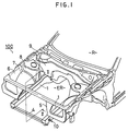
- Fig. 1 is a perspective view showing the front portion of a vehicle body to which the present invention is applied.
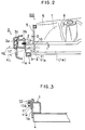
- Fig. 2 is a sectional view taken along line II-II of Fig. 1.
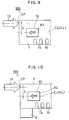
- Fig. 3 is a sectional view taken along line III-III of Fig. 2.
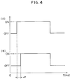
- Fig. 4 shows a time chart A showing responsiveness of the impact sensor to be attained by the front portion of the vehicle body to which a first embodiment of the present invention is applied and a time chart B showing responsiveness of the impact sensor to be attained by a conventional impact sensor disposed in a conventional and horizontal way at the front portion of the vehicle body which is arranged in substantially the same manner as in the first embodiment of the present invention.
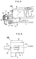
- Fig. 5 is a side view showing the front portion of the vehicle body to which a second embodiment of the present invention is applied.
- Fig. 6 is a schematic side view showing the front portion of the vehicle body to which a third embodiment of the present invention is applied.
- Fig. 7 is a schematic side view showing the front portion of the vehicle body to which a fourth embodiment of the present invention is applied.
- Fig. 8 is a schematic side view showing the front portion of the vehicle body to which a fifth embodiment of the present invention is applied.
- Fig. 9 is a schematic side view showing the front portion of the vehicle body to which a sixth embodiment of the present invention is applied.
- Fig. 10 is a schematic side view showing the front portion of the vehicle body to which a seventh embodiment of the present invention is applied.
- Fig. 11 is a schematic side view showing the front portion of the vehicle body to which an eighth embodiment of the present invention is applied.
- Fig. 12 is a schematic side view showing the front portion of the vehicle body to which a ninth embodiment of the present invention is applied.
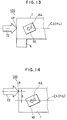
- Fig. 13 is a schematic side view showing the front portion of the vehicle body to which a tenth embodiment of the present invention is applied.
- Fig. 14 is a schematic side view showing the front portion of the vehicle body to which an eleventh embodiment of the present invention is applied.
- Fig. 15 is a perspective view showing part of the front portion of the vehicle body, when looked at from the obliquely forward position, to which a twelfth embodiment of the present invention is applied.
- Fig. 16 is a vertical view showing a sensor of a mass damping type as a representative example of the conventional impact sensors.
- Fig. 1 is a perspective view showing a front portion of the vehicle body to which the impact-sensor mounting structure according to the embodiment of the present invention is applied as well as Fig. 2 is a sectional view of the front portion of the vehicle body, when taken along line II-II of Fig. 1 and Fig. 3 is a sectional view of the front portion of the vehicle body, when taken along line III-III of Fig. 2.
- the front portion 100 has a pair of left-hand and right-hand front frames 1 extending in a longitudinal direction of the vehicle body and a bumper 3 is mounted through a stay 2 to a front end face of each of the front frames 1.
- the bumper 3 comprises a bumper face 3a, a bumper lane 3b and a buffer member 3c. Between the left-hand and right-hand front frames 1 is interposed a crossmember 4 which in turn is connected to a bottom face of each of the front frames 1.
- each front frame 1 To the front end portion of each front frame 1 is connected a shroud panel 5 which in turn is disposed extending in the transverse direction of the vehicle body and constituting a front wall of an engine room ER.
- the engine room ER has each of its side walls comprised of a wheel apron 6 which extends from the corresponding shroud panel 5 toward the rear portion of the engine room ER and whose lower end is connected to the corresponding front frame 1.
- the wheel apron 6 is provided with a wheel housing 7 projecting toward the inside of the engine room ER and a suspension tower 8 for supporting a suspension damper (not shown).
- a dash panel 9 which in turn extends over the entire width of the vehicle body as well as defines and divides the engine room ER from the vehicle compartment.
- the dash panel 9 constitutes a rear wall of the engine room ER.
- the front portion 100 of the vehicle body is provided with a front sensor (an impact sensor) 10 constituting the impact sensor system of an air bag system. More specifically, the front sensor 10 is of a mass damping type and is mounted to a side face of the front frame 1 at its front end portion on the external side of the vehicle body. It is noted herein that a conventional air bag to which the impact-sensor mounting structure according to the present invention is applied may be employed for the automotive vehicle, so that description and drawing thereof are omitted herefrom for brevity of explanation.
- the front sensor 10 is bolted through a bracket 11 to a central portion of an outer front frame 1a and the bracket 11 is bolted with a bolt 11a.
- the front sensor 10 is mounted to the outer front frame 1a at an angle of approximately 10° with respect to the horizontal line H.L. More specifically, the front sensor 10 is mounted in such an inclined manner that its front end is lower than its rear end and the axial line A.L of the cylinder 10b intersects the horizontal line H.L at the angle of approximately 10°. In other words, the direction in which the front sensor 10 senses the impact of the crash is inclined forwards at the angle of approximately 10°.
- the reason for mounting the front sensor 10 in the manner as inclined forwards at the angle of approximately 10° is because the front sensor 10 is caused to direct upwards due to the impact resulting from the crash and consequently it can sense the impact of the crash in the horizontal direction due to the fact that the front frame 1 is curved and deformed in its upward direction in the initial stage of the crash. This is caused to happen because the rigidity of the front frame 1 at its upper portion is weaker relative to the rigidity thereof at its lower portion due to the fact that the input point I.P of external force from the bumper 3, i.e.
- the central point of the bumper lane 3b is offset in an upward direction with the central point of the front frame 1 and further that the crossmember 4 connecting the left-hand and right-hand front frames 1 to each other is connected to the bottom face of the front frame 1 at its front end portion, thereby making the rigidity of the lower portion of the front frame 1 larger than that of the upper portion thereof.
- the front frame 1 is caused to be curved and deformed in the upward direction in the initial stage of the crash and thereafter it is compressed and deformed in its axial direction.
- direction of sensing the impact of a crash in a horizontal direction and relating terms are intended herein to mean the direction in which the sensing mass 10 disposed within the impact sensor 10a rolls over, i.e. the direction in which the axial line A.L of the cylinder 10b disposed within the impact sensor 10a extends.
- the direction in which the impact resulting from the crash is sensed is indicated by the arrow A.L as needed.
- the front sensor 10 is mounted in the forwards inclined manner because the direction of sensing the impact of the crash is set extending within the inside of the impact sensor 10 in the direction parallel to the direction in which a casing of the impact sensor 10 extends longitudinally. It can be noted, however, that the front sensor 10 may be mounted in the horizontal direction with respect to the vehicle body if the front sensor 10 is so arranged as for its direction of sensing the impact of the crash to be set in such a manner as inclined forwards at approximately 10° and as to achieve substantially the same effects as the front sensor 10 that is mounted to the front frame 10 in its forwards inclined arrangement at the angle of approximately 10°.
- the reference symbol A in Fig. 4 shows the time chart indicating the sensing time of the impact sensor that is mounted to set the direction A.L of sensing the impact at the angle of approximately 10° at which the impact sensor is inclined forwards.
- the reference symbol B in Fig. 4 shows the time chart indicating the sensing time of the impact sensor having the same structure as in this embodiment, that is mounted in the horizontal direction as in conventional manner, i.e. in such a fashion that the direction A.L of the impact sensor 10 in sensing the impact of the crash is set parallel to the longitudinally horizontal line of the vehicle body.
- the vertical axis indicates the sensing state
- the horizontal axis indicates the period of time expressed in ms.
- the impact sensor 10 mounted in the conventional way delays sensing the impact resulting from the crash by the period of time, ⁇ T, from the time when the impact sensor 10 mounted in the manner as in this embodiment of the present invention, as indicated by the reference symbol A in Fig. 4.
- the front end portion of the front frame 1 is caused to be curved and deformed in the upward direction at the initial stage of the crash so that the direction A.L of sensing the impact of the crash by the impact sensor 10 mounted in the manner as in the embodiment of the present invention is allowed to approach to the horizontal line H.L as the front end portion of the front frame 10 is caused to be curved upwards at the initial stage of the crash, i.e. that the direction A.L of sensing the impact is changed so as to achieve the desired extent of sensitivity.
- the direction A.L of sensing the impact resulting from the crash is caused to be remote from the horizontal line H.L, i.e. the direction A.L is changed so as to make the sensitivity to the impact less sensitive.
- the angle at which the impact sensor is inclined forwards is set to approximately 10° as a result of experiments, however, the angle at which the impact sensor 10 is arranged for its direction A.L for sensing the impact of the crash to be set substantially horizontal upon the crash is not restricted to the 10° angle and may vary with models of the automotive vehicle, such as the input point of external force from the bumper 3 upon the crash, the difference in rigidity between the upper and lower portions of the front frame 10, etc.
- the impact sensor 10 may be mounted at the angle at which the impact sensor 10 is inclined forwards greater than the 10° angle.
- the impact sensor 10 may be inclined forwards at the angle smaller than the 10° angle.
- the front portion 100 of the vehicle body in this structure has basically the same structure as that in the first embodiment of the present invention as described hereinabove.
- the crossmember 4 is joined to the bottom face of the front frame 1 and the input point I.P of input of the impact resulting from the crash is offset upwards by the distance, ⁇ , with respect to the longitudinally central line C.L (the horizontal line H.L, too) of the front frame 1.
- the front end portion of the front frame 1 is caused to be curved and deformed toward the upward direction in the initial stage of the crash.
- a reinforcing plate 12 is joined to an upper front end portion of the front frame 1, i.e. to an inner face of the upper wall of the front frame 1 in a sectionally closed structure, and this reinforcing plate 12 serves as suppressing the front end portion of the front frame 1 from curving in the upward direction in the initial stage of the crash.
- the front portion 100 of the vehicle body in this structure is arranged that the front frame 1 is caused to be compressed and deformed in its axial direction without causing any substantial curvature in the upward or downward direction due to the reinforcement by the reinforcing plate 12.
- the impact sensor 10 is so mounted as for its sensing direction A.L to be arranged in or along the longitudinally central line C.L (i.e. the horizontal line H.L) of the front frame 10.
- the impact sensor 10 disposed in or along the horizontal line H.L of the vehicle body is allowed for its sensing direction A.L to be maintained in the horizontal direction even prior to or subsequent to the crash, thereby permitting a desired extent of responsiveness to be attained.
- the arrow 13 is intended to mean the input point of input of the external force from the bumper 3, i.e. the input point I.P of input of the impact load resulting from the crash toward the front frame 1.
- the input point I.P of input of the impact resulting from the crash is not offset with respect to the longitudinally central line C.L of the front frame 1, however, the crossmember 4 is disposed at the lower front end portion of the front frame 1 and a reinforcing member, such as the reinforcing plate 12 or the like, is joined to the upper front end portion of the front frame 1.
- a reinforcing member such as the reinforcing plate 12 or the like
- the front portion of the front frame 1 may be constructed such that the cross member 4 is disposed at the upper portion of the front frame 1 while the reinforcing member 12 is disposed at the lower portion thereof. In this case, too, the same effect as described hereinabove can be achieved.
- a plurality of concave beads 14 are disposed at a position behind the crossmember 4 mounted to the lower front portion of the front frame 1, in place of the reinforcing plate 12 used in the third embodiment of the present invention.
- the beads 14 are disposed on the both side walls of the front frame 1 and formed each in a concave shape extending upwards, thereby decreasing the strength of the front frame 1 at its lower portion in the longitudinal direction of the vehicle body so as to keep balance in rigidity between the upper and lower portions of the front frame 1.
- the front frame 1 is caused to be crashed and deformed in its axial direction and the impact sensor 10 can maintain its sensing direction A.L to be substantially horizontal upon the crash in substantially the same manner as in the structure according to figure 5.
- the front frame 1 may be constructed in the manner opposite to the disposition of the plural beads 14 as in the structure described immediately hereinabove, i.e. the disposition of the beads 14 at the upper portion of the front frame 1, to thereby reduce the strength at the upper portion of the front frame 1.
- This arrangement can achieve the same effect as the arrangement for the beads to be disposed at the lower portion of the front frame 1 as in the first part of the structure as in figure 7 as described immediately hereinabove.
- This embodiment can likewise achieve the same effects.
- the front portion of the front frame 1 is caused to be curved and deformed in the upward direction upon the crash. Accordingly, the sensing direction A.L of the impact sensor 10 is caused to direct toward the upward direction, too, as the front portion of the front frame 1 is crashed upwards, when the impact sensor 10 is mounted in the horizontal position relative to the vehicle body.
- a reinforcing plate 12 or any other reinforcing member is fixed at the upper front end portion of the front frame 1 to thereby reinforce the rigidity at the upper front end portion of the front frame 1 and suppress the front frame 1 at its front end portion from curving and deforming in its upward direction.
- This structure of the front frame 1 is allowed that it is crashed and deformed in its axial direction without any substantial deformation in the upward and downward directions in substantially the same manner as in the structure according to figure 5 as described hereinabove and the impact sensor 10 can be operated so as to sense the impact of the crash in its horizontal direction.
- the impact resulting from the crash is offset by the distance, ⁇ , with respect to the longitudinally central line C.L of the front frame 1 even if the force of impact is entered in the position remote by the distance ⁇ from the longitudinally central line C.L thereof, thereby allowing the impact sensor 10 to keep its horizontally sensing direction A.L upon the crash.
- the input point I.P of input of the impact resulting from the crash may be set at the lower portion of the front frame 1, opposite to the structure according to figure 8 as described immediately hereinabove, i.e. the input point I.P is offset downwards by the distance ⁇ with respect to the center line C.L of the front frame 1.
- the reinforcing plate 12 or other reinforcing member may be disposed at the lower portion of the front frame 1, in the manner opposite to the structure described immediately hereinabove.
- the input point I.P of input of the impact resulting from the crash is offset upwards by the distance ⁇ with respect to the longitudinally central line C.L so that this arrangement enables the impact sensor 10 to keep a horizontally sensing direction A.L.
- the concave beads 14 may be disposed at the upper portion of the front frame 1 as the means for slightly reducing rigidity of the front frame, thereby reducing the rigidity at the upper portion of the front frame 1 to a slight extent and allowing the impact sensor 10 to sense its direction A.L at a horizontal level in the manner opposite to the arrangement in the structure described immediately hereinabove.
- This structure can achieve the same effects as in the first part of the structure according to figure 9 as described hereinabove.
- the front portion 100 of the vehicle body as employed in the second embodiment above in which, in place of the reinforcing plate 12, a plurality of the beads 14 as disposed in the position behind the crossmember 4 disposed at the lower front end portion of the front frame 1, thereby reducing the rigidity at the lower portion of the front frame 1 and deforming the front frame 1 in its parallel axial direction upon the crash.
- This allows the impact sensor 10 to keep its sensing direction A.L in a substantially horizontal fashion when the front frame 1 is caused to be crashed and deformed in its axial direction as a result of the crash.
- the plural beads 14 may be disposed in the manner opposite to the arrangement of the plural beads 14 in the structure according to figure 10 as described hereinabove. In this case, the same effects can be achieved by this structure as described in the first part of this structure according to figure 10
- the cross member 4 is disposed at the lower front end portion of the front frame 1 so as to raise the rigidity at its lower portion to an extent higher than at its upper portion and, as a consequence, to set the input point of input of the external force from the bumper 3 resulting from the crash, i.e. the input point I.P of input of the impact of the crash, to a lower portion of the front frame 1.
- the input point I.P of the input of the impact resulting from the crash is offset downwards by the distance ⁇ with the longitudinally central line C.L of the front frame 1.
- This arrangement causes the front frame 1 to be crashed and deformed in its axial direction in substantially the same manner as in the structure according to figure 5 as described hereinabove and allows the impact sensor 10 to sense the direction A.L for sensing the input of the impact of the crash in a substantially horizontal direction.
- the cross member 4 may be disposed at the upper front end portion of the front frame 1 to thereby elevate the rigidity at the upper portion of the front frame 1 to a level higher than that at the lower portion thereof, in the manner opposite to the structure described immediately hereinabove. This arrangement can likewise achieve the same effect.
- the front portion 100 of the vehicle body according to figure 12 of the present invention has no difference in rigidity between at its upper and lower portions from the longitudinally central line C.L of the front frame 1, so that the front portion of the front frame 1 is crashed and deformed in its axial direction without causing the front portion of the front frame 1 to be curved and deformed in an upward direction or in a downward direction.
- the impact sensor 10 is mounted to the front frame 1 so as to allow the input point I.P of input of the impact of the crash to agree with the longitudinally central line H.L of the front frame 1. This arrangement allows the impact sensor 10 to keep its sensing direction in a horizontal state upon the crash.
- the input point 13 of input of external force from the bumper i.e. the input point I.P of input of the impact upon the crash
- the input point is arranged so as to coincide with the longitudinally central line C.L of the front frame 1, however, the input point is not offset in neither of the upward direction nor the downward direction, as shown in Fig. 13.
- the crossmember 4 To the bottom face of the front end portion of the front frame 1 is joined the crossmember 4, thereby allowing the rigidity et the lower portion of the front frame 1 to be set higher relative to that at the upper portion thereof.
- the impact sensor 10 is mounted in such a state that it is descending forwards in substantially the same manner as in the first embodiment as described hereinabove.
- This structure causes the front end portion of the front frame 1 to be curved and deformed in its upward direction in the initial stage of the crash and allows the impact sensor 10 to approach its sensing direction A.L to the horizontal line H Z of the front frame 1 as the front end portion of the front frame 10 is caused to be curved and deformed toward the upward direction.
- the second embodiment may be arranged such that the structure of the front end portion of the front frame 1 is opposite to the structure thereof in the second embodiment as described immediately hereinabove.
- This arrangement causes the front end portion of the front frame 1 to be curved and deformed in its downward direction in the initial stage of the crash, so that the disposition of the impact sensor 10 in the forwards ascending manner is effective for keeping the sensing direction A.L of the impact sensor 10 to a horizontal level in the initial stage of the crash.
- the rigidity at the upper portion of the front frame 1 is set equal to that at the lower portion thereof.
- the input point 13 of input of the external force from the bumper i.e. the input point I.P of input of the impact resulting from the crash, is offset upwards by the distance ⁇ with respect to the longitudinally central line C.L of the front frame 1.
- the impact sensor 10 is mounted in such a manner as inclined forwards in substantially the same manner as in the first embodiment as described hereinabove, so that the impact sensor 10 is caused to move so as to allow its sensing direction A.L to approach to and coincide with the longitudinally central line C.L of the front frame 10, i.e. the horizontal line H.L of the vehicle body, due to the curvature of the front frame 1 toward the upward direction in the initial stage of the crash.
- This embodiment may be modified in such a manner that the input point of input of the external force from the bumper, i.e. the input point I.P of input of the impact resulting from the crash, is offset downwards by the distance ⁇ with respect to the longitudinally central line C.L of the front frame 1 and the impact sensor 10 is mounted in such a manner as ascending forwards.
- This arrangement can also achieve the effect as in the first part of the third embodiment as described immediately hereinabove.
- a side portion of the shroud panel 5 comprises a shroud side panel 5a and a shroud upper panel 5b joined to an upper end of the shroud side panel 5a.
- To a lower end of the shroud side panel 5a is joined the cross member 4.
- the shroud panel 5 and the crossmember 4 serve as a member for reinforcing the vehicle body, and a vertically open space 5c is provided between the shroud upper panel 5b and the crossmember 4, and the open space 5c is defined additionally by a central section 5d located on the central side of the vehicle body and a side section 5e located on the outer side thereof.
- the shroud upper panel 5b is in such a shape as its transverse end portion being curved gradually rearward and the shroud side panel 5a is so arranged that its side section 5e is located in the position behind the central section 5d.
- the front frame 1 is located in the position closer to the central section 5d of the shroud side panel 5a and in a virtually intermediate position of the open space 5c between the crossmember and the shroud upper panel 5b. And the front end portion of the front frame 1 is so arranged as to pass through the open space 5c and to project in a forward direction.
- an L-shaped bracket 16 in a transverse cross-section, which has two holes 17 disposed in a vertically spaced relationship, and the bumper (not shown) is fastened to the L-shaped bracket 16 with bolts through the holes 17.
- the front frame 1 is disposed at its front end portion to be integral with the shroud side panel 8a through a connecting panel 18 that in turn is generally formed by press molding, for example, in a nearly square C-letter shape in its transverse cross-section having an opening facing in a rearward direction.
- the connecting panel 18 comprises a front end wall section 18a disposed in abutment with the front end face of the front frame 1 and extending in a transverse direction of the vehicle body, an inner wall section 18b extending toward the rearward direction from the end on the central side of the front end wall section 8a to the side face on the inner side of the front frame 1, and an outer side wall section 18c extending toward the rearward direction in a relationship spaced apart from the outer front frame panel 1a of the front frame 1.
- Each of the sections 18a to 18c is disposed in such a shape as extending up to the lower end of the shroud side panel 5a.
- the connecting panel 18 has a portion of its side wall section 18b connected to the front frame 1 and the rear end of the outer wall section 18c is to connected to the shroud side panel 5a (the side section 5e), while the bottom end of the connecting panel 18 is connected to the bottom end of the shroud side panel 5a.
- the symbol "x" indicates a site for welding.
- this structure may be modified such that the impact sensor 10 may be mounted on the outer front frame section 1a.
Landscapes
- Engineering & Computer Science (AREA)
- Mechanical Engineering (AREA)
- Body Structure For Vehicles (AREA)
- Air Bags (AREA)
Claims (6)
- Einbauanordnung eines Kollisionssensors für ein Kraftfahrzeug, bei der ein Kollisionssensor (10) zur Erfassung der Wucht einer Kollision am vorderen Endabschnitt eines Frontholms (1), an dessen vorderem Ende eine Stoßstange (3) befestigt ist, so angebracht ist, daß er sich in Längsrichtung der Fahrzeugkarosserie erstreckt, wobei der Frontholm (1) die Eigenschaft aufweist, sich in der Anfangsphase der Kollision ausgehend vom Angriffspunkt der Stoßkraft, die über die Stoßstange (3) auf den Frontholm (1) übertragen wird, in Aufwärtsrichtung oder Abwärtsrichtung zu verbiegen und zu verformen,
dadurch gekennzeichnet,daß der Kollisionssensor (10) in bezug auf eine Horizontale mit Vorwärtsneigung am Frontholin (1) angebracht ist, so daß die Ansprechrichtung (A.L) des Kollisionssensors (10) in der Anfangsphase der Kollision im wesentlichen horizontal wird, wenn der Frontholm (1) die Eigenschaft aufweist, sich durch die Wucht einer Kollision in Aufwärtsrichtung zu verbiegen und zu verformen, und daß der Kollisionssensor (10) in bezug auf eine Horizontale mit Rückwärtsneigung am Frontholin (1) angebracht ist, so daß die Ansprechrichtung (A.L) des Kollisionssensors (10) in der Anfangsphase der Kollision im wesentlichen horizontal wird, wenn der Frontholm (1) die Eigenschaft aufweist, sich durch die Wucht einer Kollision in Abwärtsrichtung zu verbiegen und zu verformen. - Einbauanordnung eines Kollisionssensors nach Anspruch 1, bei der der Angriffspunkt (I.P.) der Stoßkraft auf der Längsachse (C.L.) des Frontholms (1) liegt und an der Ober- oder Unterseite des Frontholms (1) eine Querstrebe (4) befestigt ist, die sich in Querrichtung der Fahrzeugkarosserie erstreckt.
- Einbauanordnung eines Kollisionssensors nach Anspruch 1, bei der der Angriffspunkt (I.P.) der Stoßkraft gegen die Längsachse (C.L.) des Frontholms (1) um einen vorgegebenen Abstand (δ) nach oben oder unten versetzt ist.
- Einbauanordnung eines Kollisionssensors nach Anspruch 1, bei der an der Ober- oder Unterseite des Frontholnis (1) eine Querstrebe (4) befestigt ist, die sich in Querrichtung der Fahrzeugkarosserie erstreckt, der Angriffspunkt (I.P.) der Stoßkraft gegen die Längsachse (C.L.) des Frontholms (1) um einen vorgegebenen Abstand (δ) nach oben oder unten versetzt ist und der Frontholin (1) so angeordnet ist, daß er in der Richtung, in der der Angriffspunkt (I.P.) der Stoßkraft um den vorgegebenen Abstand (δ) versetzt ist, verbogen und verformt wird.
- Einbauanordnung eines Kollisionssensors nach einem der Ansprüche 1 bis 4, dadurch gekennzeichnet, daß- sich der Frontholm (1) in Längsrichtung der Fahrzeugkarosserie erstreckt,- der vordere Teil der Fahrzeugkarosserie ein sich in deren Querrichtung erstreckendes Abdeckblech (5) und ein Verbindungsblech (18), das den Frontholm (1) mit dem Abdeckblech (5) verbindet, umfaßt,wobei der vordere Endabschnitt des Frontholms (1) über das Abdeckblech (5) hinaus nach vorn ragt, so daß sein vorderes Ende eine Montagefläche für die Stoßstange (3) bilden kann, und
das Verbindungsblech (18) einen stirnseitigen Abschnitt (18a) umfaßt, der an der Montagefläche des Frontholms (1) anliegt und zwischen der Montagefläche und der Stoßstange (3) angeordnet ist, so daß ein Teil der Stoßkraft, die über die Stoßstange (3) auf das Verbindungsblech (18) einwirkt, auf den Frontholin (1) übertragen wird, wodurch die Verformung infolge eines durch die Kollision verursachten Nach-oben- oder Nach-unten-Verbiegens eingeschränkt wird, und- der Kollisionssensor (10) so am Frontholm (1) oder am Verbindungsblech (18) angebracht ist, daß die Ansprechrichtung (A.L) des Kollisionssensors (10) zur Erfassung der Wucht der Kollision im wesentlichen horizontal wird. - Einbauanordnung eines Kollisionssensors nach Anspruch 5, bei der das Verbindungsblech (18) einen Seitenwandabschnitt (18c) aufweist, der sich in Längsrichtung der Fahrzeugkarosserie erstreckt und in einem bestimmten Abstand zum Frontholm (1) angeordnet ist, und der Kollisionssensor (10) am Seitenwandabschnitt (18c) angebracht ist.
Applications Claiming Priority (6)
| Application Number | Priority Date | Filing Date | Title |
|---|---|---|---|
| JP21202290 | 1990-08-09 | ||
| JP212022/90 | 1990-08-09 | ||
| JP9629/91 | 1991-01-30 | ||
| JP962991 | 1991-01-30 | ||
| JP198570/91 | 1991-07-12 | ||
| JP3198570A JP2983704B2 (ja) | 1990-08-09 | 1991-07-12 | 車両の衝突センサ取り付け構造 |
Publications (3)
| Publication Number | Publication Date |
|---|---|
| EP0472069A2 EP0472069A2 (de) | 1992-02-26 |
| EP0472069A3 EP0472069A3 (en) | 1992-04-01 |
| EP0472069B1 true EP0472069B1 (de) | 1997-05-02 |
Family
ID=27278567
Family Applications (1)
| Application Number | Title | Priority Date | Filing Date |
|---|---|---|---|
| EP91113427A Expired - Lifetime EP0472069B1 (de) | 1990-08-09 | 1991-08-09 | Einbauanordnung eines Kollisionssensors für ein Kraftfahrzeug |
Country Status (5)
| Country | Link |
|---|---|
| US (1) | US5364158A (de) |
| EP (1) | EP0472069B1 (de) |
| JP (1) | JP2983704B2 (de) |
| KR (1) | KR960002425B1 (de) |
| DE (1) | DE69125893T2 (de) |
Families Citing this family (26)
| Publication number | Priority date | Publication date | Assignee | Title |
|---|---|---|---|---|
| JPH05112196A (ja) * | 1991-06-25 | 1993-05-07 | Mazda Motor Corp | 自動車用エアバツグセンサーの取付構造 |
| JPH08164869A (ja) * | 1994-12-15 | 1996-06-25 | Fuji Heavy Ind Ltd | 車両の前部フレーム構造 |
| US5580084A (en) * | 1995-09-12 | 1996-12-03 | Artistic Analytical Methods, Inc. | System and method for controlling vehicle safety device |
| US5863467A (en) * | 1996-05-03 | 1999-01-26 | Advanced Ceramics Corporation | High thermal conductivity composite and method |
| JPH1016702A (ja) * | 1996-06-30 | 1998-01-20 | Isuzu Motors Ltd | 車両の衝突センサー取付装置 |
| JP3407549B2 (ja) * | 1996-07-10 | 2003-05-19 | トヨタ自動車株式会社 | 側面衝突用センサの取付構造 |
| WO1998042542A2 (de) * | 1997-03-20 | 1998-10-01 | Siemens Aktiengesellschaft | Anordnung zum steuern einer sicherheitseinrichtung zum aufprallschutz in einem fahrzeug |
| DE19745309A1 (de) * | 1997-10-14 | 1999-04-22 | Telefunken Microelectron | Unfall-Sensor |
| US6019419A (en) * | 1997-12-19 | 2000-02-01 | General Motors Corporation | Vehicle rail crush control system and method |
| FR2792899B1 (fr) * | 1999-04-30 | 2001-06-15 | Plastic Omnium Cie | Dispositif de fixation d'un capteur de positionnement et piece de carrosserie munie d'un tel dispositif |
| ATE238189T1 (de) * | 1999-10-06 | 2003-05-15 | Alcan Tech & Man Ag | Anordnung zur absorption von aufprallenergie |
| US6712426B2 (en) * | 2001-10-17 | 2004-03-30 | Textron Automotive Company, Inc. | Motor vehicle front end structure |
| JP4306229B2 (ja) * | 2002-04-03 | 2009-07-29 | タカタ株式会社 | 衝突検出装置及び安全装置 |
| JP4403719B2 (ja) * | 2003-05-12 | 2010-01-27 | トヨタ自動車株式会社 | 車両、及び乗員保護装置の起動制御装置 |
| JP3930004B2 (ja) * | 2004-08-27 | 2007-06-13 | 本田技研工業株式会社 | センサ配設構造 |
| JP2006282049A (ja) * | 2005-04-01 | 2006-10-19 | Denso Corp | 車両用衝突物判定装置 |
| JP4121529B2 (ja) * | 2006-04-20 | 2008-07-23 | 本田技研工業株式会社 | 車体前部構造 |
| KR100911388B1 (ko) * | 2007-11-16 | 2009-08-07 | 현대자동차주식회사 | 차량의 후방 검사장치 |
| JP5272749B2 (ja) * | 2009-01-23 | 2013-08-28 | トヨタ自動車株式会社 | サスペンションタワー |
| WO2010143253A1 (ja) * | 2009-06-08 | 2010-12-16 | トヨタ自動車株式会社 | 車両及び衝突検出装置 |
| US8398133B2 (en) * | 2010-10-28 | 2013-03-19 | Ford Global Technologies, Llc | Pressure-based crash detection system incorporated in side rail |
| KR20140023048A (ko) * | 2012-08-16 | 2014-02-26 | 현대자동차주식회사 | 액티브 후드 시스템의 충격감지센서 |
| US9260072B2 (en) * | 2014-03-26 | 2016-02-16 | Ford Global Technologies, Llc | Pedestrian protection sensing system for vehicle having metal bumpers |
| JP6790342B2 (ja) * | 2015-10-02 | 2020-11-25 | トヨタ自動車株式会社 | 車両用センサの取り付け構造 |
| JP6645292B2 (ja) * | 2016-03-18 | 2020-02-14 | 三菱自動車工業株式会社 | センサ取付構造 |
| JP6344424B2 (ja) | 2016-04-19 | 2018-06-20 | トヨタ自動車株式会社 | 周辺情報検出センサの取付構造 |
Citations (1)
| Publication number | Priority date | Publication date | Assignee | Title |
|---|---|---|---|---|
| JPH0210159U (de) * | 1988-07-05 | 1990-01-23 |
Family Cites Families (15)
| Publication number | Priority date | Publication date | Assignee | Title |
|---|---|---|---|---|
| US3859482A (en) * | 1971-03-04 | 1975-01-07 | Nissan Motor | Mechanical pressure detecting device |
| US3861488A (en) * | 1971-03-08 | 1975-01-21 | Mitsubishi Electric Corp | Collision speed sensor |
| US3718332A (en) * | 1971-08-27 | 1973-02-27 | Gen Motors Corp | Occupant restraint system |
| US3718364A (en) * | 1971-10-26 | 1973-02-27 | Gen Motors Corp | Vehicle body and frame construction |
| AU458138B2 (en) * | 1971-11-30 | 1975-02-20 | Nissan Motor Company Limited | Collision sensor for vehicle safety device |
| DE2211560A1 (de) * | 1972-03-10 | 1973-09-13 | Daimler Benz Ag | Anordnung einer stossfangeinrichtung eines fahrzeuges, insbesondere eines personenkraftwagens |
| DE2233972A1 (de) * | 1972-07-11 | 1974-01-31 | Volkswagenwerk Ag | Stossfaengeranordnung, insbesondere fuer ein kraftfahrzeug |
| US3862669A (en) * | 1972-11-24 | 1975-01-28 | Gen Motors Corp | Occupant restraint system |
| FR2208371A5 (de) * | 1972-11-28 | 1974-06-21 | Citroen Sa | |
| JPS6042067B2 (ja) * | 1980-06-13 | 1985-09-20 | マツダ株式会社 | 自動車の車体前部構造 |
| DE3617099A1 (de) * | 1986-05-21 | 1987-11-26 | Bayerische Motoren Werke Ag | Nachgiebige anordnung eines stossfaengers am aufbau eines kraftfahrzeugs |
| US4819960A (en) * | 1986-11-21 | 1989-04-11 | Breed Automotive Technology, Inc. | Angled vehicle crash sensor |
| DE3717427C3 (de) * | 1987-05-23 | 1994-09-01 | Deutsche Aerospace | Aufprallsensor für Kraftfahrzeuge |
| JP2595724B2 (ja) * | 1989-08-30 | 1997-04-02 | 日産自動車株式会社 | 強度部材の製造方法 |
| EP0449241B1 (de) * | 1990-03-30 | 1994-11-09 | Mazda Motor Corporation | Vorderwagenaufbau eines Kraftfahrzeuges |
-
1991
- 1991-07-12 JP JP3198570A patent/JP2983704B2/ja not_active Expired - Fee Related
- 1991-08-09 DE DE69125893T patent/DE69125893T2/de not_active Expired - Fee Related
- 1991-08-09 KR KR1019910013767A patent/KR960002425B1/ko not_active Expired - Fee Related
- 1991-08-09 EP EP91113427A patent/EP0472069B1/de not_active Expired - Lifetime
-
1993
- 1993-08-12 US US08/104,939 patent/US5364158A/en not_active Expired - Fee Related
Patent Citations (1)
| Publication number | Priority date | Publication date | Assignee | Title |
|---|---|---|---|---|
| JPH0210159U (de) * | 1988-07-05 | 1990-01-23 |
Also Published As
| Publication number | Publication date |
|---|---|
| DE69125893T2 (de) | 1997-08-14 |
| DE69125893D1 (de) | 1997-06-05 |
| JP2983704B2 (ja) | 1999-11-29 |
| JPH04297353A (ja) | 1992-10-21 |
| US5364158A (en) | 1994-11-15 |
| KR960002425B1 (ko) | 1996-02-17 |
| EP0472069A2 (de) | 1992-02-26 |
| KR920004211A (ko) | 1992-03-27 |
| EP0472069A3 (en) | 1992-04-01 |
Similar Documents
| Publication | Publication Date | Title |
|---|---|---|
| EP0472069B1 (de) | Einbauanordnung eines Kollisionssensors für ein Kraftfahrzeug | |
| EP0807559B1 (de) | Aufprall-Sensorvorrichtung | |
| EP1577196B1 (de) | Vordere karosseriekonstruktion für fahrzeug | |
| US6409253B2 (en) | Front structure in a vehicle | |
| US7854453B2 (en) | System for detecting objects colliding with automotive vehicle | |
| US20140207340A1 (en) | Adaptive crash structure for a vehicle and associated vehicle | |
| EP2154032B1 (de) | Vorrichtung zur steuerung eines seitenaufprallairbags | |
| US5941336A (en) | Vehicle collision sensor mounting device | |
| JPH10315905A (ja) | 側突センサの取付構造 | |
| JP4661299B2 (ja) | 車両の歩行者保護装置 | |
| JP2000264147A (ja) | 車両用衝突検出センサーの配設構造 | |
| JP3406356B2 (ja) | 車両の衝突検知センサ−の取付構造 | |
| JP7436963B2 (ja) | 車両のサイドドア構造及び衝突検出システム | |
| JP2510914Y2 (ja) | 自動車のエアバッグセンサ取付構造 | |
| WO2000076832A8 (de) | Lenksäule und verstellverfahren für eine lenksäule | |
| JP3716663B2 (ja) | エアバッグセンサの配設構造 | |
| JP2025002243A (ja) | 車両用センサ取付構造 | |
| EP0939722A1 (de) | Fahrzeugwagenvorderbau | |
| JP2513869Y2 (ja) | 車体側部のエアバッグ取付構造 | |
| JPH0635831Y2 (ja) | 車両用衝突検出センサ取付構造 | |
| KR100471879B1 (ko) | 스티어링컬럼의 좌굴 하중 조절장치 | |
| JPH0820306A (ja) | エアバッグセンサへの衝撃伝達構造 | |
| KR19980024569U (ko) | 충돌시 탑승자 보호 기능을 갖는 자동차 프레임 | |
| JPH0535509U (ja) | 車両用衝突検出センサの取付構造 | |
| KR19980040687U (ko) | 자동차의 리어 범퍼 |
Legal Events
| Date | Code | Title | Description |
|---|---|---|---|
| PUAI | Public reference made under article 153(3) epc to a published international application that has entered the european phase |
Free format text: ORIGINAL CODE: 0009012 |
|
| PUAL | Search report despatched |
Free format text: ORIGINAL CODE: 0009013 |
|
| AK | Designated contracting states |
Kind code of ref document: A2 Designated state(s): DE FR GB |
|
| AK | Designated contracting states |
Kind code of ref document: A3 Designated state(s): DE FR GB |
|
| 17P | Request for examination filed |
Effective date: 19920916 |
|
| 17Q | First examination report despatched |
Effective date: 19921229 |
|
| GRAG | Despatch of communication of intention to grant |
Free format text: ORIGINAL CODE: EPIDOS AGRA |
|
| GRAH | Despatch of communication of intention to grant a patent |
Free format text: ORIGINAL CODE: EPIDOS IGRA |
|
| GRAH | Despatch of communication of intention to grant a patent |
Free format text: ORIGINAL CODE: EPIDOS IGRA |
|
| GRAH | Despatch of communication of intention to grant a patent |
Free format text: ORIGINAL CODE: EPIDOS IGRA |
|
| GRAA | (expected) grant |
Free format text: ORIGINAL CODE: 0009210 |
|
| AK | Designated contracting states |
Kind code of ref document: B1 Designated state(s): DE FR GB |
|
| REF | Corresponds to: |
Ref document number: 69125893 Country of ref document: DE Date of ref document: 19970605 |
|
| ET | Fr: translation filed | ||
| PLBE | No opposition filed within time limit |
Free format text: ORIGINAL CODE: 0009261 |
|
| STAA | Information on the status of an ep patent application or granted ep patent |
Free format text: STATUS: NO OPPOSITION FILED WITHIN TIME LIMIT |
|
| 26N | No opposition filed | ||
| PGFP | Annual fee paid to national office [announced via postgrant information from national office to epo] |
Ref country code: GB Payment date: 19980731 Year of fee payment: 8 |
|
| PGFP | Annual fee paid to national office [announced via postgrant information from national office to epo] |
Ref country code: FR Payment date: 19980814 Year of fee payment: 8 |
|
| PGFP | Annual fee paid to national office [announced via postgrant information from national office to epo] |
Ref country code: DE Payment date: 19980817 Year of fee payment: 8 |
|
| PG25 | Lapsed in a contracting state [announced via postgrant information from national office to epo] |
Ref country code: GB Free format text: LAPSE BECAUSE OF NON-PAYMENT OF DUE FEES Effective date: 19990809 |
|
| GBPC | Gb: european patent ceased through non-payment of renewal fee |
Effective date: 19990809 |
|
| PG25 | Lapsed in a contracting state [announced via postgrant information from national office to epo] |
Ref country code: FR Free format text: LAPSE BECAUSE OF NON-PAYMENT OF DUE FEES Effective date: 20000428 |
|
| PG25 | Lapsed in a contracting state [announced via postgrant information from national office to epo] |
Ref country code: DE Free format text: LAPSE BECAUSE OF NON-PAYMENT OF DUE FEES Effective date: 20000601 |
|
| REG | Reference to a national code |
Ref country code: FR Ref legal event code: ST |