EP0468349B1 - Vorrichtung zur Lagerung und zum Transport von Kraftfahrzeugen, insbesondere von Pkw - Google Patents
Vorrichtung zur Lagerung und zum Transport von Kraftfahrzeugen, insbesondere von Pkw Download PDFInfo
- Publication number
- EP0468349B1 EP0468349B1 EP91111911A EP91111911A EP0468349B1 EP 0468349 B1 EP0468349 B1 EP 0468349B1 EP 91111911 A EP91111911 A EP 91111911A EP 91111911 A EP91111911 A EP 91111911A EP 0468349 B1 EP0468349 B1 EP 0468349B1
- Authority
- EP
- European Patent Office
- Prior art keywords
- base element
- support
- supports
- reception
- pallet
- Prior art date
- Legal status (The legal status is an assumption and is not a legal conclusion. Google has not performed a legal analysis and makes no representation as to the accuracy of the status listed.)
- Expired - Lifetime
Links
Images

Classifications
-
- B—PERFORMING OPERATIONS; TRANSPORTING
- B60—VEHICLES IN GENERAL
- B60P—VEHICLES ADAPTED FOR LOAD TRANSPORTATION OR TO TRANSPORT, TO CARRY, OR TO COMPRISE SPECIAL LOADS OR OBJECTS
- B60P3/00—Vehicles adapted to transport, to carry or to comprise special loads or objects
- B60P3/06—Vehicles adapted to transport, to carry or to comprise special loads or objects for carrying vehicles
- B60P3/08—Multilevel-deck construction carrying vehicles
Definitions
- the invention relates to a device for storing and transporting motor vehicles, in particular cars.
- the invention is therefore based on the object of providing a device of the type mentioned at the outset with which the disadvantages described above are avoided.
- this device should also be able to minimize the storage costs for cars, since the space required for storing cars is very high.
- the object is achieved in a pallet that accommodates the vehicle.
- the pallet is characterized by a floor element which can be driven over and supports which are arranged on the base element and can be locked in the vertical position on the base element for stackable reception of a further pallet.
- the floor element itself is provided with a trapezoidal elevation which advantageously extends approximately over the entire length of a car roof.
- This design of a pallet reduces the space required in terms of height, so that the maximum height of 4.10 m which is possible for a truck transport is not exceeded in the case of two pallets stacked one above the other.
- the floor element is designed to be horizontally extendable.
- the base element which according to a further advantageous feature of the invention consists of two parallel crossing webs, has two openings.
- the supports are arranged on the base element, preferably hinged to the side.
- the supports are locked vertically by struts that connect the supports to the floor element. These struts are detachably connected to the supports and pivotally connected to the floor element.
- the support elements are telescopically extendable.
- the support consists of two elements, one element serving to receive the element of one support and the element of the other support of the pallet stacked thereon.
- the one support element thus serves not only for the telescopic extension, but also for receiving the support or the support element of the support of the pallet stacked above it. This opens up the possibility, in the case of low-profile sports cars, that the maximum possible height of 4.10 m may be observed.
- to transport three pallets one above the other the supports of two pallets arranged one above the other being lockable, for example by means of bolts, in stacking operation.
- the pallet consists of a floor element, generally designated 1, and four supports 2, which are arranged such that they can be folded away on the side of the floor element, which consists of the two crossing webs 1a, 1b.
- the two drive-over webs 1a and 1b forming the floor element 1 have a trapezoidal elevation 3 which extends approximately over the entire length of a car roof.
- This type of design of the floor element allows correspondingly shorter support elements to be used, as a result of which the overall height of such a pallet can be reduced, with the aim that the maximum height of 4.10 m for a truck transporter is not with two pallets arranged one above the other is exceeded.
- the bottom element has two openings 4 in the area of the trapezoidal elevation, which serve to receive the fork of a forklift.
- the drive-over webs are designed to be horizontally extendable in the area of the trapezoidal elevation.
- the two parts of the pallet are interconnected by telescoping profiles, for example square profiles 5 and 6.
- the supports 2 are each arranged laterally on the base element 1 by means of a joint 7.
- the support 2 is locked in the vertical position by a diagonal strut 8, which is connected on the one hand to the support 2 and on the other hand to the base element 1.
- This diagonal strut 8 for the purpose of folding can be detached, for example by a bolt 8a, connected to the support 2.
- Each support 2 consists of two support elements 2a and 2b which are guided telescopically one inside the other.
- the support element 2b is guided in the support element 2a.
- the outer dimensions of the support element 2a are accordingly larger than that of the support element 2b.
- the two telescopic support elements 2a and 2b are fixed in place by a bolt 14 which projects through the bore 15 arranged in the support element 2a and the bore 16 arranged in the support element 2b.
- the support element 2a On its upper side, the support element 2a has a recess 9 for receiving the support element 2b of the support of the pallet stacked above it. This recess 9 has a bottom 9a for placing the support element 2b of the support 2 of the upper pallet.
- the support element 2b is locked on the support element 2a by the bolt 13, which projects through a bore 10 in the support element 2a and the bore 11 in the support element 2b.
Landscapes
- Engineering & Computer Science (AREA)
- Health & Medical Sciences (AREA)
- Public Health (AREA)
- Transportation (AREA)
- Mechanical Engineering (AREA)
- Pallets (AREA)
- Escalators And Moving Walkways (AREA)
- Warehouses Or Storage Devices (AREA)
- Liquid Crystal Substances (AREA)
- Stackable Containers (AREA)
- Vehicle Waterproofing, Decoration, And Sanitation Devices (AREA)
- Refuse Collection And Transfer (AREA)
- Automobile Manufacture Line, Endless Track Vehicle, Trailer (AREA)
Description
- Die Erfindung betrifft eine Vorrichtung zur Lagerung und zum Transport von Kraftfahrzeugen, insbesondere von Pkw.
- Der Transport von Personenkraftwagen, insbesondere vom Hersteller zum Händler, erfolgt nach dem Stand der Technik auch auf LKW-Spezialtransportern. Der Betrieb eines solchen Spezialtransporters ist allerdings nur dann unter wirtschaftlichen Gesichtspunkten gewährleistet, wenn der Transporter ausgelastet ist.
- Dies ist insbesondere dann nicht mehr der Fall, wenn nur einige, wenige Pkw zu einem Händler, der vom zuvor angefahrenen Händler weit entfernt seinen Sitz hat, gebracht werden müssen. Ein weiterer Nachteil bei dem Transport von Pkw mit den bekannten Spezialtransportern besteht darin, daß das Auf- und Abladen dieser Pkw in einer bestimmten Reihenfolge erfolgen muß. Das bedeutet, daß die zuletzt aufgeladenen Fahrzeuge zuerst abgeladen werden müssen. Darüber hinaus besteht eine erhöhte Gefahr der Beschädigung der Pkw's bei Auf- und Abfahren auf den Spezialtransporter.
- Der Erfindung liegt daher die Aufgabe zugrunde, eine Vorrichtung der eingangs genannten Art zu schaffen, mit der die oben beschriebenen Nachteile vermieden sind. Insbesondere soll durch diese Vorrichtung auch eine Minimierung der Lagerungskosten für Pkw erreichbar sein, da der Flächenbedarf bei der Lagerung von Pkw sehr hoch ist.
- Die Lösung der Aufgabe besteht erfindungsgemäß in einer das Fahrzeug aufnehmenden Palette. Im einzelnen zeichnet sich die Palette durch ein überfahrbares Bodenelement und am Bodenelement angeordneter, in vertikaler Stellung am Bodenelement arretierbarer Stützen zur stapelbaren Aufnahme einer weiteren Palette aus. Durch den Transport von Pkw's auf Paletten wird der Einsatz von eingangs beschriebenen Spezialtransportern überflüssig; vielmehr kann zum Transport des auf einer Palette aufsitzenden Fahrzeugs, jeder beliebige LKW eingesetzt werden, der bezüglich der Größe und Traglast die hierfür erforderlichen Voraussetzungen erfüllt.
- Hierdurch wird insbesondere die Möglichkeit eröffnet, PKW im Stückgutsammelladungsverkehr auszuliefern, wobei das Auf- und Abladen der einzelnen Paletten mittels Gabelstapler vorgenommen wird.
- Das Bodenelement selbst ist nach einem besonderen Merkmal der Erfindung mit einer trapezförmigen Erhöhung versehen, die sich in vorteilhafterweise in etwa über die gesamte Länge eines Autodaches erstreckt. Durch diese Ausbildung einer Palette wird der in der Höhe erforderliche Platzbedarf vermindert, so daß bei zwei übereinander gestapelten Paletten die für einen LKW-Transport mögliche maximale Höhe von 4,10 m nicht überschritten wird.
- Um Pkw's mit unterschiedlichen Achsabstand aufnehmen zu können, ist nach einem weiteren Merkmal der Erfindung das Bodenelement horizontal verlängerbar ausgebildet. Zur Aufnahme der Gabel eines Gabelstaplers weist das Bodenelement, das nach einem weiteren vorteilhaften Merkmal der Erfindung aus zwei parallelen Überfahrstegen besteht, zwei Öffnungen auf.
- Um den Raumbedarf von leeren Paletten zu minimieren, sind die Stützen, vorzugsweise seitlich abklappbar am Bodenelement angeordnet. Die vertikale Arretierung der Stützen erfolgt durch Streben, die die Stützen mit dem Bodenelement verbinden. Diese Streben sind lösbar mit den Stützen und verschwenkbar mit dem Bodenelement verbunden.
- Nach einem besonderen Merkmal der Erfindung sind die Stützelemente teleskopartig verlängerbar ausgebildet.
- Hierzu besteht die Stütze aus zwei Elementen, wobei das eine Element der Aufnahme des Elementes der einen Stütze und des Elementes der anderen Stütze der darauf gestapelten Palette dient. Das eine Stützelement dient somit nicht nur der teleskopartigen Verlängerung, sondern ebenfalls der Aufnahme der Stütze bzw. des Stützenelementes der Stütze der darüber gestapelten Palette. Hierdurch wird die Möglichkeit eröffnet, bei flachbauenden Sportwagen unter Einhaltung der maximal möglichen Höhe von 4,10 m u.U. drei Paletten übereinander zu transportieren, wobei im Stapelbetrieb die Stützen zweier übereinander angeordneter Paletten beispielsweise durch Bolzen miteinander verriegelbar sind.
- In der Zeichnung ist eine beispielsweise Ausführungsform dargestellt.
- Fig. 1
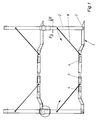
- zeigt zwei übereinander gestapelte Paletten in einer Seitenansicht;
- Fig. 2
- zeigt eine Draufsicht auf eine Palette, wobei die Stützen abgeklappt sind;
- Fig. 3
- zeigt die Verriegelung zweier aufeinanderstehender Stützen von zwei aufeinander gestapelten Paletten (Einzelheit X);
- Fig. 4
- zeigt die horizontale Verlängerung eines Überfahrsteges als Ausschnitt in einer Draufsicht;
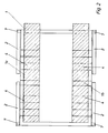
- Fig. 5
- zeigt einen Schnitt gemäß der Linie V-V in Fig. 1.
- Gemäß Fig. 1 besteht die Palette aus einem insgesamt mit 1 bezeichneten Bodenelement, sowie vier Stützen 2, die seitlich an dem Bodenelement, das aus den beiden Überfahrstegen 1a, 1b besteht, abklappbar angeordnet sind. Die das Bodenelement 1 bildenden beiden Überfahrstege 1a und 1b weisen eine trapezförmige Erhöhung 3 auf, die sich in etwa über die gesamte Länge eines Autodaches erstreckt. Durch diese Art der Ausbildung des Bodenelementes können entsprechend kürzerer Stützelemente zum Einsatz kommen, wodurch sich die gesamte Höhe einer derartigen Palette vermindern läßt, mit dem Ziel, daß bei zwei übereinander angeordneten Paletten die für einen LKW-Transporter maximale Höhe von 4,10 m nicht überschritten wird. Das Bodenelement weist im Bereich der trapezförmigen Erhöhung zwei Öffnungen 4 auf, die der Aufnahme der Gabel eines Gabelstaplers dienen.
- Um die Palette unterschiedlichen Achsabständen anpassen zu können, sind die Überfahrstege im Bereich der trapezförmigen Erhöhung horizontal verlängerbar ausgebildet. Hierzu sind die beiden Teile der Palette durch teleskopartig ineinander geführte Profile, beispielsweise Vierkantprofile 5 und 6 miteinander verbunden.
- Die Stützen 2 sind jeweils durch ein Gelenk 7 seitlich an dem Bodenelement 1 angeordnet. Die Arretierung der Stütze 2 in vertikaler Lage erfolgt durch eine Diagonalstrebe 8, die einerseits mit der Stütze 2 und andererseits mit dem Bodenelement 1 in Verbindung steht. Diese Diagonalstrebe 8 zum Zwecke des Abklappens ist lösbar, beispielsweise durch einen Bolzen 8a, mit der Stütze 2 verbunden.
- Jede Stütze 2 besteht aus zwei teleskopartig ineinander geführten Stützenelementen 2a und 2b. Hierbei ist das Stützenelement 2b in dem Stützenelement 2a geführt. Das Stützenelement 2a ist demzufolge in seinen Außenabmessungen größer ausgebildet, als das Stützenelement 2b. Die Fixierung der beiden teleskopartig ineinander geführten Stützenelemente 2a und 2b erfolgt durch einen Bolzen 14, der durch die in dem Stützenelement 2a angeordnete Bohrung 15 und die in dem Stützenelement 2b angeordnete Bohrung 16 hindurchragt.
- An seiner Oberseite weist das Stützenelement 2a eine Aussparung 9 zur Aufnahme des Stützenelementes 2b der Stütze der darüber gestapelten Palette auf. Diese Aussparung 9 besitzt einen Boden 9a zum Aufsetzen des Stützenelementes 2b der Stütze 2 der oberen Palette. Die Verriegelung des Stützenelementes 2b auf dem Stützenelement 2a erfolgt durch den Bolzen 13, der durch eine Bohrung 10 im Stützenelement 2a und die Bohrung 11 im Stützenelement 2b hindurchragt.
Claims (14)
- Vorrichtung zur Lagerung und zum Transport von Kraftfahrzeugen, insbesondere von Pkw
gekennzeichnet durch
eine das Fahrzeug aufnehmende Palette. - Vorrichtung nach Anspruch 1
dadurch gekennzeichnet, daß
ein überfahrbares Bodenelement (1) und am Bodenelement (1) angeordnete Stützen (2) zur stapelbaren Aufnahme einer weiteren Palette vorgesehen sind. - Vorrichtung nach Anspruch 2
dadurch gekennzeichnet, daß
das Bodenelement (1) mit einer trapezförmigen Erhöhung (3) versehen ist. - Vorrichtung nach Anspruch 3
dadurch gekennzeichnet, daß
sich die trapezförmige Erhöhung (3) etwa über die gesamte Länge eines Autodaches erstreckt. - Vorrichtung nach Anspruch 2
dadurch gekennzeichnet, daß
das Bodenelement (1) horizontal verlängerbar ausgebildet ist. - Vorrichtung nach Anspruch 2
dadurch gekennzeichnet, daß
das Bodenelement (1) zwei Öffnungen (4) zur Aufnahme der Gabel eines Gabelstaplers aufweist. - Vorrichtung nach Anspruch 2 bis 4
dadurch gekennzeichnet, daß
das Bodenelement (1) aus zwei Überfahrstegen (1a, 1b) besteht. - Vorrichtung nach Anspruch 2
dadurch gekennzeichnet, daß
die Stützen (2) abklappbar am Bodenelement (1) angeordnet sind. - Vorrichtung nach Anspruch 8
dadurch gekennzeichnet, daß
die Stützen (2) seitlich abklappbar am Bodenelement (1) angeordnet sind. - Vorrichtung nach Anspruch 2
dadurch gekennzeichnet, daß
die Stützen (2) in vertikaler Stellung arretierbar am Bodenelement (1) angeordnet sind. - Vorrichtung nach Anspruch 2
dadurch gekennzeichnet, daß
die Stützen (2) teleskopartig verlängerbar ausgebildet sind. - Vorrichtung nach Anspruch 11
dadurch gekennzeichnet, daß
eine Stütze (2) aus zwei Elementen (2a, 2b) besteht, wobei das eine Element (2a) der Aufnahme des Elementes (2b) der einen Stütze (2) und des Elementes (2b) der anderen Stütze (2) der darauf gestapelten Palette dient. - Vorrichtung nach Anspruch 2
dadurch gekennzeichnet, daß
im Stapelbetrieb die Stützen (2) zweier übereinander angeordneter Paletten miteinander verriegelbar sind. - Vorrichtung nach Anspruch 10
dadurch gekennzeichnet, daß
zur vertikalen Arretierung einer Stütze (2) eine Diagonalstrebe (8) vorgesehen ist, die lösbar an der Stütze und verschwenkbar mit dem Bodenelement verbunden ist.
Applications Claiming Priority (2)
| Application Number | Priority Date | Filing Date | Title |
|---|---|---|---|
| DE4023429 | 1990-07-24 | ||
| DE4023429A DE4023429C1 (de) | 1990-07-24 | 1990-07-24 |
Publications (2)
| Publication Number | Publication Date |
|---|---|
| EP0468349A1 EP0468349A1 (de) | 1992-01-29 |
| EP0468349B1 true EP0468349B1 (de) | 1994-04-20 |
Family
ID=6410878
Family Applications (1)
| Application Number | Title | Priority Date | Filing Date |
|---|---|---|---|
| EP91111911A Expired - Lifetime EP0468349B1 (de) | 1990-07-24 | 1991-07-17 | Vorrichtung zur Lagerung und zum Transport von Kraftfahrzeugen, insbesondere von Pkw |
Country Status (5)
| Country | Link |
|---|---|
| EP (1) | EP0468349B1 (de) |
| AT (1) | ATE104613T1 (de) |
| DE (1) | DE4023429C1 (de) |
| DK (1) | DK0468349T3 (de) |
| ES (1) | ES2051545T3 (de) |
Families Citing this family (5)
| Publication number | Priority date | Publication date | Assignee | Title |
|---|---|---|---|---|
| US5417332A (en) * | 1986-12-18 | 1995-05-23 | G & G Intellectual Properties, Inc. | Adjustable vehicle-carrying frame |
| US6119877A (en) * | 1986-12-18 | 2000-09-19 | G & G Intellectual Properties, Inc. | Adjustable vehicle-carrying frame |
| US5445278A (en) * | 1986-12-18 | 1995-08-29 | G & G Intellectual Properties, Inc. | Adjustable vehicle-carrying frame for insertion into differently-sized containers |
| US5769591A (en) * | 1993-02-04 | 1998-06-23 | Kar-Tainer International, Inc. | Frame structure and method of packing vehicle bodies |
| US5924248A (en) * | 1995-08-02 | 1999-07-20 | Kar-Tainer International Inc. | Collapsible frame device |
Family Cites Families (7)
| Publication number | Priority date | Publication date | Assignee | Title |
|---|---|---|---|---|
| DE1823261U (de) * | 1958-03-12 | 1960-12-08 | Clark Equipment Co | Transportvorrichtung fuer kraftfahrzeuge od. dgl. |
| US3003435A (en) * | 1958-11-14 | 1961-10-10 | Evans Prod Co | Automobile shipping device |
| DE1831979U (de) * | 1961-02-13 | 1961-05-25 | Heinrich Ufer Fa | Doppelter aufsatzrahmen aus winkeleisen, passend und zum aufsetzen auf flaschpaletten. |
| DE1973972U (de) * | 1967-09-16 | 1967-11-30 | Gmoehling Leichtmetall | Stapelpalette. |
| SE416389B (sv) * | 1979-02-05 | 1980-12-22 | Bilspedition Ab | Transportanordning |
| US4239275A (en) * | 1979-03-05 | 1980-12-16 | Jerr-Dan Corporation | Vehicle transporter |
| DE8804688U1 (de) * | 1988-04-11 | 1988-05-26 | Aspa-Foerdergeraete A. Schleifenbaum Gmbh & Co Kg, 5948 Schmallenberg, De |
-
1990
- 1990-07-24 DE DE4023429A patent/DE4023429C1/de not_active Expired - Lifetime
-
1991
- 1991-07-17 EP EP91111911A patent/EP0468349B1/de not_active Expired - Lifetime
- 1991-07-17 ES ES91111911T patent/ES2051545T3/es not_active Expired - Lifetime
- 1991-07-17 DK DK91111911.3T patent/DK0468349T3/da active
- 1991-07-17 AT AT9191111911T patent/ATE104613T1/de not_active IP Right Cessation
Also Published As
| Publication number | Publication date |
|---|---|
| DK0468349T3 (da) | 1994-05-16 |
| DE4023429C1 (de) | 1992-02-06 |
| ATE104613T1 (de) | 1994-05-15 |
| EP0468349A1 (de) | 1992-01-29 |
| ES2051545T3 (es) | 1994-06-16 |
Similar Documents
| Publication | Publication Date | Title |
|---|---|---|
| DE602004009361T2 (de) | Palette für luftfracht | |
| DE19849665B4 (de) | Frachtbehälter | |
| DE10134859A1 (de) | Mit Fallschirm abwerfbares Mehrzweckgeländerfahrzeug | |
| EP2441701B1 (de) | Transportvorrichtung und Transportmittel damit | |
| EP3604075B1 (de) | Hebbare tragvorrichtung | |
| WO2010146089A1 (de) | Transportsystem | |
| AT506371A1 (de) | Entladefahrzeug und kombination eines entladefahrzeuges mit einer behälterabdeckung | |
| EP0468349B1 (de) | Vorrichtung zur Lagerung und zum Transport von Kraftfahrzeugen, insbesondere von Pkw | |
| EP0893366B1 (de) | Vorrichtung zum Transport von Fahrzeugen, insbesondere Personenkraftwagen, Kleintransportern oder dergleichen | |
| DE69730326T2 (de) | Portalhubwagen | |
| DE19512246C2 (de) | Selbstfahrendes und auf ein Transportfahrzeug selbstauf- und selbstabladbares Verladesystem für Container oder Wechselbrücken | |
| DE60017160T2 (de) | Hubwagen | |
| EP0251219A2 (de) | Transportfahrzeug mit Selbstladeeinrichtung für Container, Raumzellen und Behälter | |
| DE2802267A1 (de) | Lastzug zum transport von fahrzeugen, insbesondere von mittleren und schweren industriefahrzeugen | |
| DE102005042243B4 (de) | Klappbarer Transportcontainer | |
| WO2020254073A1 (de) | Transportfahrzeug, verfahren zum aufnehmen einer last durch ein transportfahrzeug und system mit einem transportfahrzeug und einer last | |
| DE3108111A1 (de) | Lastfahrzeug-schwenkkran | |
| DE3842324A1 (de) | Strassentransportfahrzeug mit traggestellaufnahme fuer stehende tafeln, vorzugsweise glasscheiben und bordeigener abstuetzung | |
| DE202019101633U1 (de) | Transportmittel | |
| DE60114818T2 (de) | Containerträger | |
| EP0508404A1 (de) | Sicherungsvorrichtung für Transportgestelle | |
| EP0849115B1 (de) | Für ein Transportfahrzeug bestimmte Be- und Entladevorrichtung | |
| DE10043398A1 (de) | Verfahren zum Beladen von Fahrzeugen | |
| DE1531990A1 (de) | Container-Transport-,Umsetz- und Stapelgeraet | |
| DE20009296U1 (de) | Vorrichtung zum Verbringen und Mitführen von Hubwagen auf und von Fahrzeugen |
Legal Events
| Date | Code | Title | Description |
|---|---|---|---|
| PUAI | Public reference made under article 153(3) epc to a published international application that has entered the european phase |
Free format text: ORIGINAL CODE: 0009012 |
|
| AK | Designated contracting states |
Kind code of ref document: A1 Designated state(s): AT BE CH DK ES FR GB GR IT LI LU NL SE |
|
| 17P | Request for examination filed |
Effective date: 19911217 |
|
| 17Q | First examination report despatched |
Effective date: 19931008 |
|
| GRAA | (expected) grant |
Free format text: ORIGINAL CODE: 0009210 |
|
| AK | Designated contracting states |
Kind code of ref document: B1 Designated state(s): AT BE CH DK ES FR GB GR IT LI LU NL SE |
|
| REF | Corresponds to: |
Ref document number: 104613 Country of ref document: AT Date of ref document: 19940515 Kind code of ref document: T |
|
| REG | Reference to a national code |
Ref country code: DK Ref legal event code: T3 |
|
| REG | Reference to a national code |
Ref country code: ES Ref legal event code: FG2A Ref document number: 2051545 Country of ref document: ES Kind code of ref document: T3 |
|
| REG | Reference to a national code |
Ref country code: GR Ref legal event code: FG4A Free format text: 3011543 |
|
| ET | Fr: translation filed | ||
| ITF | It: translation for a ep patent filed |
Owner name: STUDIO JAUMANN |
|
| EPTA | Lu: last paid annual fee | ||
| GBT | Gb: translation of ep patent filed (gb section 77(6)(a)/1977) |
Effective date: 19940725 |
|
| EAL | Se: european patent in force in sweden |
Ref document number: 91111911.3 |
|
| PLBE | No opposition filed within time limit |
Free format text: ORIGINAL CODE: 0009261 |
|
| STAA | Information on the status of an ep patent application or granted ep patent |
Free format text: STATUS: NO OPPOSITION FILED WITHIN TIME LIMIT |
|
| 26N | No opposition filed | ||
| PGFP | Annual fee paid to national office [announced via postgrant information from national office to epo] |
Ref country code: LU Payment date: 19960701 Year of fee payment: 6 |
|
| PGFP | Annual fee paid to national office [announced via postgrant information from national office to epo] |
Ref country code: BE Payment date: 19960716 Year of fee payment: 6 |
|
| PGFP | Annual fee paid to national office [announced via postgrant information from national office to epo] |
Ref country code: SE Payment date: 19960718 Year of fee payment: 6 Ref country code: DK Payment date: 19960718 Year of fee payment: 6 |
|
| PGFP | Annual fee paid to national office [announced via postgrant information from national office to epo] |
Ref country code: CH Payment date: 19960722 Year of fee payment: 6 |
|
| PGFP | Annual fee paid to national office [announced via postgrant information from national office to epo] |
Ref country code: NL Payment date: 19960723 Year of fee payment: 6 |
|
| PGFP | Annual fee paid to national office [announced via postgrant information from national office to epo] |
Ref country code: GR Payment date: 19960731 Year of fee payment: 6 |
|
| PG25 | Lapsed in a contracting state [announced via postgrant information from national office to epo] |
Ref country code: LU Free format text: LAPSE BECAUSE OF NON-PAYMENT OF DUE FEES Effective date: 19970717 Ref country code: DK Free format text: LAPSE BECAUSE OF NON-PAYMENT OF DUE FEES Effective date: 19970717 |
|
| REG | Reference to a national code |
Ref country code: DK Ref legal event code: EBP |
|
| PG25 | Lapsed in a contracting state [announced via postgrant information from national office to epo] |
Ref country code: SE Effective date: 19970718 |
|
| PG25 | Lapsed in a contracting state [announced via postgrant information from national office to epo] |
Ref country code: LI Free format text: LAPSE BECAUSE OF NON-PAYMENT OF DUE FEES Effective date: 19970731 Ref country code: GR Free format text: LAPSE BECAUSE OF NON-PAYMENT OF DUE FEES Effective date: 19970731 Ref country code: CH Free format text: LAPSE BECAUSE OF NON-PAYMENT OF DUE FEES Effective date: 19970731 Ref country code: BE Free format text: LAPSE BECAUSE OF NON-PAYMENT OF DUE FEES Effective date: 19970731 |
|
| BERE | Be: lapsed |
Owner name: KIMM BRUNO Effective date: 19970731 |
|
| PG25 | Lapsed in a contracting state [announced via postgrant information from national office to epo] |
Ref country code: NL Free format text: LAPSE BECAUSE OF NON-PAYMENT OF DUE FEES Effective date: 19980201 |
|
| REG | Reference to a national code |
Ref country code: CH Ref legal event code: PL |
|
| NLV4 | Nl: lapsed or anulled due to non-payment of the annual fee |
Effective date: 19980201 |
|
| EUG | Se: european patent has lapsed |
Ref document number: 91111911.3 |
|
| PGFP | Annual fee paid to national office [announced via postgrant information from national office to epo] |
Ref country code: GB Payment date: 19990713 Year of fee payment: 9 |
|
| PGFP | Annual fee paid to national office [announced via postgrant information from national office to epo] |
Ref country code: FR Payment date: 19990715 Year of fee payment: 9 |
|
| PGFP | Annual fee paid to national office [announced via postgrant information from national office to epo] |
Ref country code: AT Payment date: 19990720 Year of fee payment: 9 |
|
| PGFP | Annual fee paid to national office [announced via postgrant information from national office to epo] |
Ref country code: ES Payment date: 19990728 Year of fee payment: 9 |
|
| PG25 | Lapsed in a contracting state [announced via postgrant information from national office to epo] |
Ref country code: GB Free format text: LAPSE BECAUSE OF NON-PAYMENT OF DUE FEES Effective date: 20000717 Ref country code: AT Free format text: LAPSE BECAUSE OF NON-PAYMENT OF DUE FEES Effective date: 20000717 |
|
| PG25 | Lapsed in a contracting state [announced via postgrant information from national office to epo] |
Ref country code: ES Free format text: LAPSE BECAUSE OF NON-PAYMENT OF DUE FEES Effective date: 20000718 |
|
| GBPC | Gb: european patent ceased through non-payment of renewal fee |
Effective date: 20000717 |
|
| PG25 | Lapsed in a contracting state [announced via postgrant information from national office to epo] |
Ref country code: FR Free format text: LAPSE BECAUSE OF NON-PAYMENT OF DUE FEES Effective date: 20010330 |
|
| REG | Reference to a national code |
Ref country code: FR Ref legal event code: ST |
|
| REG | Reference to a national code |
Ref country code: ES Ref legal event code: FD2A Effective date: 20010810 |
|
| PG25 | Lapsed in a contracting state [announced via postgrant information from national office to epo] |
Ref country code: IT Free format text: LAPSE BECAUSE OF NON-PAYMENT OF DUE FEES;WARNING: LAPSES OF ITALIAN PATENTS WITH EFFECTIVE DATE BEFORE 2007 MAY HAVE OCCURRED AT ANY TIME BEFORE 2007. THE CORRECT EFFECTIVE DATE MAY BE DIFFERENT FROM THE ONE RECORDED. Effective date: 20050717 |