EP0468328A1 - Miroir pour changer la forme géométrique d'un faisceau lumineux - Google Patents
Miroir pour changer la forme géométrique d'un faisceau lumineux Download PDFInfo
- Publication number
- EP0468328A1 EP0468328A1 EP91111740A EP91111740A EP0468328A1 EP 0468328 A1 EP0468328 A1 EP 0468328A1 EP 91111740 A EP91111740 A EP 91111740A EP 91111740 A EP91111740 A EP 91111740A EP 0468328 A1 EP0468328 A1 EP 0468328A1
- Authority
- EP
- European Patent Office
- Prior art keywords
- segments
- mirror
- mirror according
- light beam
- offset
- Prior art date
- Legal status (The legal status is an assumption and is not a legal conclusion. Google has not performed a legal analysis and makes no representation as to the accuracy of the status listed.)
- Granted
Links
Images


Classifications
-
- G—PHYSICS
- G02—OPTICS
- G02B—OPTICAL ELEMENTS, SYSTEMS OR APPARATUS
- G02B27/00—Optical systems or apparatus not provided for by any of the groups G02B1/00 - G02B26/00, G02B30/00
- G02B27/09—Beam shaping, e.g. changing the cross-sectional area, not otherwise provided for
- G02B27/0938—Using specific optical elements
- G02B27/0977—Reflective elements
- G02B27/0983—Reflective elements being curved
-
- B—PERFORMING OPERATIONS; TRANSPORTING
- B23—MACHINE TOOLS; METAL-WORKING NOT OTHERWISE PROVIDED FOR
- B23K—SOLDERING OR UNSOLDERING; WELDING; CLADDING OR PLATING BY SOLDERING OR WELDING; CUTTING BY APPLYING HEAT LOCALLY, e.g. FLAME CUTTING; WORKING BY LASER BEAM
- B23K26/00—Working by laser beam, e.g. welding, cutting or boring
- B23K26/02—Positioning or observing the workpiece, e.g. with respect to the point of impact; Aligning, aiming or focusing the laser beam
- B23K26/06—Shaping the laser beam, e.g. by masks or multi-focusing
- B23K26/073—Shaping the laser spot
- B23K26/0738—Shaping the laser spot into a linear shape
-
- G—PHYSICS
- G02—OPTICS
- G02B—OPTICAL ELEMENTS, SYSTEMS OR APPARATUS
- G02B27/00—Optical systems or apparatus not provided for by any of the groups G02B1/00 - G02B26/00, G02B30/00
- G02B27/09—Beam shaping, e.g. changing the cross-sectional area, not otherwise provided for
-
- G—PHYSICS
- G02—OPTICS
- G02B—OPTICAL ELEMENTS, SYSTEMS OR APPARATUS
- G02B27/00—Optical systems or apparatus not provided for by any of the groups G02B1/00 - G02B26/00, G02B30/00
- G02B27/09—Beam shaping, e.g. changing the cross-sectional area, not otherwise provided for
- G02B27/0911—Anamorphotic systems
-
- G—PHYSICS
- G02—OPTICS
- G02B—OPTICAL ELEMENTS, SYSTEMS OR APPARATUS
- G02B5/00—Optical elements other than lenses
- G02B5/08—Mirrors
-
- G—PHYSICS
- G02—OPTICS
- G02B—OPTICAL ELEMENTS, SYSTEMS OR APPARATUS
- G02B5/00—Optical elements other than lenses
- G02B5/08—Mirrors
- G02B5/10—Mirrors with curved faces
Definitions
- the invention relates to a mirror for changing the geometric shape of a light beam and a method for using the mirror.
- Mirrors for changing the geometric shape of a light beam are widely used. It is difficult to generate a radiation cross section which has an essentially linear to rectangular cross section, within which the intensity has a predetermined course, in particular is constant in the longitudinal direction. Such radiation cross sections are required in particular for surface treatment with lasers, to name just one essential area of application.
- the shaping optics ensure that the laser beam has an essentially rectangular to linear cross section when it strikes the workpiece, within which the intensity has an almost constant value. If a beam with such a cross-section is guided over the workpiece surface at a constant speed and parallel to an edge pair of the rectangle, then the energy profile within the irradiated strip is uniform.
- JP 63-77178 A describes a facet mirror made up of a multiplicity of plane mirrors which are arranged in a mosaic-like manner tangentially against a paraboloid surface and which concentrate a laser beam on a rectangle with essentially the extent of a single plane mirror. A line profile cannot be reached because the individual mirrors have no focusing effect. The manufacture of such an arrangement is complicated.
- Faceted mirrors are also from Ream, S. L, "A Convex Beam Integrator", Laser Focus, Nov. 1979, pp. 68-71, US 4,518,232 and JP 59-151 101 A, the latter with spherical facets, are known.
- the object of the invention is to give a light beam with any beam cross section a linear to rectangular beam cross section with a certain intensity distribution with only one optical image, the effects of the interference occurring at longer wavelengths being kept as low as possible.
- the exact manufacture should be facilitated by the suitability for inherently precise manufacturing methods.
- the mirror is made up of a plurality of segments of rotating bodies lined up, the axes of rotation of which at least approximately overlap in a linear to rectangular area of an object, the size of which is selected such that the light beam to be reshaped at the same time falls on several of the segments and all segments are shaped and aligned such that a zone of the light beam is reflected exactly once by a segment and is directed at a section of the linear to rectangular area of the object, in which the axes of rotation overlap and open approximately All zones of the light bundle are at least approximately superimposed on this section, the individual segments being offset from one another in steps.
- the mirror surfaces are surfaces of revolution that are inherently more precisely manufactured than plane surfaces.
- this mirror is that the light beam is broken down into several strip-shaped areas, which are superimposed and directed onto a line, with only a single reflection of each light beam area being performed for this purpose.
- This optical transformation of the beam geometry can provide an excellent homogeneity of the intensity distribution, which can be influenced by the number of mirror segments, with minimal energy losses in the optical imaging.
- mirrors according to the invention correspond in structure to those specified in DE 39 12 237 A.
- the step-like offset of the segments changes the coherence conditions for the light contributions from the individual segments to such an extent that interference effects are suppressed.
- the axial step-shaped offset according to claim 2 means that the rays reflected from adjacent segments towards the line focus enclose a larger angle with one another. As a result, axial interference structures that arise in the line focus are structured more finely and are therefore less disruptive for the mentioned use cases.
- Claim 10 relates to a method for surface treatment with laser and mirror according to one of claims 1 to 9.
- FIG. 1 shows a mirror (21) which images an incident light bundle (27) on a linear region (28) of an object (29).
- the linear region (28) lies on the common axis of rotation (20) of the conical mirror segments (22, 23, 24).
- the segments (22, 23, 24) are selected according to the number, size, center distance and opening angle of the cone so that each segment (22, 23, 24) is a zone of the incident light beam (27) by one-time reflection on the same linear for all Area (28) maps as a line focus and that the entire incident light beam (27) is detected.
- the intermediate pieces (23a, 24a) arranged between the mirror segments (22, 23, 24) are designed in such a way that they include a small area (25) of the respectively following segment (22, 23) through the edges (23a ', 24a ') of the respectively preceding segment (23, 24) are shadowed by the incident light beam (27).
- the mirror can be assembled from the individual segments (22, 23, 24) and intermediate rings (23a, 24a).
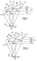
- the reflecting segments (32, 33, 34) and (42, 43, 44) are curved, specifically convex in FIG. 2 and concave in FIG. 3. Otherwise, the mirrors (31, 41) are constructed in the same way as the mirror (21) according to FIG. 1 and the same reference numerals designate the same parts.
- mirrors (31, 41) with curved mirrored segments (32, 33, 34; 42, 43, 44) (FIGS. 2, 3) is that the number (and thus the length) of the segments (32 , 33, 34; 42, 43, 44) on the one hand and the length of the linear region (28) on the other hand independently of can choose each other.
- the segments (32, 33, 34; 42, 43, 44) in FIGS. 2, 3 preferably have a circular, parabolic or elliptical cross section in the direction of the axis of rotation, so that Toroidal, spherical, paraboloid or ellipsoid surfaces are created as reflecting segments (32, 33, 34; 42, 43, 44).
- Different shapes can also be appropriate for special intensity distributions in the direction of the axes of rotation.
- the angle of incidence of the laser beam (27) and its geometric properties can vary within a wide range.
- FIG. 4 shows the use of a mirror (51) for irradiating the surface of a workpiece (59) in a linear work area (58) on the axis of rotation (50) of the mirror (51).
- the light bundle (57) is neither parallel nor axially parallel to the axis of rotation (50) but divergent with a source point (60) on the axis of rotation (50), so it is by the five segments (52-56) of the mirror (51) on the linear Work area (58) is shown, wherein at the rear edges (52a'-56a ') of the segments (52-56) there is a jump in the image from the end of the work area (58) at the beginning.
- the working area (58) is an interval on the axis of rotation (50).
- the inclinations and lengths of the conical segments (52-56) are chosen so that the associated focal lines on the axis of rotation (50) are of the same length and have the same position.
- the suitable dimensions can be easily calculated using known numerical calculation methods.
- the mirror (51) like the mirrors (21, 31, 41) described in FIGS. 1-3, has a step-like structure, shading between the different mirror segments (52-56) by the front mirror segments (52-55) Intermediate pieces (52a-55a) are located.
- part of the rear segments (53-56) shown here by way of example on part (61) on segment (56), is shadowed by the front segments (52-55).
- the light beam (57) emanating from the source point (60) does not fall onto the mirror (51) in an axis-parallel manner, the advantages described above for FIGS. 1-3 are also present here.
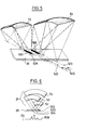
- FIGS. 5 and 6 illustrate a variant of the mirror (21) according to the invention, in which the segments (52, 53, 54) with their axes of rotation (522, 523, 524) are offset from one another step by step in parallel.
- 5 shows a perspective view
- FIG. 6 shows a front view together with a resulting intensity profile (500).
- Segments (52, 53, 54) of rotating bodies are now offset with their axes of rotation (522, 523, 524) laterally parallel to a central axis (520).
- the line foci (582, 583) of the individual segments (52, 53) lie on the respective axes of rotation (522, 523) in a rectangular area (528) on the object (29).
- An offset of 0.1 mm to 0.3 mm is typical.
- An offset by approximately the width of the individual line focus of the segments (52, 53, 54) is sufficient to suppress interference.
- a rectangular area with a targeted intensity profile can be illuminated. This is done by giving the adjacent individual lines different intensities.
- the intensities can be varied over the segment width or simply by taking advantage of the fact that the segments (52, 53, 54) are illuminated differently depending on the profile of the light beam (27).
- the offset for each segment (52, 53, 54) can be selected independently, as shown in FIG. 6.
- the segments (52, 53, 54) are drawn in with the same sector angles for clarification.
- the size of the sectors (52, 53, 54) should be selected so that the light beam (27) is fully covered and no gaps are created.
- offset is e.g. the vertical offset, which causes the contributions of the individual segments to be defocused, and the offset with tilting of the axes of rotation.
Landscapes
- Physics & Mathematics (AREA)
- Optics & Photonics (AREA)
- General Physics & Mathematics (AREA)
- Engineering & Computer Science (AREA)
- Plasma & Fusion (AREA)
- Mechanical Engineering (AREA)
- Optical Elements Other Than Lenses (AREA)
- Laser Beam Processing (AREA)
- Lenses (AREA)
- Chemical Vapour Deposition (AREA)
Applications Claiming Priority (2)
| Application Number | Priority Date | Filing Date | Title |
|---|---|---|---|
| DE4023904A DE4023904A1 (de) | 1990-07-27 | 1990-07-27 | Spiegel zur veraenderung der geometrischen gestalt eines lichtbuendels |
| DE4023904 | 1990-07-27 |
Publications (2)
| Publication Number | Publication Date |
|---|---|
| EP0468328A1 true EP0468328A1 (fr) | 1992-01-29 |
| EP0468328B1 EP0468328B1 (fr) | 1996-03-20 |
Family
ID=6411148
Family Applications (1)
| Application Number | Title | Priority Date | Filing Date |
|---|---|---|---|
| EP91111740A Expired - Lifetime EP0468328B1 (fr) | 1990-07-27 | 1991-07-15 | Miroir pour changer la forme géométrique d'un faisceau lumineux |
Country Status (4)
| Country | Link |
|---|---|
| US (1) | US5148326A (fr) |
| EP (1) | EP0468328B1 (fr) |
| JP (1) | JPH04251802A (fr) |
| DE (2) | DE4023904A1 (fr) |
Cited By (7)
| Publication number | Priority date | Publication date | Assignee | Title |
|---|---|---|---|---|
| EP0630720A1 (fr) * | 1993-06-25 | 1994-12-28 | Honda Giken Kogyo Kabushiki Kaisha | Système optique pour générateur de faisceau laser |
| US5690845A (en) * | 1994-10-07 | 1997-11-25 | Sumitomo Electric Industries, Ltd. | Optical device for laser machining |
| WO1998008128A1 (fr) * | 1996-08-16 | 1998-02-26 | Fraunhofer-Gesellschaft zur Förderung der angewandten Forschung e.V. | Dispositif pour la transformation geometrique d'un champ de rayonnement |
| WO2007093436A1 (fr) * | 2006-02-17 | 2007-08-23 | Carl Zeiss Smt Ag | Intégrateur optique pour un système d'éclairage d'un appareil d'exposition de projection microlithographique |
| WO2007098777A1 (fr) * | 2006-02-24 | 2007-09-07 | Trumpf Werkzeugmaschinen Gmbh +Co. Kg | Ensemble miroirs pour installation de traitement au laser, doté d'un miroir comportant au moins deux zones réfléchissantes et une zone d'ombre |
| US8395756B2 (en) | 2006-02-17 | 2013-03-12 | Carl Zeiss Smt Gmbh | Illumination system for a microlithographic projection exposure apparatus |
| CN109759799A (zh) * | 2019-03-12 | 2019-05-17 | 西北核技术研究所 | 一种旋转半椭球非回转反射面结构的加工方法 |
Families Citing this family (21)
| Publication number | Priority date | Publication date | Assignee | Title |
|---|---|---|---|---|
| US5285320A (en) * | 1989-04-14 | 1994-02-08 | Carl-Zeiss-Stiftung | Mirror for changing the geometrical form of a light beam |
| JP2829192B2 (ja) * | 1992-05-15 | 1998-11-25 | 住友電気工業株式会社 | レ−ザビ−ムスキャナ |
| JP2655465B2 (ja) * | 1993-01-20 | 1997-09-17 | 日本電気株式会社 | 反射型ホモジナイザーおよび反射型照明光学装置 |
| DE4314601C2 (de) * | 1993-05-04 | 1996-08-08 | Fraunhofer Ges Forschung | Vorrichtung und Verfahren zum mit fokussiertem Licht erfolgenden Behandeln von kornorientierten Werkstücken |
| US5397327A (en) * | 1993-07-27 | 1995-03-14 | Coherent, Inc. | Surgical laser handpiece for slit incisions |
| DE19514626C2 (de) * | 1995-04-26 | 1997-03-06 | Fraunhofer Ges Forschung | Anordnung zur Formung des geometrischen Querschnitts eines Strahlungsfeldes eines oder mehrerer Festkörper- und/oder Halbleiterlaser(s) |
| DE19514624C2 (de) * | 1995-04-26 | 1997-03-27 | Fraunhofer Ges Forschung | Anordnung zur Formung des geometrischen Querschnitts eines Strahlungsfeldes eines oder mehrerer Gaslaser(s) |
| DE19514625C2 (de) * | 1995-04-26 | 1997-03-06 | Fraunhofer Ges Forschung | Anordnung zur Formung des geometrischen Querschnitts eines Strahlungsfelds eines oder mehrerer Festkörper- und/oder Halbleiterlaser(s) |
| GB2313206A (en) * | 1996-05-17 | 1997-11-19 | Crowcon Detection Instr Limite | Optical component for distributing radiation to foci |
| FR2753522B1 (fr) * | 1996-09-19 | 1998-12-04 | Valeo Vision | Feu de signalisation de vehicule automobile, comportant un miroir a paves deviateurs perfectionnes |
| DE19805726A1 (de) * | 1998-02-12 | 1999-09-02 | Fraunhofer Ges Forschung | Verfahren und Vorrichtung zur Erhöhung der Prozeßstabilität bei der Lasermaterialbearbeitung |
| US6075912A (en) * | 1998-03-17 | 2000-06-13 | Polaroid Corporation | Apparatus for coupling radiation beams into an optical waveguide |
| US6324320B1 (en) | 1998-03-17 | 2001-11-27 | Polaroid Corporation | Optical apparatus for producing a high-brightness multi-laser radiation source |
| JP2001244213A (ja) * | 1999-12-24 | 2001-09-07 | Semiconductor Energy Lab Co Ltd | レーザ照射装置並びに半導体装置の作製方法 |
| US6856630B2 (en) * | 2000-02-02 | 2005-02-15 | Semiconductor Energy Laboratory Co., Ltd. | Beam homogenizer, laser irradiation apparatus, semiconductor device, and method of fabricating the semiconductor device |
| PT102735A (pt) * | 2002-03-05 | 2003-09-30 | Ibe Ind De Bens De Equipamento | Processo e maquina de corte e/ou soldadura e/ou gravacao de corpos |
| EP1642173A1 (fr) * | 2003-07-09 | 2006-04-05 | Carl Zeiss SMT AG | Miroirs a facettes et procede de production de facettes de miroir |
| DE10345430A1 (de) * | 2003-09-30 | 2005-06-02 | Carl Zeiss Sms Gmbh | Beleuchtungsvorrichtung |
| JP5234462B2 (ja) * | 2009-01-21 | 2013-07-10 | 国立大学法人 東京大学 | 光学素子、及び赤外線センサ |
| US20110063205A1 (en) * | 2009-09-15 | 2011-03-17 | Motorola, Inc. | Display magnifier |
| DE102017100945B4 (de) | 2017-01-18 | 2019-06-27 | LIMO GmbH | Linsenvorrichtung oder Spiegelvorrichtung sowie Vorrichtung zur Homogenisierung von Licht |
Citations (3)
| Publication number | Priority date | Publication date | Assignee | Title |
|---|---|---|---|---|
| FR2525733A1 (fr) * | 1982-04-23 | 1983-10-28 | Auteroche Sa | Reflecteur a paraboloides multiples |
| US4518232A (en) * | 1983-08-24 | 1985-05-21 | Avco Everett Research Laboratory, Inc. | Method and apparatus for optical beam shaping |
| EP0395910A2 (fr) * | 1989-04-29 | 1990-11-07 | Firma Carl Zeiss | Miroir pour la modification de la configuration géométrique d'un faisceau de lumière |
Family Cites Families (18)
| Publication number | Priority date | Publication date | Assignee | Title |
|---|---|---|---|---|
| US1919561A (en) * | 1929-04-29 | 1933-07-25 | Kogel Gustav | Concave mirror |
| CH160209A (de) * | 1930-09-23 | 1933-02-28 | Koegel Gustav Prof Ing Dr | Hohlspiegel zur Erzeugung von plastischen Bildern. |
| US3613659A (en) * | 1968-10-14 | 1971-10-19 | Robert M Phillips | Solar-energy-concentrating device |
| US3523721A (en) * | 1968-12-09 | 1970-08-11 | Zeiss Jena Veb Carl | Spherically corrected fresnel lenses and mirrors with partial field correction |
| US3888589A (en) * | 1974-02-11 | 1975-06-10 | Pilkington Perkin Elmer Ltd | Reflection grating optical odometer |
| US4110009A (en) * | 1975-12-19 | 1978-08-29 | Bunch Jesse C | Heliostat apparatus |
| US4195913A (en) * | 1977-11-09 | 1980-04-01 | Spawr Optical Research, Inc. | Optical integration with screw supports |
| DE2808359C3 (de) * | 1978-02-27 | 1980-09-04 | Erwin Sick Gmbh Optik-Elektronik, 7808 Waldkirch | Suchgerät für Löcher in Bahnen |
| US4327972A (en) * | 1979-10-22 | 1982-05-04 | Coulter Electronics, Inc. | Redirecting surface for desired intensity profile |
| US4484334A (en) * | 1981-11-17 | 1984-11-20 | Allied Corporation | Optical beam concentrator |
| US4475027A (en) * | 1981-11-17 | 1984-10-02 | Allied Corporation | Optical beam homogenizer |
| JPS59151101A (ja) * | 1983-02-08 | 1984-08-29 | Toshiba Corp | 凹面鏡 |
| GB8306951D0 (en) * | 1983-03-14 | 1983-04-20 | Ici Plc | Energy beam focusing apparatus |
| SU1171744A1 (ru) * | 1984-02-07 | 1985-08-07 | Предприятие П/Я Г-4671 | Диспергирующее устройство |
| US4620230A (en) * | 1984-09-24 | 1986-10-28 | The Boeing Company | Display system |
| JPS6237350A (ja) * | 1985-08-12 | 1987-02-18 | Toshiba Corp | 表面熱処理装置 |
| JPS6377178A (ja) * | 1986-09-19 | 1988-04-07 | Fanuc Ltd | レ−ザ用集光鏡 |
| US4798446A (en) * | 1987-09-14 | 1989-01-17 | The United States Of America As Represented By The United States Department Of Energy | Aplanatic and quasi-aplanatic diffraction gratings |
-
1990
- 1990-07-27 DE DE4023904A patent/DE4023904A1/de not_active Withdrawn
-
1991
- 1991-07-15 EP EP91111740A patent/EP0468328B1/fr not_active Expired - Lifetime
- 1991-07-15 DE DE59107565T patent/DE59107565D1/de not_active Expired - Fee Related
- 1991-07-29 US US07/737,448 patent/US5148326A/en not_active Expired - Lifetime
- 1991-07-29 JP JP3210455A patent/JPH04251802A/ja active Pending
Patent Citations (3)
| Publication number | Priority date | Publication date | Assignee | Title |
|---|---|---|---|---|
| FR2525733A1 (fr) * | 1982-04-23 | 1983-10-28 | Auteroche Sa | Reflecteur a paraboloides multiples |
| US4518232A (en) * | 1983-08-24 | 1985-05-21 | Avco Everett Research Laboratory, Inc. | Method and apparatus for optical beam shaping |
| EP0395910A2 (fr) * | 1989-04-29 | 1990-11-07 | Firma Carl Zeiss | Miroir pour la modification de la configuration géométrique d'un faisceau de lumière |
Non-Patent Citations (4)
| Title |
|---|
| APPLIED OPTICS Band 19, Nr. 20, 1980, Seiten 3554-3561, New York, US; B. AUTHIER et al.: "High concentration solar collector of the stepped spherical type: optical design characteristics" * |
| NAVY TECHNICAL DISCLOSURE BULLETIN Band 10, Nr. 4, 1985, Seiten 25-32, Arlington, Virginia, US; B.H. RIPIN: "Induced spatial incoherence optical delay element" * |
| OPTICAL ENGINEERING Band 27, Nr. 11, 1988, Seiten 999-1007; Bellingham, WA, US; F.M. DICKEY et al.: "Multifaceted laser beam integrators: general formulation and design concepts" * |
| PATENT ABSTRACTS OF JAPAN Band 8, Nr. 286 (P-324), 27. Dezember 1984; & JP - A - 59151101 (TOSHIBA) 29.08.1984 (Kat. D) * |
Cited By (13)
| Publication number | Priority date | Publication date | Assignee | Title |
|---|---|---|---|---|
| EP0630720A1 (fr) * | 1993-06-25 | 1994-12-28 | Honda Giken Kogyo Kabushiki Kaisha | Système optique pour générateur de faisceau laser |
| US5690845A (en) * | 1994-10-07 | 1997-11-25 | Sumitomo Electric Industries, Ltd. | Optical device for laser machining |
| WO1998008128A1 (fr) * | 1996-08-16 | 1998-02-26 | Fraunhofer-Gesellschaft zur Förderung der angewandten Forschung e.V. | Dispositif pour la transformation geometrique d'un champ de rayonnement |
| US8520307B2 (en) | 2006-02-17 | 2013-08-27 | Carl Zeiss Smt Gmbh | Optical integrator for an illumination system of a microlithographic projection exposure apparatus |
| US7880969B2 (en) | 2006-02-17 | 2011-02-01 | Carl Zeiss Smt Ag | Optical integrator for an illumination system of a microlithographic projection exposure apparatus |
| US8395756B2 (en) | 2006-02-17 | 2013-03-12 | Carl Zeiss Smt Gmbh | Illumination system for a microlithographic projection exposure apparatus |
| WO2007093436A1 (fr) * | 2006-02-17 | 2007-08-23 | Carl Zeiss Smt Ag | Intégrateur optique pour un système d'éclairage d'un appareil d'exposition de projection microlithographique |
| US9217930B2 (en) | 2006-02-17 | 2015-12-22 | Carl Zeiss Smt Gmbh | Illumination system for a microlithographic projection exposure apparatus |
| US9575414B2 (en) | 2006-02-17 | 2017-02-21 | Carl Zeiss Smt Gmbh | Illumination system for a microlithographic projection exposure apparatus |
| WO2007098777A1 (fr) * | 2006-02-24 | 2007-09-07 | Trumpf Werkzeugmaschinen Gmbh +Co. Kg | Ensemble miroirs pour installation de traitement au laser, doté d'un miroir comportant au moins deux zones réfléchissantes et une zone d'ombre |
| CN101394966B (zh) * | 2006-02-24 | 2011-10-26 | 通快机床两合公司 | 具有一具有至少两个镜区域和一个阴影区的反射镜的激光加工设备反射镜组件 |
| US8246185B2 (en) | 2006-02-24 | 2012-08-21 | Trumpf Werkzeugmaschinen Gmbh +Co. Kg | Mirror arrangement of a laser processing system |
| CN109759799A (zh) * | 2019-03-12 | 2019-05-17 | 西北核技术研究所 | 一种旋转半椭球非回转反射面结构的加工方法 |
Also Published As
| Publication number | Publication date |
|---|---|
| JPH04251802A (ja) | 1992-09-08 |
| US5148326A (en) | 1992-09-15 |
| DE4023904A1 (de) | 1992-01-30 |
| EP0468328B1 (fr) | 1996-03-20 |
| DE59107565D1 (de) | 1996-04-25 |
Similar Documents
| Publication | Publication Date | Title |
|---|---|---|
| EP0468328A1 (fr) | Miroir pour changer la forme géométrique d'un faisceau lumineux | |
| DE2908195C2 (de) | Vorrichtung zum Bearbeiten eines Werkstücks mit einem Laserstrahl | |
| DE3734656C2 (de) | Verfahren und Vorrichtung zur Herstellung von Linsen oder ähnlich gestalteten Gegenständen mittels Laserstrahlung | |
| DE2431265C2 (de) | Optische Einrichtung zur Erzeugung eines sehr kleinen Strahls | |
| DE112016002870T5 (de) | Optische Elementanordnungen zum Verändern des Strahlparameterprodukts in Laserabgabesystemen | |
| DE4328894C2 (de) | Laserbearbeitungsvorrichtung und zugehöriges Verfahren | |
| DE3911443C2 (de) | Optische Leuchtenabdeckung mit Fresnel-Prismen, deren Verwendung sowie ein Verfahren zu ihrer Herstellung | |
| EP0835715A1 (fr) | Dispositif et procédé de traitement d'une pièce avec un laser à diode | |
| EP0395910B1 (fr) | Miroir pour la modification de la configuration géométrique d'un faisceau de lumière | |
| EP2429755B1 (fr) | Dispositif et procédé permettant l'usinage périphérique au laser d'un cordon de matière | |
| EP3752314A1 (fr) | Procédé et dispositif pour insérer une ligne de séparation dans un matériau transparent cassant, ainsi qu'élément pourvu d'une ligne de séparation, pouvant être fabriqué selon le procédé | |
| DE3418188C2 (fr) | ||
| DE2927406A1 (de) | Geraet zum ziehen von beugungsgitterlinien | |
| WO2003016963A2 (fr) | Systeme et dispositif d'homogeneisation de faisceau optique | |
| DE19752416A1 (de) | Verfahren und Vorrichtung zum Kombinieren der Strahlungsleistung einer linearen Anordnung von Strahlenquellen | |
| DE3912237A1 (de) | Spiegel zur veraenderung der geometrischen gestalt eines lichtbuendels | |
| DE19846368C1 (de) | Vorrichtung zum Schneiden, Schweißen, Bohren oder Abtragen eines Werkstückes mittels eines Laserstrahles | |
| DE102019108681A1 (de) | Vorrichtung und Verfahren zur Erzeugung eines Doppel- oder Vielfachspots in der Lasermaterialbearbeitung | |
| EP2675609B1 (fr) | Procédé de fusion laser sélective et système permettant de mettre en uvre un tel procédé | |
| DE4219809A1 (de) | Verfahren und Vorrichtung zum Abtragen einer Oberfläche | |
| DE6806092U (de) | Optisches system zum fokussieren eines von einem impuls-laser ausgesandten buendels monochrotischer lichtstrahlen | |
| DE112017006002T5 (de) | Laserstrahlbearbeitungsverfahren und Laserstrahlmaschine | |
| DE102015113141A1 (de) | Verfahren zur Bearbeitung einer Werkstückoberfläche und Werkstück | |
| DE4018355C2 (fr) | ||
| DE3530929C2 (de) | Einrichtung zur Transmission von Strahlungsenergie |
Legal Events
| Date | Code | Title | Description |
|---|---|---|---|
| PUAI | Public reference made under article 153(3) epc to a published international application that has entered the european phase |
Free format text: ORIGINAL CODE: 0009012 |
|
| AK | Designated contracting states |
Kind code of ref document: A1 Designated state(s): DE FR GB SE |
|
| 17P | Request for examination filed |
Effective date: 19920706 |
|
| 17Q | First examination report despatched |
Effective date: 19940803 |
|
| GRAH | Despatch of communication of intention to grant a patent |
Free format text: ORIGINAL CODE: EPIDOS IGRA |
|
| GRAA | (expected) grant |
Free format text: ORIGINAL CODE: 0009210 |
|
| AK | Designated contracting states |
Kind code of ref document: B1 Designated state(s): DE FR GB SE |
|
| ET | Fr: translation filed | ||
| REF | Corresponds to: |
Ref document number: 59107565 Country of ref document: DE Date of ref document: 19960425 |
|
| PGFP | Annual fee paid to national office [announced via postgrant information from national office to epo] |
Ref country code: GB Payment date: 19960613 Year of fee payment: 6 |
|
| PGFP | Annual fee paid to national office [announced via postgrant information from national office to epo] |
Ref country code: FR Payment date: 19960617 Year of fee payment: 6 |
|
| GBT | Gb: translation of ep patent filed (gb section 77(6)(a)/1977) |
Effective date: 19960522 |
|
| PGFP | Annual fee paid to national office [announced via postgrant information from national office to epo] |
Ref country code: SE Payment date: 19960619 Year of fee payment: 6 |
|
| PLBE | No opposition filed within time limit |
Free format text: ORIGINAL CODE: 0009261 |
|
| STAA | Information on the status of an ep patent application or granted ep patent |
Free format text: STATUS: NO OPPOSITION FILED WITHIN TIME LIMIT |
|
| 26N | No opposition filed | ||
| PG25 | Lapsed in a contracting state [announced via postgrant information from national office to epo] |
Ref country code: GB Free format text: LAPSE BECAUSE OF NON-PAYMENT OF DUE FEES Effective date: 19970715 |
|
| PG25 | Lapsed in a contracting state [announced via postgrant information from national office to epo] |
Ref country code: SE Effective date: 19970716 |
|
| GBPC | Gb: european patent ceased through non-payment of renewal fee |
Effective date: 19970715 |
|
| PG25 | Lapsed in a contracting state [announced via postgrant information from national office to epo] |
Ref country code: FR Free format text: LAPSE BECAUSE OF NON-PAYMENT OF DUE FEES Effective date: 19980331 |
|
| EUG | Se: european patent has lapsed |
Ref document number: 91111740.6 |
|
| REG | Reference to a national code |
Ref country code: FR Ref legal event code: ST |
|
| PGFP | Annual fee paid to national office [announced via postgrant information from national office to epo] |
Ref country code: DE Payment date: 20080722 Year of fee payment: 18 |
|
| PG25 | Lapsed in a contracting state [announced via postgrant information from national office to epo] |
Ref country code: DE Free format text: LAPSE BECAUSE OF NON-PAYMENT OF DUE FEES Effective date: 20100202 |