EP0468328A1 - Mirror for altering the geometric shape of a light beam - Google Patents
Mirror for altering the geometric shape of a light beam Download PDFInfo
- Publication number
- EP0468328A1 EP0468328A1 EP91111740A EP91111740A EP0468328A1 EP 0468328 A1 EP0468328 A1 EP 0468328A1 EP 91111740 A EP91111740 A EP 91111740A EP 91111740 A EP91111740 A EP 91111740A EP 0468328 A1 EP0468328 A1 EP 0468328A1
- Authority
- EP
- European Patent Office
- Prior art keywords
- segments
- mirror
- mirror according
- light beam
- offset
- Prior art date
- Legal status (The legal status is an assumption and is not a legal conclusion. Google has not performed a legal analysis and makes no representation as to the accuracy of the status listed.)
- Granted
Links
Images


Classifications
-
- G—PHYSICS
- G02—OPTICS
- G02B—OPTICAL ELEMENTS, SYSTEMS OR APPARATUS
- G02B27/00—Optical systems or apparatus not provided for by any of the groups G02B1/00 - G02B26/00, G02B30/00
- G02B27/09—Beam shaping, e.g. changing the cross-sectional area, not otherwise provided for
- G02B27/0938—Using specific optical elements
- G02B27/0977—Reflective elements
- G02B27/0983—Reflective elements being curved
-
- B—PERFORMING OPERATIONS; TRANSPORTING
- B23—MACHINE TOOLS; METAL-WORKING NOT OTHERWISE PROVIDED FOR
- B23K—SOLDERING OR UNSOLDERING; WELDING; CLADDING OR PLATING BY SOLDERING OR WELDING; CUTTING BY APPLYING HEAT LOCALLY, e.g. FLAME CUTTING; WORKING BY LASER BEAM
- B23K26/00—Working by laser beam, e.g. welding, cutting or boring
- B23K26/02—Positioning or observing the workpiece, e.g. with respect to the point of impact; Aligning, aiming or focusing the laser beam
- B23K26/06—Shaping the laser beam, e.g. by masks or multi-focusing
- B23K26/073—Shaping the laser spot
- B23K26/0738—Shaping the laser spot into a linear shape
-
- G—PHYSICS
- G02—OPTICS
- G02B—OPTICAL ELEMENTS, SYSTEMS OR APPARATUS
- G02B27/00—Optical systems or apparatus not provided for by any of the groups G02B1/00 - G02B26/00, G02B30/00
- G02B27/09—Beam shaping, e.g. changing the cross-sectional area, not otherwise provided for
-
- G—PHYSICS
- G02—OPTICS
- G02B—OPTICAL ELEMENTS, SYSTEMS OR APPARATUS
- G02B27/00—Optical systems or apparatus not provided for by any of the groups G02B1/00 - G02B26/00, G02B30/00
- G02B27/09—Beam shaping, e.g. changing the cross-sectional area, not otherwise provided for
- G02B27/0911—Anamorphotic systems
-
- G—PHYSICS
- G02—OPTICS
- G02B—OPTICAL ELEMENTS, SYSTEMS OR APPARATUS
- G02B5/00—Optical elements other than lenses
- G02B5/08—Mirrors
-
- G—PHYSICS
- G02—OPTICS
- G02B—OPTICAL ELEMENTS, SYSTEMS OR APPARATUS
- G02B5/00—Optical elements other than lenses
- G02B5/08—Mirrors
- G02B5/10—Mirrors with curved faces
Definitions
- the invention relates to a mirror for changing the geometric shape of a light beam and a method for using the mirror.
- Mirrors for changing the geometric shape of a light beam are widely used. It is difficult to generate a radiation cross section which has an essentially linear to rectangular cross section, within which the intensity has a predetermined course, in particular is constant in the longitudinal direction. Such radiation cross sections are required in particular for surface treatment with lasers, to name just one essential area of application.
- the shaping optics ensure that the laser beam has an essentially rectangular to linear cross section when it strikes the workpiece, within which the intensity has an almost constant value. If a beam with such a cross-section is guided over the workpiece surface at a constant speed and parallel to an edge pair of the rectangle, then the energy profile within the irradiated strip is uniform.
- JP 63-77178 A describes a facet mirror made up of a multiplicity of plane mirrors which are arranged in a mosaic-like manner tangentially against a paraboloid surface and which concentrate a laser beam on a rectangle with essentially the extent of a single plane mirror. A line profile cannot be reached because the individual mirrors have no focusing effect. The manufacture of such an arrangement is complicated.
- Faceted mirrors are also from Ream, S. L, "A Convex Beam Integrator", Laser Focus, Nov. 1979, pp. 68-71, US 4,518,232 and JP 59-151 101 A, the latter with spherical facets, are known.
- the object of the invention is to give a light beam with any beam cross section a linear to rectangular beam cross section with a certain intensity distribution with only one optical image, the effects of the interference occurring at longer wavelengths being kept as low as possible.
- the exact manufacture should be facilitated by the suitability for inherently precise manufacturing methods.
- the mirror is made up of a plurality of segments of rotating bodies lined up, the axes of rotation of which at least approximately overlap in a linear to rectangular area of an object, the size of which is selected such that the light beam to be reshaped at the same time falls on several of the segments and all segments are shaped and aligned such that a zone of the light beam is reflected exactly once by a segment and is directed at a section of the linear to rectangular area of the object, in which the axes of rotation overlap and open approximately All zones of the light bundle are at least approximately superimposed on this section, the individual segments being offset from one another in steps.
- the mirror surfaces are surfaces of revolution that are inherently more precisely manufactured than plane surfaces.
- this mirror is that the light beam is broken down into several strip-shaped areas, which are superimposed and directed onto a line, with only a single reflection of each light beam area being performed for this purpose.
- This optical transformation of the beam geometry can provide an excellent homogeneity of the intensity distribution, which can be influenced by the number of mirror segments, with minimal energy losses in the optical imaging.
- mirrors according to the invention correspond in structure to those specified in DE 39 12 237 A.
- the step-like offset of the segments changes the coherence conditions for the light contributions from the individual segments to such an extent that interference effects are suppressed.
- the axial step-shaped offset according to claim 2 means that the rays reflected from adjacent segments towards the line focus enclose a larger angle with one another. As a result, axial interference structures that arise in the line focus are structured more finely and are therefore less disruptive for the mentioned use cases.
- Claim 10 relates to a method for surface treatment with laser and mirror according to one of claims 1 to 9.
- FIG. 1 shows a mirror (21) which images an incident light bundle (27) on a linear region (28) of an object (29).
- the linear region (28) lies on the common axis of rotation (20) of the conical mirror segments (22, 23, 24).
- the segments (22, 23, 24) are selected according to the number, size, center distance and opening angle of the cone so that each segment (22, 23, 24) is a zone of the incident light beam (27) by one-time reflection on the same linear for all Area (28) maps as a line focus and that the entire incident light beam (27) is detected.
- the intermediate pieces (23a, 24a) arranged between the mirror segments (22, 23, 24) are designed in such a way that they include a small area (25) of the respectively following segment (22, 23) through the edges (23a ', 24a ') of the respectively preceding segment (23, 24) are shadowed by the incident light beam (27).
- the mirror can be assembled from the individual segments (22, 23, 24) and intermediate rings (23a, 24a).
- the reflecting segments (32, 33, 34) and (42, 43, 44) are curved, specifically convex in FIG. 2 and concave in FIG. 3. Otherwise, the mirrors (31, 41) are constructed in the same way as the mirror (21) according to FIG. 1 and the same reference numerals designate the same parts.
- mirrors (31, 41) with curved mirrored segments (32, 33, 34; 42, 43, 44) (FIGS. 2, 3) is that the number (and thus the length) of the segments (32 , 33, 34; 42, 43, 44) on the one hand and the length of the linear region (28) on the other hand independently of can choose each other.
- the segments (32, 33, 34; 42, 43, 44) in FIGS. 2, 3 preferably have a circular, parabolic or elliptical cross section in the direction of the axis of rotation, so that Toroidal, spherical, paraboloid or ellipsoid surfaces are created as reflecting segments (32, 33, 34; 42, 43, 44).
- Different shapes can also be appropriate for special intensity distributions in the direction of the axes of rotation.
- the angle of incidence of the laser beam (27) and its geometric properties can vary within a wide range.
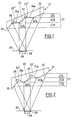
- FIG. 4 shows the use of a mirror (51) for irradiating the surface of a workpiece (59) in a linear work area (58) on the axis of rotation (50) of the mirror (51).
- the light bundle (57) is neither parallel nor axially parallel to the axis of rotation (50) but divergent with a source point (60) on the axis of rotation (50), so it is by the five segments (52-56) of the mirror (51) on the linear Work area (58) is shown, wherein at the rear edges (52a'-56a ') of the segments (52-56) there is a jump in the image from the end of the work area (58) at the beginning.
- the working area (58) is an interval on the axis of rotation (50).
- the inclinations and lengths of the conical segments (52-56) are chosen so that the associated focal lines on the axis of rotation (50) are of the same length and have the same position.
- the suitable dimensions can be easily calculated using known numerical calculation methods.
- the mirror (51) like the mirrors (21, 31, 41) described in FIGS. 1-3, has a step-like structure, shading between the different mirror segments (52-56) by the front mirror segments (52-55) Intermediate pieces (52a-55a) are located.
- part of the rear segments (53-56) shown here by way of example on part (61) on segment (56), is shadowed by the front segments (52-55).
- the light beam (57) emanating from the source point (60) does not fall onto the mirror (51) in an axis-parallel manner, the advantages described above for FIGS. 1-3 are also present here.
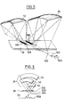
- FIGS. 5 and 6 illustrate a variant of the mirror (21) according to the invention, in which the segments (52, 53, 54) with their axes of rotation (522, 523, 524) are offset from one another step by step in parallel.
- 5 shows a perspective view
- FIG. 6 shows a front view together with a resulting intensity profile (500).
- Segments (52, 53, 54) of rotating bodies are now offset with their axes of rotation (522, 523, 524) laterally parallel to a central axis (520).
- the line foci (582, 583) of the individual segments (52, 53) lie on the respective axes of rotation (522, 523) in a rectangular area (528) on the object (29).
- An offset of 0.1 mm to 0.3 mm is typical.
- An offset by approximately the width of the individual line focus of the segments (52, 53, 54) is sufficient to suppress interference.
- a rectangular area with a targeted intensity profile can be illuminated. This is done by giving the adjacent individual lines different intensities.
- the intensities can be varied over the segment width or simply by taking advantage of the fact that the segments (52, 53, 54) are illuminated differently depending on the profile of the light beam (27).
- the offset for each segment (52, 53, 54) can be selected independently, as shown in FIG. 6.
- the segments (52, 53, 54) are drawn in with the same sector angles for clarification.
- the size of the sectors (52, 53, 54) should be selected so that the light beam (27) is fully covered and no gaps are created.
- offset is e.g. the vertical offset, which causes the contributions of the individual segments to be defocused, and the offset with tilting of the axes of rotation.
Abstract
Description
Die Erfindung betrifft einen Spiegel zur Veränderung der geometrischen Gestalt eines Lichtbündels sowie ein Verfahren zur Nutzung des Spiegels.The invention relates to a mirror for changing the geometric shape of a light beam and a method for using the mirror.
Spiegel zur Veränderung der geometrischen Gestalt eines Lichtbündels sind weit verbreitet. Schwierig ist die Erzeugung eines Strahlungsquerschnittes, welcher einen im wesentlichen linienförmigen bis rechteckigen Querschnitt aufweist, innerhalb dessen die Intensität einen vorbestimmten Verlauf hat, insbesondere in Längsrichtung konstant ist. Solche Strahlungsquerschnitte werden insbesondere zur Oberflächenbehandlung mit Lasern benötigt, um nur ein wesentliches Anwendungsgebiet zu nennen.Mirrors for changing the geometric shape of a light beam are widely used. It is difficult to generate a radiation cross section which has an essentially linear to rectangular cross section, within which the intensity has a predetermined course, in particular is constant in the longitudinal direction. Such radiation cross sections are required in particular for surface treatment with lasers, to name just one essential area of application.
In der früheren Patentanmeldung DE 39 12 237, US Ser. No. 07/505 177 desselben Erfinders und derselben Anmelderin, welche nach dem Prioritätstag dieser Anmeldung veröffentlicht wurde, ist ein derartiger Spiegel beschrieben.In the earlier patent application DE 39 12 237, US Ser. No. Such a mirror is described in 07/505 177 by the same inventor and the same applicant, which was published after the priority date of this application.
Die umformende Optik sorgt dafür, daß der Laserstrahl beim Auftreffen auf das Werkstück einen im wesentlichen rechteckigen bis linienförmigen Querschnitt aufweist, innerhalb dessen die Intensität einen fast konstanten Wert hat. Wird ein Strahl mit derartigem Querschnitt mit konstanter Geschwindigkeit und parallel zu einem Kantenpaar des Rechtecks über die Werkstückoberfläche geführt, dann ist das Energieprofil innerhalb des bestrahlten Streifens gleichförmig.The shaping optics ensure that the laser beam has an essentially rectangular to linear cross section when it strikes the workpiece, within which the intensity has an almost constant value. If a beam with such a cross-section is guided over the workpiece surface at a constant speed and parallel to an edge pair of the rectangle, then the energy profile within the irradiated strip is uniform.
Die meisten in der Praxis verwendeten Laser liefern einen Strahl, dessen Querschnitt nicht rechteckig und dessen Intensitätsverteilung nicht gleichförmig ist. Deshalb werden optische Anordnungen gebraucht, die einen beliebigen Strahlquerschnitt geeignet umformen können. Facettenspiegel und Integratoren sind zwei Typen von umformenden Optiken, welche für die Erzeugung von linienhaften Geometrien hinsichtlich der Intensitätsverteilung von Laserstrahlen bevorzugt eingesetzt werden.Most lasers used in practice deliver a beam whose cross-section is not rectangular and whose intensity distribution is not uniform. For this reason, optical arrangements are needed that can suitably transform any beam cross-section. Faceted mirrors and integrators are two types of reshaping optics, which are preferred for the generation of linear geometries with regard to the intensity distribution of laser beams.
In der JP 63-77178 A ist ein Facettenspiegel aus einer Vielzahl von Planspiegeln, die mosaikartig tangential an einer Paraboloidfläche anliegend angeordnet sind und ein Laserbündel auf ein Rechteck mit im wesentlichen der Ausdehnung eines einzelnen Planspiegels konzentrieren, beschrieben. Ein Linienprofil ist damit nicht erreichbar, da die einzelnen Spiegel keine fokussierende Wirkung haben. Die Fertigung einer solchen Anordnung ist kompliziert.JP 63-77178 A describes a facet mirror made up of a multiplicity of plane mirrors which are arranged in a mosaic-like manner tangentially against a paraboloid surface and which concentrate a laser beam on a rectangle with essentially the extent of a single plane mirror. A line profile cannot be reached because the individual mirrors have no focusing effect. The manufacture of such an arrangement is complicated.
Facettenspiegel sind auch aus Ream, S. L, "A Convex Beam Integrator", Laser Focus, Nov. 1979, pp. 68-71, US 4 518 232 und JP 59-151 101 A, letzterer mit sphärischen Facetten, bekannt.Faceted mirrors are also from Ream, S. L, "A Convex Beam Integrator", Laser Focus, Nov. 1979, pp. 68-71, US 4,518,232 and JP 59-151 101 A, the latter with spherical facets, are known.
Aufgabe der Erfindung ist es, mit nur einer optischen Abbildung einem Lichtbündel mit beliebigem Strahlquerschnitt einen linienförmigen bis rechteckigen Strahlquerschnitt mit bestimmter Intensitätsverteilung zu geben, wobei die Auswirkungen der bei längeren Wellenlängen auftretenden Interferenzen möglichst gering gehalten werden. Die exakte Herstellung soll durch die Eignung für inhärent genaue Fertigungsmethoden erleichtert sein.The object of the invention is to give a light beam with any beam cross section a linear to rectangular beam cross section with a certain intensity distribution with only one optical image, the effects of the interference occurring at longer wavelengths being kept as low as possible. The exact manufacture should be facilitated by the suitability for inherently precise manufacturing methods.
Diese Aufgabe wird gemäß den Merkmalen des Anspruchs 1 dadurch gelöst, daß der Spiegel ausgeführt ist aus mehreren aneinandergereihten Segmenten von Rotationskörpern, deren Rotationsachsen sich in einem linienförmigen bis rechteckigen Bereich eines Objekts zumindest annähernd überlagern, deren Größe so gewählt ist, daß das umzuformende Lichtbündel gleichzeitig auf mehrere der Segmente fällt und alle Segmente so geformt und ausgerichtet sind, daß jeweils eine Zone des Lichtbündels genau einmal durch ein Segment reflektiert wird und auf einen Ausschnitt des linienförmigen bis rechteckigen Bereichs des Objekts gerichtet wird, in dem sich die Rotationsachsen annähernd überlagern und auf diesem Ausschnitt alle Zonen des Lichtbündels zumindest näherungsweise überlagert werden, wobei die einzelnen Segmente stufenweise gegeneinander versetzt sind.This object is achieved according to the features of claim 1 in that the mirror is made up of a plurality of segments of rotating bodies lined up, the axes of rotation of which at least approximately overlap in a linear to rectangular area of an object, the size of which is selected such that the light beam to be reshaped at the same time falls on several of the segments and all segments are shaped and aligned such that a zone of the light beam is reflected exactly once by a segment and is directed at a section of the linear to rectangular area of the object, in which the axes of rotation overlap and open approximately All zones of the light bundle are at least approximately superimposed on this section, the individual segments being offset from one another in steps.
Durch die anamorphotische Wirkung der rotationssymmetrischen Spiegelsegmente wird mit wenigen Segmenten eine starke Konzentration möglich. Die Spiegelflächen sind Rotationsflächen, die inhärent exakter zu fertigen sind als Planflächen.Due to the anamorphic effect of the rotationally symmetrical mirror segments, a strong concentration is possible with just a few segments. The mirror surfaces are surfaces of revolution that are inherently more precisely manufactured than plane surfaces.
Der besondere Vorteil dieses Spiegel besteht darin, daß das Lichtbündel in mehrere streifenförmige Bereiche zerlegt wird, welche übereinandergelegt auf eine Linie gelenkt werden, wobei hierzu nur eine einzige Spiegelung jedes Lichtstrahlbereiches erfolgt. Diese optische Umformung der Strahlgeometrie kann eine hervorragende Homogenität der Intensitätsverteilung liefern, welche durch die Anzahl der Spiegelsegmente beeinflußbar ist, bei minimalen Energieverlusten bei der optischen Abbildung.The particular advantage of this mirror is that the light beam is broken down into several strip-shaped areas, which are superimposed and directed onto a line, with only a single reflection of each light beam area being performed for this purpose. This optical transformation of the beam geometry can provide an excellent homogeneity of the intensity distribution, which can be influenced by the number of mirror segments, with minimal energy losses in the optical imaging.
Bis auf den Versatz der Segmente und Symmetrieachsen entsprechen erfindungsgemäße Spiegel im Aufbau den in DE 39 12 237 A angegebenen.Except for the offset of the segments and axes of symmetry, mirrors according to the invention correspond in structure to those specified in DE 39 12 237 A.
Durch den stufenförmigen Versatz der Segmente werden die Kohärenzbedingungen für die Lichtbeiträge von den einzelnen Segmenten soweit verändert, daß Interferenzeffekte unterdrückt werden.The step-like offset of the segments changes the coherence conditions for the light contributions from the individual segments to such an extent that interference effects are suppressed.
Durch den axialen stufenförmigen Versatz nach Anspruch 2 erreicht man, daß die von benachbarten Segmenten zum Linienfokus hin reflektierten Strahlen einen größeren Winkel miteinander einschließen. Dadurch werden im Linienfokus entstehende axiale Interferenzstrukturen feiner strukturiert und sind dadurch für die erwähnten Anwendungsfälle weniger störend.The axial step-shaped offset according to claim 2 means that the rays reflected from adjacent segments towards the line focus enclose a larger angle with one another. As a result, axial interference structures that arise in the line focus are structured more finely and are therefore less disruptive for the mentioned use cases.
Werden die Segmente gemäß Anspruch 3 mit ihren Rotationsachsen parallel seitwärts stufenweise gegeneinander versetzt, dann lassen sich die Interferenzen praktisch völlig vermeiden. Bei weiter vergrößertem seitwärtigem Versatz wird der Überlagerungsbereich rechteckig und gemäß Anspruch 4 kann senkrecht zu den Rotationsachsen, im Fall der Anwendung bei der Laserbearbeitung in Vorschubrichtung, ein bestimmtes Intensitätsprofil erzeugt werden durch die Vorgabe des Versatzes der Segmente zu je bestimmten Zonen des Lichtbündels mit unterschiedlicher Gesamtintensität.Are the segments according to claim 3 with their axes of rotation offset parallel to one another step by step, then the interference can practically be completely avoided. If the lateral offset is further enlarged, the overlapping area becomes rectangular and, according to claim 4, a specific intensity profile can be generated perpendicular to the axes of rotation, in the case of use in laser processing in the feed direction, by specifying the offset of the segments to different zones of the light bundle with different overall intensities .
Ansprüche 5 bis 9 betreffen weitere vorteilhafte Ausführungsformen.Claims 5 to 9 relate to further advantageous embodiments.
Anspruch 10 betrifft ein Verfahren zur Oberflächenbehandlung mit Laser und Spiegel nach einem der Ansprüche 1 bis 9.Claim 10 relates to a method for surface treatment with laser and mirror according to one of claims 1 to 9.
Die in der obengenannten DE 39 12 237 A beschriebenen Eigenschaften und Vorteile sind auch dem erfindungsgemäßen Spiegel zu eigen, weshalb die dortige Offenbarung insgesamt Teil dieser Beschreibung ist.The properties and advantages described in the above-mentioned DE 39 12 237 A are also inherent in the mirror according to the invention, which is why the disclosure there is part of this description.
Die Erfindung wird nachstehend in beispielhafter Weise anhand der Figuren näher erläutert, wobei weitere wesentliche Merkmale sowie dem besseren Verständnis dienende Erläuterungen und Ausgestaltungsmöglichkeiten des Erfindungsgedankens beschrieben sind.The invention is explained in more detail below by way of example with reference to the figures, wherein further essential features and explanations and configuration options of the concept of the invention which serve to improve understanding are described.
Dabei zeigt
- Figur 1 einen Querschnitt durch einen erfindungsgemäßen Spiegel mit axial versetzten konischen Segmenten und parallelem Lichteinfall;
- Figur 2 einen Querschnitt durch einen erfindungsgemäßen Spiegel mit axial versetzten konvexen Segmenten und parallelem Lichteinfall;
- Figur 3 einen Querschnitt durch einen erfindungsgemäßen Spiegel mit axial versetzten konkaven Segmenten und parallelem Lichteinfall;
- Figur 4 einen Querschnitt durch einen erfindungsgemäßen Spiegel mit axial versetzten konischen Segmenten und divergentem Lichteinfall;
- Figur 5 ein perspektivisches Schema eines erfindungsgemäßen Spiegels mit seitlichem stufenförmigem Versatz der Segmente;
- Figur 6 eine schematische vereinfachte Ansicht eines erfindungsgemäßen Spiegels mit seitlichem stufenförmigem Versatz der Segmente einschließlich zugehörigem Intensitätsprofil.
- 1 shows a cross section through a mirror according to the invention with axially offset conical segments and parallel incidence of light;
- FIG. 2 shows a cross section through a mirror according to the invention with axially offset convex segments and parallel incidence of light;
- Figure 3 shows a cross section through a mirror according to the invention with axially offset concave segments and parallel incidence of light;
- Figure 4 shows a cross section through a mirror according to the invention with axially offset conical segments and divergent incidence of light;
- Figure 5 is a perspective diagram of a mirror according to the invention with lateral step-like offset of the segments;
- Figure 6 is a schematic simplified view of a mirror according to the invention with lateral step-like offset of the segments including the associated intensity profile.
Figur 1 zeigt einen Spiegel (21), der ein einfallendes Lichtbündel (27) auf einen linienförmigen Bereich (28) eines Objekts (29) abbildet. Der linienförmige Bereich (28) liegt auf der gemeinsamen Rotationsachse (20) der konischen Spiegel-Segmente (22, 23, 24). Die Segmente (22, 23, 24) sind nach Zahl, Größe, Achsabstand und Öffnungswinkel des Kegels so gewählt, daß jedes Segment (22, 23, 24) eine Zone des einfallenden Lichtbündels (27) durch einmalige Reflektion auf den für alle gleichen linienförmigen Bereich (28) als Linienfokus abbildet und daß das gesamte einfallende Lichtbündel (27) erfaßt wird.FIG. 1 shows a mirror (21) which images an incident light bundle (27) on a linear region (28) of an object (29). The linear region (28) lies on the common axis of rotation (20) of the conical mirror segments (22, 23, 24). The segments (22, 23, 24) are selected according to the number, size, center distance and opening angle of the cone so that each segment (22, 23, 24) is a zone of the incident light beam (27) by one-time reflection on the same linear for all Area (28) maps as a line focus and that the entire incident light beam (27) is detected.
Soweit ist dies aus der DE 39 12 237 A bekannt. Durch Einfügung von abgeschatteten Zwischenstücken (23a, 24a) beliebiger Kontur ist jedoch ein stufenweiser axialer Versatz der einzelnen Segmente (22, 23, 24) gegeneinander eingeführt.As far as this is known from DE 39 12 237 A. By inserting shaded intermediate pieces (23a, 24a) of any contour, however, a gradual axial offset of the individual segments (22, 23, 24) against each other is introduced.
Durch diese Maßnahme werden die Winkel zwischen den von den einzelnen Segmenten (22, 23, 24) auf den linienförmigen Bereich (28) auftreffenden Lichtbündeln erhöht und so werden Interferenzen zwischen diesen Bündeln enger strukturiert und damit weniger störend.As a result of this measure, the angles between the light beams striking the linear region (28) from the individual segments (22, 23, 24) are increased, and so interference between these beams is structured more closely and is therefore less disruptive.
Die zwischen den Spiegel-Segmenten (22, 23, 24) angeordneten Zwischenstücke (23a, 24a) sind so ausgeführt, daß sie einschließlich eines kleinen Bereichs (25) des jeweils nachfolgenden Segments (22, 23) durch die Kanten (23a ', 24a ') des jeweils voranliegenden Segments (23, 24) vom einfallenden Lichtbündel (27) abgeschattet werden.The intermediate pieces (23a, 24a) arranged between the mirror segments (22, 23, 24) are designed in such a way that they include a small area (25) of the respectively following segment (22, 23) through the edges (23a ', 24a ') of the respectively preceding segment (23, 24) are shadowed by the incident light beam (27).
Der Spiegel kann aus den einzelnen Segmenten (22, 23, 24) und Zwischenringen (23a, 24a) zusammengesetzt werden.The mirror can be assembled from the individual segments (22, 23, 24) and intermediate rings (23a, 24a).
Man kann den Spiegel aber auch problemlos aus einem Stück herausarbeiten, z.B. durch Diamantdrehen. Die benötigten Drehwerkzeuge für die Herstellung (z.B. Einzeldiamanten) eines erfindungsgemäßen Spiegels (21) haben immer verrundete Schneidkanten. Deshalb können spitze Vertiefungen (22 ', 23 ') wie sie in Figur 1 an den Anschlußstellen zwischen den Segmenten (22, 23, 24) und den Zwischenstücken (23a, 24a) auftreten, nur unvollkommen realisiert werden. Die hervorstehenden spitzen Kanten (23a ', 24 ') sind hingegen auch mit verrundetem Werkzeug exakt zu fertigen. Da aber die spitzen Vertiefungen (22 ', 23 ') im abgeschatteten Bereich der vorderen Segmente (23, 24) liegen und damit nicht am Abbildungsprozeß beteiligt sind, kommt es auf ihre exakte Herstellung nicht an.You can also easily work the mirror out of one piece, e.g. by diamond turning. The turning tools required for the production (e.g. individual diamonds) of a mirror (21) according to the invention always have rounded cutting edges. Therefore, pointed depressions (22 ', 23') as they occur in FIG. 1 at the connection points between the segments (22, 23, 24) and the intermediate pieces (23a, 24a) can only be realized incompletely. The protruding pointed edges (23a ', 24'), on the other hand, can also be manufactured precisely with rounded tools. However, since the pointed depressions (22 ', 23') lie in the shaded area of the front segments (23, 24) and are therefore not involved in the imaging process, their exact manufacture is not important.
In den Figuren 2 und 3 sind die spiegelnden Segmente (32, 33, 34) bzw. (42, 43, 44) gekrümmt, und zwar in Figur 2 konvex und in Figur 3 konkav. Sonst sind die Spiegel (31, 41) gleich aufgebaut wie der Spiegel (21) nach Figur 1 und gleiche Bezugszeichen bezeichnen gleiche Teile.In FIGS. 2 and 3, the reflecting segments (32, 33, 34) and (42, 43, 44) are curved, specifically convex in FIG. 2 and concave in FIG. 3. Otherwise, the mirrors (31, 41) are constructed in the same way as the mirror (21) according to FIG. 1 and the same reference numerals designate the same parts.
Bei den Spiegeln (31, 41) mit gekrümmten verspiegelten Segmenten (32, 33, 34; 42, 43, 44) (Figur 2, 3) hat man den Vorteil, daß man die Zahl (und damit die Länge) der Segmente (32, 33, 34; 42, 43, 44) einerseits und die Länge des linienförmigen Bereichs (28) andererseits unabhängig voneinander wählen kann.The advantage of mirrors (31, 41) with curved mirrored segments (32, 33, 34; 42, 43, 44) (FIGS. 2, 3) is that the number (and thus the length) of the segments (32 , 33, 34; 42, 43, 44) on the one hand and the length of the linear region (28) on the other hand independently of can choose each other.
Entsprechend der gewünschten Anwendungen und den gestellten Anforderungen an die Intensitätsverteilung haben die Segmente (32, 33, 34; 42, 43, 44) in Fig. 2, 3 in Richtung der Rotationsachse bevorzugt einen kreis-, parabel- oder elliptischen Querschnitt, so daß Torus-, Kugel-, Paraboloid-oder Ellipsoid-Flächen als spiegelnde Segmente (32, 33, 34; 42, 43, 44) entstehen. Für spezielle Intensitätsverteilungen in Richtung der Rotationsachsen können auch abweichende Formen zweckmäßig sein.According to the desired applications and the requirements placed on the intensity distribution, the segments (32, 33, 34; 42, 43, 44) in FIGS. 2, 3 preferably have a circular, parabolic or elliptical cross section in the direction of the axis of rotation, so that Toroidal, spherical, paraboloid or ellipsoid surfaces are created as reflecting segments (32, 33, 34; 42, 43, 44). Different shapes can also be appropriate for special intensity distributions in the direction of the axes of rotation.
Bei entsprechender Berechnung der Spiegel (21, 31, 41) können dabei die Einfallswinkel des Laserstrahlbündels (27) sowie dessen geometrische Eigenschaften in einem weiten Bereich variieren.If the mirrors (21, 31, 41) are calculated accordingly, the angle of incidence of the laser beam (27) and its geometric properties can vary within a wide range.
In Fig. 4 ist die Verwendung eines Spiegels (51) zur Bestrahlung der Oberfläche eines Werkstückes (59) in einem linienhaften Arbeitsbereich (58) auf der Rotationsachse (50) des Spiegels (51) gezeigt. Das Lichtbündel (57) ist dabei weder parallel noch achsparallel zur Rotationsachse (50) sondern divergent mit einem Quellpunkt (60) auf der Rotationsachse (50), wird also durch die fünf Segmente (52-56) des Spiegels (51) auf den linienhaften Arbeitsbereich (58) abgebildet, wobei an den hinteren Kanten (52a'-56a ') der Segmente (52-56) jeweils ein Sprung der Abbildung vom Ende des Arbeitsbereiches (58) an dessen Anfang erfolgt. Der Arbeitsbereich (58) ist dabei ein Intervall auf der Rotationsachse (50). Neigungen und Längen der kegeligen Segmente (52-56) werden so gewählt, daß die zugehörigen Fokallinien auf der Rotationsachse (50) gleich lang sind und die gleiche Lage haben. Die geeigneten Abmessungen lassen sich mit bekannten numerischen Rechenverfahren leicht berechnen.4 shows the use of a mirror (51) for irradiating the surface of a workpiece (59) in a linear work area (58) on the axis of rotation (50) of the mirror (51). The light bundle (57) is neither parallel nor axially parallel to the axis of rotation (50) but divergent with a source point (60) on the axis of rotation (50), so it is by the five segments (52-56) of the mirror (51) on the linear Work area (58) is shown, wherein at the rear edges (52a'-56a ') of the segments (52-56) there is a jump in the image from the end of the work area (58) at the beginning. The working area (58) is an interval on the axis of rotation (50). The inclinations and lengths of the conical segments (52-56) are chosen so that the associated focal lines on the axis of rotation (50) are of the same length and have the same position. The suitable dimensions can be easily calculated using known numerical calculation methods.
Der Spiegel (51) ist, wie die in den Fig. 1 - 3 beschriebenen Spiegel (21, 31, 41), stufenförmig aufgebaut, wobei sich zwischen den verschiedenen Spiegelsegmenten (52-56) durch die vorderen Spiegelsegmente (52-55) abgeschattete Zwischenstücke (52a-55a) befinden. Auch bei diesem Spiegel (51) durch die vorderen Segmente (52-55) ein Teil der hinteren Segmente (53-56), hier beispielhaft am Teil (61) auf Segment (56) dargestellt, abgeschattet. Obwohl nun das vom Quellpunkt (60) ausgehende Lichtbündel (57) nicht achsparallel auf den Spiegel (51) fällt, hat man auch hier die vorab zu Fig. 1 - 3 geschilderten Vorteile.The mirror (51), like the mirrors (21, 31, 41) described in FIGS. 1-3, has a step-like structure, shading between the different mirror segments (52-56) by the front mirror segments (52-55) Intermediate pieces (52a-55a) are located. In this mirror (51) too, part of the rear segments (53-56), shown here by way of example on part (61) on segment (56), is shadowed by the front segments (52-55). Although the light beam (57) emanating from the source point (60) does not fall onto the mirror (51) in an axis-parallel manner, the advantages described above for FIGS. 1-3 are also present here.
Die Figuren 5 und 6 illustrieren eine Variante des erfindungsgemäßen Spiegels (21), bei dem die Segmente (52, 53, 54) mit ihren Rotationsachsen (522, 523, 524) parallel seitwärts stufenweise gegeneinander versetzt sind. Figur 5 zeit eine perspektivische Sicht, Figur 6 eine Frontalansicht zusammen mit einem resultierenden Intensitätsprofil (500).FIGS. 5 and 6 illustrate a variant of the mirror (21) according to the invention, in which the segments (52, 53, 54) with their axes of rotation (522, 523, 524) are offset from one another step by step in parallel. 5 shows a perspective view, FIG. 6 shows a front view together with a resulting intensity profile (500).
Segmente (52, 53, 54) von Rotationskörpern, wie in den voranstehenden Figuren, sind nun mit ihren Rotationsachsen (522, 523, 524) gegenüber einer mittleren Achse (520) seitwärts parallel versetzt. Die Linienfoci (582, 583) der einzelnen Segmente (52, 53) liegen auf den jeweiligen Rotationsachsen (522, 523) in einem rechteckigen Bereich (528) auf dem Objekt (29). Typisch ist ein Versatz von 0,1 mm bis 0,3 mm. Zur Unterdrückung von Störinterferenzen genügt ein Versatz um etwa die Breite der einzelnen Linienfoci der Segmente (52, 53, 54). Bei größerem Versatz kann man einen rechteckigen Bereich mit gezieltem Intensitätsprofil ausleuchten. Dies geschieht dadurch, daß man den nebeneianderliegenden einzelnen Linien unterschiedliche Intensitäten gibt. Die Variation der Intensitäten kann über die Segmentbreite erfolgen oder einfach durch Ausnutzung der Tatsache, daß die Segmente (52, 53, 54) je nach dem Profil des Lichtbündels (27) unterschiedlich ausgeleuchtet werden. Dabei hat man gewisse Freiheiten deshalb, weil benachbarte Linien (582, 583) nicht notwendig von benachbarten Segmenten (52, 53, 54) erzeugt werden müssen. Der Versatz für jedes Segment (52, 53, 54) kann unabhängig gewählt werden, wie in Fig. 6 dargestellt.Segments (52, 53, 54) of rotating bodies, as in the previous figures, are now offset with their axes of rotation (522, 523, 524) laterally parallel to a central axis (520). The line foci (582, 583) of the individual segments (52, 53) lie on the respective axes of rotation (522, 523) in a rectangular area (528) on the object (29). An offset of 0.1 mm to 0.3 mm is typical. An offset by approximately the width of the individual line focus of the segments (52, 53, 54) is sufficient to suppress interference. With a larger offset, a rectangular area with a targeted intensity profile can be illuminated. This is done by giving the adjacent individual lines different intensities. The intensities can be varied over the segment width or simply by taking advantage of the fact that the segments (52, 53, 54) are illuminated differently depending on the profile of the light beam (27). One has certain freedoms because adjacent lines (582, 583) do not necessarily have to be generated by adjacent segments (52, 53, 54). The offset for each segment (52, 53, 54) can be selected independently, as shown in FIG. 6.
Die Grenzen ergeben sich dadurch, daß die Zahl der Segmente (52, 53, 54) und damit die Zahl der nebeneinanderliegenden Linien (582, 583) klein gehalten werden muß, damit nicht der Intensitätsabfall an den Enden der Linien (582, 583) durch Beugungserscheinungen zu stark verflacht wird.The limits result from the fact that the number of segments (52, 53, 54) and thus the number of adjacent lines (582, 583) must be kept small so that the drop in intensity at the ends of the lines (582, 583) does not Diffraction symptoms are flattened too much.
In Fig. 6 sind die Segmente (52, 53, 54) zur Verdeutlichung mit gleichen Sektorenwinkeln eingezeichnet. Natürlich ist aber wie in den vorangegangenen Beispielen die Größe der Sektoren (52, 53, 54) so zu wählen, daß das Lichtbündel (27) voll erfaßt wird und keine Lücken entstehen.6, the segments (52, 53, 54) are drawn in with the same sector angles for clarification. Of course, as in the previous examples, the size of the sectors (52, 53, 54) should be selected so that the light beam (27) is fully covered and no gaps are created.
Die Herstellung solcher Spiegel (21) mit seitlichem Versatz der Rotationsachsen wird realisiert durch Versetzen des Spiegelkörpers in der Halterung der Drehmaschine nach dem Fertigdrehen jedes einzelnen Segments (52, 53, 54).The manufacture of such mirrors (21) with lateral offset of the axes of rotation is realized by displacing the mirror body in the holder of the lathe after each individual segment (52, 53, 54) has been turned.
Andere Formen des Versatzes sind z.B. der vertikale Versatz, der eine Defokussierung der Beiträge der einzelnen Segmente bewirkt, und der Versatz mit Kippung der Rotationsachsen.Other forms of offset are e.g. the vertical offset, which causes the contributions of the individual segments to be defocused, and the offset with tilting of the axes of rotation.
Claims (10)
Applications Claiming Priority (2)
| Application Number | Priority Date | Filing Date | Title |
|---|---|---|---|
| DE4023904A DE4023904A1 (en) | 1990-07-27 | 1990-07-27 | MIRROR FOR CHANGING THE GEOMETRIC DESIGN OF A BUNCH OF LIGHT |
| DE4023904 | 1990-07-27 |
Publications (2)
| Publication Number | Publication Date |
|---|---|
| EP0468328A1 true EP0468328A1 (en) | 1992-01-29 |
| EP0468328B1 EP0468328B1 (en) | 1996-03-20 |
Family
ID=6411148
Family Applications (1)
| Application Number | Title | Priority Date | Filing Date |
|---|---|---|---|
| EP91111740A Expired - Lifetime EP0468328B1 (en) | 1990-07-27 | 1991-07-15 | Mirror for altering the geometric shape of a light beam |
Country Status (4)
| Country | Link |
|---|---|
| US (1) | US5148326A (en) |
| EP (1) | EP0468328B1 (en) |
| JP (1) | JPH04251802A (en) |
| DE (2) | DE4023904A1 (en) |
Cited By (7)
| Publication number | Priority date | Publication date | Assignee | Title |
|---|---|---|---|---|
| EP0630720A1 (en) * | 1993-06-25 | 1994-12-28 | Honda Giken Kogyo Kabushiki Kaisha | Optical system for laser beam generator |
| US5690845A (en) * | 1994-10-07 | 1997-11-25 | Sumitomo Electric Industries, Ltd. | Optical device for laser machining |
| WO1998008128A1 (en) * | 1996-08-16 | 1998-02-26 | Fraunhofer-Gesellschaft zur Förderung der angewandten Forschung e.V. | Arrangement for geometrically shaping a radiation field |
| WO2007093436A1 (en) * | 2006-02-17 | 2007-08-23 | Carl Zeiss Smt Ag | Optical integrator for an illumination system of a microlithographic projection exposure apparatus |
| WO2007098777A1 (en) * | 2006-02-24 | 2007-09-07 | Trumpf Werkzeugmaschinen Gmbh +Co. Kg | Mirror arrangement of a laser machining unit comprising a mirror having at least two mirror regions and a shadow zone |
| US8395756B2 (en) | 2006-02-17 | 2013-03-12 | Carl Zeiss Smt Gmbh | Illumination system for a microlithographic projection exposure apparatus |
| CN109759799A (en) * | 2019-03-12 | 2019-05-17 | 西北核技术研究所 | A kind of processing method rotating the non-rotating reflecting surface structure of semielliptical |
Families Citing this family (21)
| Publication number | Priority date | Publication date | Assignee | Title |
|---|---|---|---|---|
| US5285320A (en) * | 1989-04-14 | 1994-02-08 | Carl-Zeiss-Stiftung | Mirror for changing the geometrical form of a light beam |
| JP2829192B2 (en) * | 1992-05-15 | 1998-11-25 | 住友電気工業株式会社 | Laser beam scanner |
| JP2655465B2 (en) * | 1993-01-20 | 1997-09-17 | 日本電気株式会社 | Reflection type homogenizer and reflection type illumination optical device |
| DE4314601C2 (en) * | 1993-05-04 | 1996-08-08 | Fraunhofer Ges Forschung | Device and method for treating grain-oriented workpieces using focused light |
| US5397327A (en) * | 1993-07-27 | 1995-03-14 | Coherent, Inc. | Surgical laser handpiece for slit incisions |
| DE19514624C2 (en) * | 1995-04-26 | 1997-03-27 | Fraunhofer Ges Forschung | Arrangement for shaping the geometric cross section of a radiation field of one or more gas lasers |
| DE19514625C2 (en) * | 1995-04-26 | 1997-03-06 | Fraunhofer Ges Forschung | Arrangement for forming the geometric cross section of a radiation field of one or more solid-state and / or semiconductor lasers |
| DE19514626C2 (en) * | 1995-04-26 | 1997-03-06 | Fraunhofer Ges Forschung | Arrangement for shaping the geometric cross section of a radiation field of one or more solid-state and / or semiconductor lasers |
| GB2313206A (en) * | 1996-05-17 | 1997-11-19 | Crowcon Detection Instr Limite | Optical component for distributing radiation to foci |
| FR2753522B1 (en) * | 1996-09-19 | 1998-12-04 | Valeo Vision | MOTOR VEHICLE SIGNALING LIGHT COMPRISING A MIRROR WITH IMPROVED DEVIATOR PAVES |
| DE19805726A1 (en) * | 1998-02-12 | 1999-09-02 | Fraunhofer Ges Forschung | Method of increasing the process stability of laser material processing |
| US6324320B1 (en) | 1998-03-17 | 2001-11-27 | Polaroid Corporation | Optical apparatus for producing a high-brightness multi-laser radiation source |
| US6075912A (en) * | 1998-03-17 | 2000-06-13 | Polaroid Corporation | Apparatus for coupling radiation beams into an optical waveguide |
| JP2001244213A (en) * | 1999-12-24 | 2001-09-07 | Semiconductor Energy Lab Co Ltd | Laser beam irradiating device and method of manufacturing semiconductor device |
| US6856630B2 (en) * | 2000-02-02 | 2005-02-15 | Semiconductor Energy Laboratory Co., Ltd. | Beam homogenizer, laser irradiation apparatus, semiconductor device, and method of fabricating the semiconductor device |
| PT102735A (en) * | 2002-03-05 | 2003-09-30 | Ibe Ind De Bens De Equipamento | PROCESS AND MACHINE FOR CUTTING AND / OR WELDING AND / OR WRAPPING BODIES |
| JP2009514188A (en) * | 2003-07-09 | 2009-04-02 | カール・ツァイス・エスエムティー・アーゲー | Facet mirror and method of manufacturing mirror facet |
| DE10345430A1 (en) * | 2003-09-30 | 2005-06-02 | Carl Zeiss Sms Gmbh | lighting device |
| JP5234462B2 (en) * | 2009-01-21 | 2013-07-10 | 国立大学法人 東京大学 | Optical element and infrared sensor |
| US20110063205A1 (en) * | 2009-09-15 | 2011-03-17 | Motorola, Inc. | Display magnifier |
| DE102017100945B4 (en) | 2017-01-18 | 2019-06-27 | LIMO GmbH | Lens device or mirror device and device for homogenization of light |
Citations (3)
| Publication number | Priority date | Publication date | Assignee | Title |
|---|---|---|---|---|
| FR2525733A1 (en) * | 1982-04-23 | 1983-10-28 | Auteroche Sa | Headlamp reflector with sub-reflector to aim beam downwards - uses main reflector with stepped parabolic segments moulded in to deflect down part of light beam |
| US4518232A (en) * | 1983-08-24 | 1985-05-21 | Avco Everett Research Laboratory, Inc. | Method and apparatus for optical beam shaping |
| EP0395910A2 (en) * | 1989-04-29 | 1990-11-07 | Firma Carl Zeiss | Mirror for modification of the optical configuration of a light beam |
Family Cites Families (18)
| Publication number | Priority date | Publication date | Assignee | Title |
|---|---|---|---|---|
| US1919561A (en) * | 1929-04-29 | 1933-07-25 | Kogel Gustav | Concave mirror |
| CH160209A (en) * | 1930-09-23 | 1933-02-28 | Koegel Gustav Prof Ing Dr | Concave mirror for creating three-dimensional images. |
| US3613659A (en) * | 1968-10-14 | 1971-10-19 | Robert M Phillips | Solar-energy-concentrating device |
| US3523721A (en) * | 1968-12-09 | 1970-08-11 | Zeiss Jena Veb Carl | Spherically corrected fresnel lenses and mirrors with partial field correction |
| US3888589A (en) * | 1974-02-11 | 1975-06-10 | Pilkington Perkin Elmer Ltd | Reflection grating optical odometer |
| US4110009A (en) * | 1975-12-19 | 1978-08-29 | Bunch Jesse C | Heliostat apparatus |
| US4195913A (en) * | 1977-11-09 | 1980-04-01 | Spawr Optical Research, Inc. | Optical integration with screw supports |
| DE2808359C3 (en) * | 1978-02-27 | 1980-09-04 | Erwin Sick Gmbh Optik-Elektronik, 7808 Waldkirch | Finding device for holes in lanes |
| US4327972A (en) * | 1979-10-22 | 1982-05-04 | Coulter Electronics, Inc. | Redirecting surface for desired intensity profile |
| US4475027A (en) * | 1981-11-17 | 1984-10-02 | Allied Corporation | Optical beam homogenizer |
| US4484334A (en) * | 1981-11-17 | 1984-11-20 | Allied Corporation | Optical beam concentrator |
| JPS59151101A (en) * | 1983-02-08 | 1984-08-29 | Toshiba Corp | Concave mirror |
| GB8306951D0 (en) * | 1983-03-14 | 1983-04-20 | Ici Plc | Energy beam focusing apparatus |
| SU1171744A1 (en) * | 1984-02-07 | 1985-08-07 | Предприятие П/Я Г-4671 | Dispergating device |
| US4620230A (en) * | 1984-09-24 | 1986-10-28 | The Boeing Company | Display system |
| JPS6237350A (en) * | 1985-08-12 | 1987-02-18 | Toshiba Corp | Surface heat treating apparatus |
| JPS6377178A (en) * | 1986-09-19 | 1988-04-07 | Fanuc Ltd | Pumping reflector for laser |
| US4798446A (en) * | 1987-09-14 | 1989-01-17 | The United States Of America As Represented By The United States Department Of Energy | Aplanatic and quasi-aplanatic diffraction gratings |
-
1990
- 1990-07-27 DE DE4023904A patent/DE4023904A1/en not_active Withdrawn
-
1991
- 1991-07-15 DE DE59107565T patent/DE59107565D1/en not_active Expired - Fee Related
- 1991-07-15 EP EP91111740A patent/EP0468328B1/en not_active Expired - Lifetime
- 1991-07-29 US US07/737,448 patent/US5148326A/en not_active Expired - Lifetime
- 1991-07-29 JP JP3210455A patent/JPH04251802A/en active Pending
Patent Citations (3)
| Publication number | Priority date | Publication date | Assignee | Title |
|---|---|---|---|---|
| FR2525733A1 (en) * | 1982-04-23 | 1983-10-28 | Auteroche Sa | Headlamp reflector with sub-reflector to aim beam downwards - uses main reflector with stepped parabolic segments moulded in to deflect down part of light beam |
| US4518232A (en) * | 1983-08-24 | 1985-05-21 | Avco Everett Research Laboratory, Inc. | Method and apparatus for optical beam shaping |
| EP0395910A2 (en) * | 1989-04-29 | 1990-11-07 | Firma Carl Zeiss | Mirror for modification of the optical configuration of a light beam |
Non-Patent Citations (4)
| Title |
|---|
| APPLIED OPTICS Band 19, Nr. 20, 1980, Seiten 3554-3561, New York, US; B. AUTHIER et al.: "High concentration solar collector of the stepped spherical type: optical design characteristics" * |
| NAVY TECHNICAL DISCLOSURE BULLETIN Band 10, Nr. 4, 1985, Seiten 25-32, Arlington, Virginia, US; B.H. RIPIN: "Induced spatial incoherence optical delay element" * |
| OPTICAL ENGINEERING Band 27, Nr. 11, 1988, Seiten 999-1007; Bellingham, WA, US; F.M. DICKEY et al.: "Multifaceted laser beam integrators: general formulation and design concepts" * |
| PATENT ABSTRACTS OF JAPAN Band 8, Nr. 286 (P-324), 27. Dezember 1984; & JP - A - 59151101 (TOSHIBA) 29.08.1984 (Kat. D) * |
Cited By (13)
| Publication number | Priority date | Publication date | Assignee | Title |
|---|---|---|---|---|
| EP0630720A1 (en) * | 1993-06-25 | 1994-12-28 | Honda Giken Kogyo Kabushiki Kaisha | Optical system for laser beam generator |
| US5690845A (en) * | 1994-10-07 | 1997-11-25 | Sumitomo Electric Industries, Ltd. | Optical device for laser machining |
| WO1998008128A1 (en) * | 1996-08-16 | 1998-02-26 | Fraunhofer-Gesellschaft zur Förderung der angewandten Forschung e.V. | Arrangement for geometrically shaping a radiation field |
| US8520307B2 (en) | 2006-02-17 | 2013-08-27 | Carl Zeiss Smt Gmbh | Optical integrator for an illumination system of a microlithographic projection exposure apparatus |
| US7880969B2 (en) | 2006-02-17 | 2011-02-01 | Carl Zeiss Smt Ag | Optical integrator for an illumination system of a microlithographic projection exposure apparatus |
| US8395756B2 (en) | 2006-02-17 | 2013-03-12 | Carl Zeiss Smt Gmbh | Illumination system for a microlithographic projection exposure apparatus |
| WO2007093436A1 (en) * | 2006-02-17 | 2007-08-23 | Carl Zeiss Smt Ag | Optical integrator for an illumination system of a microlithographic projection exposure apparatus |
| US9217930B2 (en) | 2006-02-17 | 2015-12-22 | Carl Zeiss Smt Gmbh | Illumination system for a microlithographic projection exposure apparatus |
| US9575414B2 (en) | 2006-02-17 | 2017-02-21 | Carl Zeiss Smt Gmbh | Illumination system for a microlithographic projection exposure apparatus |
| WO2007098777A1 (en) * | 2006-02-24 | 2007-09-07 | Trumpf Werkzeugmaschinen Gmbh +Co. Kg | Mirror arrangement of a laser machining unit comprising a mirror having at least two mirror regions and a shadow zone |
| CN101394966B (en) * | 2006-02-24 | 2011-10-26 | 通快机床两合公司 | Mirror arrangement of a laser machining unit comprising a mirror having at least two mirror regions and a shadow zone |
| US8246185B2 (en) | 2006-02-24 | 2012-08-21 | Trumpf Werkzeugmaschinen Gmbh +Co. Kg | Mirror arrangement of a laser processing system |
| CN109759799A (en) * | 2019-03-12 | 2019-05-17 | 西北核技术研究所 | A kind of processing method rotating the non-rotating reflecting surface structure of semielliptical |
Also Published As
| Publication number | Publication date |
|---|---|
| DE59107565D1 (en) | 1996-04-25 |
| EP0468328B1 (en) | 1996-03-20 |
| JPH04251802A (en) | 1992-09-08 |
| US5148326A (en) | 1992-09-15 |
| DE4023904A1 (en) | 1992-01-30 |
Similar Documents
| Publication | Publication Date | Title |
|---|---|---|
| EP0468328A1 (en) | Mirror for altering the geometric shape of a light beam | |
| DE2908195C2 (en) | Device for processing a workpiece with a laser beam | |
| DE3734656C2 (en) | Method and device for producing lenses or similarly shaped objects by means of laser radiation | |
| DE2431265C2 (en) | Optical device for generating a very small beam | |
| DE112016002870T5 (en) | Optical element arrangements for modifying the beam parameter product in laser delivery systems | |
| DE4328894C2 (en) | Laser processing device and associated method | |
| DE3911443C2 (en) | Optical luminaire cover with Fresnel prisms, their use and a process for their manufacture | |
| EP0835715A1 (en) | Apparatus and method for laser processing a workpiece by means of a diode laser | |
| EP0395910B1 (en) | Mirror for modification of the optical configuration of a light beam | |
| EP2429755B1 (en) | Device and method for machining the circumference of a material strand by means of a laser | |
| EP3752314A1 (en) | Method and device for inserting a separation line into a transparent, brittle-fracture material, and element that can be produced according to the method and is provided with a separation line | |
| DE3418188C2 (en) | ||
| DE2927406A1 (en) | DEVICE FOR DRAWING GRILLE LINES | |
| WO2003016963A2 (en) | Arrangement and device for optical beam homogenization | |
| DE19752416A1 (en) | Method and device for combining the radiation power of a linear arrangement of radiation sources | |
| DE3912237A1 (en) | MIRROR FOR CHANGING THE GEOMETRIC DESIGN OF A BUNCH OF LIGHT | |
| DE19846368C1 (en) | Apparatus for cutting, welding, boring or removing a workpiece has a diffractive element made up of different segments to form focal points | |
| DE102019108681A1 (en) | Device and method for generating a double or multiple spot in laser material processing | |
| EP2675609B1 (en) | Process for selective laser melting and system for carrying out said process | |
| DE4219809A1 (en) | Material surface layers removal for precision and less complicated system - by successive radiation of parts of surface with optical element system in electromagnetic beam path for constant area cross=section maintenance | |
| DE6806092U (en) | OPTICAL SYSTEM FOR FOCUSING A BUNCH OF MONOCHROTIC RAYS OF LIGHT EMITTED BY A PULSE LASER | |
| DE112017006002T5 (en) | Laser beam processing method and laser beam machine | |
| DE4018355C2 (en) | ||
| DE3530929C2 (en) | Device for the transmission of radiation energy | |
| CH304170A (en) | Reflection system. |
Legal Events
| Date | Code | Title | Description |
|---|---|---|---|
| PUAI | Public reference made under article 153(3) epc to a published international application that has entered the european phase |
Free format text: ORIGINAL CODE: 0009012 |
|
| AK | Designated contracting states |
Kind code of ref document: A1 Designated state(s): DE FR GB SE |
|
| 17P | Request for examination filed |
Effective date: 19920706 |
|
| 17Q | First examination report despatched |
Effective date: 19940803 |
|
| GRAH | Despatch of communication of intention to grant a patent |
Free format text: ORIGINAL CODE: EPIDOS IGRA |
|
| GRAA | (expected) grant |
Free format text: ORIGINAL CODE: 0009210 |
|
| AK | Designated contracting states |
Kind code of ref document: B1 Designated state(s): DE FR GB SE |
|
| ET | Fr: translation filed | ||
| REF | Corresponds to: |
Ref document number: 59107565 Country of ref document: DE Date of ref document: 19960425 |
|
| PGFP | Annual fee paid to national office [announced via postgrant information from national office to epo] |
Ref country code: GB Payment date: 19960613 Year of fee payment: 6 |
|
| PGFP | Annual fee paid to national office [announced via postgrant information from national office to epo] |
Ref country code: FR Payment date: 19960617 Year of fee payment: 6 |
|
| GBT | Gb: translation of ep patent filed (gb section 77(6)(a)/1977) |
Effective date: 19960522 |
|
| PGFP | Annual fee paid to national office [announced via postgrant information from national office to epo] |
Ref country code: SE Payment date: 19960619 Year of fee payment: 6 |
|
| PLBE | No opposition filed within time limit |
Free format text: ORIGINAL CODE: 0009261 |
|
| STAA | Information on the status of an ep patent application or granted ep patent |
Free format text: STATUS: NO OPPOSITION FILED WITHIN TIME LIMIT |
|
| 26N | No opposition filed | ||
| PG25 | Lapsed in a contracting state [announced via postgrant information from national office to epo] |
Ref country code: GB Free format text: LAPSE BECAUSE OF NON-PAYMENT OF DUE FEES Effective date: 19970715 |
|
| PG25 | Lapsed in a contracting state [announced via postgrant information from national office to epo] |
Ref country code: SE Effective date: 19970716 |
|
| GBPC | Gb: european patent ceased through non-payment of renewal fee |
Effective date: 19970715 |
|
| PG25 | Lapsed in a contracting state [announced via postgrant information from national office to epo] |
Ref country code: FR Free format text: LAPSE BECAUSE OF NON-PAYMENT OF DUE FEES Effective date: 19980331 |
|
| EUG | Se: european patent has lapsed |
Ref document number: 91111740.6 |
|
| REG | Reference to a national code |
Ref country code: FR Ref legal event code: ST |
|
| PGFP | Annual fee paid to national office [announced via postgrant information from national office to epo] |
Ref country code: DE Payment date: 20080722 Year of fee payment: 18 |
|
| PG25 | Lapsed in a contracting state [announced via postgrant information from national office to epo] |
Ref country code: DE Free format text: LAPSE BECAUSE OF NON-PAYMENT OF DUE FEES Effective date: 20100202 |