EP0466155B1 - System zur Lokalisierung von Fehlerstellen in einem elektrischen Leistungskabel mit Hilfe einer Anordnung zum Verlegen von optischen Fasern - Google Patents
System zur Lokalisierung von Fehlerstellen in einem elektrischen Leistungskabel mit Hilfe einer Anordnung zum Verlegen von optischen Fasern Download PDFInfo
- Publication number
- EP0466155B1 EP0466155B1 EP91111563A EP91111563A EP0466155B1 EP 0466155 B1 EP0466155 B1 EP 0466155B1 EP 91111563 A EP91111563 A EP 91111563A EP 91111563 A EP91111563 A EP 91111563A EP 0466155 B1 EP0466155 B1 EP 0466155B1
- Authority
- EP
- European Patent Office
- Prior art keywords
- optical fiber
- power cable
- electric power
- cable line
- portions
- Prior art date
- Legal status (The legal status is an assumption and is not a legal conclusion. Google has not performed a legal analysis and makes no representation as to the accuracy of the status listed.)
- Revoked
Links
Images


Classifications
-
- G—PHYSICS
- G01—MEASURING; TESTING
- G01R—MEASURING ELECTRIC VARIABLES; MEASURING MAGNETIC VARIABLES
- G01R31/00—Arrangements for testing electric properties; Arrangements for locating electric faults; Arrangements for electrical testing characterised by what is being tested not provided for elsewhere
- G01R31/08—Locating faults in cables, transmission lines, or networks
- G01R31/088—Aspects of digital computing
Definitions
- the present invention relates to a system for detecting a trouble occurrence location of an electric power cable line by using a distribution type temperature sensor and particularly a Raman backscattering optical fiber distribution type temperature sensor and, more particularly, to a structure in which an optical fiber of a temperature detector of a distribution type temperature sensor is laid along an electric power cable line.
- the Raman backscattering optical fiber distribution type temperature sensor can measure a temperature distribution in the longitudinal direction of an optical fiber of its temperature detector. When the optical fiber is laid along an electric power cable, a position on the electric power cable line where a temperature rises due to a trouble such as a ground-fault is detected to identify the trouble occurrence location.
- a principle of measuring a temperature distribution by the above-described Raman backscattering optical fiber distribution type temperature sensor is as below.
- the light When a light is incident into an optical fiber, the light is scattered due to the small fluctuation of a refractive index in the optical fiber, absorption, or re-emission of a light by molecules, atoms of the optical fiber.
- the scattered lights There are as the scattered lights a Rayleigh scattering light having the same wavelength as the incident light and a Raman backscattering light having a different wavelength from the incident light.
- the latter Raman backscattering light is generated by the thermal vibration of molecules, atoms of the optical fiber, and its intensity depends largely upon its temperature.
- the temperatures of the positions of the optical fiber in the respective directions can be measured.
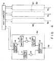
- an electric power cable line 1 has a plurality of unit cables 3A, 3B, 3C and 3D connected in series through joint portions 2A, 2B and 2C.
- the electric power cable line 1 is divided into a plurality of maintenance sections 4A to 4D at the intermediate positions of the joint portions 2A to 2C as boundaries at the respective unit cables 3A to 3D.
- Independent optical fibers 5A, 5B, 5C and 5D are respectively laid along the unit cables 3A, 3B, 3C and 3D at the unit cables 3A to 3D of the maintenance sections 4A to 4D.
- the ends of the optical fibers 5A to 5D are respectively connected to distribution type temperature sensor processing units 6A to 6D, which are, in turn, connected to a host computer 9.
- a temperature peak position on the electric power cable line i.e., an occurrence location of a trouble such as a ground-fault of the electric power cable line can be detected at each of the respective unit cables, i.e., the respective maintenance sections.
- the sections or persons in charge of maintenance and supervision are different in the respective maintenance sections along the electric power cable line as described above, it is necessary to know where a trouble is generated in the maintenance sections, and it is particularly necessary to accurately detect where a trouble occurs in the adjacent maintenance sections in the vicinity of the boundary between the maintenance sections.
- the boundary between the maintenance sections is frequently disposed at the joint portion of the unit cables.
- the occurrence frequency of a trouble such as a ground-fault at the joint portions of the unit cables is remarkably higher than that at the normal portion of the electric power cable. Therefore, it is strongly desired to improve the detecting accuracy of the trouble occurrence location of the joint portion of the unit cables.
- the Raman backscattering optical fiber distribution type temperature sensor can considerably accurately detect the temperature peak position due to its characteristics and an electric power cable line trouble occurrence location detecting system using the temperature sensor can considerably accurately detect the occurrence location of a trouble such as a ground-fault. However, it is not yet sufficient to accurately detect where the trouble occurrence location belongs to the section of which side in the vicinity of the boundary between the maintenance sections as described above, and it is not yet sufficient from the view of accurately detecting the trouble occurrence location at the joint portions of the unit cables having high trouble occurrence frequency.
- JP-A-59 131 177 shows a fault detector including a fibre excessive length storage part.
- an optical fiber laying structure for an electric power cable line trouble occurrence location detecting system for detecting a trouble occurrence location by laying an optical fiber of a temperature detector of a Raman backscattering optical fiber distribution type temperature sensor along an electric power cable line and detecting a temperature rising position of the power cable line, characterized in that; independent optical fibers are laid along said electric power cable line, and a portion of one of the optical fibers is superposed to be laid on a portion of an adjacent one of the optical fibers.
- the portion of the detecting optical fiber laid along the cable of one of the two adjacent sections is superposed on the portion of the optical fiber laid along the cable of the other sections in an area in the vicinity of the boundary (hereinafter referred to as "a boundary area") of the electric power cable line. Therefore, if a temperature rise occurs due to a trouble such as a ground-fault in the boundary area, the temperature peak position, i.e., the trouble occurrence location can be detected by the two different optical fibers. As described above, when the trouble occurrence location is detected by the two different optical fibers, its detecting accuracy is remarkably enhanced as compared with the case that the accident is detected by only one optical fiber.
- the temperature peak position obtained by one optical fiber is not always clearly present, it can be clarified by superposing the data from the two optical fibers, or even when the temperature peak position data obtained from the optical fiber is deviated from the true position, an error can be reduced by averaging the positional data obtained by the two optical fibers. Therefore, the trouble occurrence location in the boundary area can be accurately detected, and which of the sections the trouble occurrence location belongs to can be accurately determined.
- the portion of the detecting optical fiber laid along the one of the adjacent unit cables is superposed to be laid on the portion of the detecting optical fiber laid along the other of the unit cables at each of the joint portions of the electric power cable line having a plurality of unit cables connected in series through the joint portions. Therefore, when a temperature rise occurs due to a trouble such as a ground-fault at the joint portion of the unit cables, the temperature peak position, i.e., the trouble occurrence location is detected by the two different optical fibers, thereby accurately detecting the trouble occurrence location in the joint portion.
- the joint portions of the unit cables frequently become the boundary between the maintenance sections as already described above. Therefore, in this case, the detection of the trouble occurrence location in the boundary area by the two optical fibers in the first aspect of the present invention becomes equivalent to the detection of the trouble occurrence location in the joint portion by the two optical fibers in the second aspect of the present invention. In other words, in this case, the occurrence location of a trouble such as a ground-fault can be accurately detected in the portion of the boundary area as well as the joint portion.
- Fig. 2 schematically shows an entire arrangement of an embodiment according to first and second aspects of the present invention.
- an electric power cable line 1 has, similarly to the prior art shown in Fig. 1, a plurality of unit cables 3A to 3D connected in series through joint portions 2A, 2B and 2C.
- the electric power cable line 1 is divided into a plurality of maintenance sections 4A to 4D at the centers of the joint portions 2A to 2C as section boundaries 7A to 7C. Therefore, the joint portions 2A to 2C respectively become boundary areas 8A to 8C of the sections.
- Optical fibers 5A to 5D are respectively laid along the unit cables 3A to 3D of the maintenance sections 4A to 4D at the unit cables 3A to 3D.
- the optical fibers 5A to 5D are respectively connected to distribution type temperature sensor measuring units 6A to 6D, which are, in turn, connected to a host computer 9.
- the optical fibers 5A to 5D are respectively laid at the portions, i.e., end portions or the initial laying portions to be laid along the electric power cable line 1 along the joint portions 2A to 2C, i.e., the boundary areas 8A to 8C.
- two optical fibers are respectively laid along the joint portions 2A to 2C, i.e., the boundary areas 8A to 8C.
- the initial laying portions of both the optical fibers 5A and 5B or 5C and 5D to the electric power cable line 1 are superposed to be laid at the joint portion 2A (i.e., the section boundary area 8A) or the joint portion 2C (i.e., the section boundary area 8C) along the electric power cable line 1 as shown in Fig. 3A, and the ends of both the optical fibers 5B and 5C are superposed to be laid at the joint portion 2B (i.e., the section boundary area 8B) as shown in Fig. 3B.
- Arrangements of distribution type temperature sensor processing units 6A to 6D respectively connected to the optical fibers 5A to 5D may be the same as ordinary ones, and are normally formed as shown in Figs. 3A and 3B. More specifically, the processing units 6A to 6D emit laser pulse lights as incident lights to the optical fibers 5A to 5D, isolate Raman backscattering lights to be returned from the optical fibers, photodetect the Raman backscattering lights, amplify and average the same lights. As shown in Fig.
- each processing unit comprises a laser light source 10 for oscillating a laser light pulse as an incident light to the optical fiber, a driving circuit 11 for driving the laser light source 10, a branching unit 12 for separating a Raman backscattering light from reflected scattering light to be returned from each of the optical fibers 5A to 5D, a cut-off filter 13 for cutting off the light component except the Raman light in the Raman backscattering light, a photodetector 14 for converting the Raman backscattering light to be output from the cut-off filter 13 into an electric signal, an amplifier 15 for amplifying the electric signal from the photodetector 14, and an averaging circuit 16 for improving S/N ratio of the electric signal.
- the output signals from the respective processing units 6A to 6D are applied to the host computer 9, and a control signal from the host computer 9 is applied to each of the processing units 6.
- the host computer 9 calculates the output signals from the processing units 6A to 6D to obtain a temperature distribution in the longitudinal direction of the optical fibers 5A to 5D and to further obtain the temperature peak position, i.e., the occurrence location of a trouble such as a ground-fault.
- the host computer 9 calculates the data obtained by the signals from the portions of the two optical fibers and can accurately obtain the temperature peak position, i.e., the occurrence location of a trouble such as a ground-fault.
- the concrete arrangement in which the optical fibers 5A to 5D are respectively laid along the unit cables 3A to 3D and the joint portions 2A to 2C are optional.
- the optical fibers may be supported by suitable supporting means (not shown) to be linearly laid along the longitudinal direction of the unit cables and the joint portions or, as shown in Fig. 5, the optical fibers may be spirally wound on the electric power cable line 1.
- the fact that the portions of the two optical fibers are superposed to be laid along the joint portions 2A to 2C is not limited to the case that two optical fibers are superposed or arranged adjacently at the same side of the joint portions 2A to 2C.
- the boundaries 7A to 7C are disposed at the centers of the joint portions 2A to 2C.
- the present invention is not limited to the particular embodiment.
- the boundaries 7A to 7C may be disposed at the ends of the joint portions 2A to 2C.
- the boundary areas 8A to 8C may be normally determined, similarly to the embodiment described above, to be formed of the areas made of joint portions 2A to 2C.
- areas including the portions at both sides of the boundaries 7A to 7C of the ends of the joint portions 2A to 2C, i.e., areas including both the joint portions and the ends of the unit cables connected to the joint portions may be determined as section areas.
- boundaries 7A to 7C may be set at individually independent positions from the joint portions 2A to 2C.
- the boundary areas 8A to 8C are disposed at positions separate from the joint portions 2A to 2C, this embodiment is different from the first and second aspects of the present invention.
- the portions of the two detecting optical fibers of the separate measuring units are superposed to be laid along the areas in the vicinity of the boundary of the electric power cable line. Therefore, the temperature peak position, i.e., the occurrence location of a trouble such as a ground-fault is detected by the two optical fibers of the separate measuring units in the areas, hence the position can be accurately detected, and thus at which of the adjacent sections the trouble occurs can be easily determined.
- the two optical portions of the separate measuring units are superposed to be laid along the joint portions of the unit cables of the electric power cable line. Therefore, the temperature peak position, i.e., the occurrence location of a trouble such as a ground-fault is detected by the two separate optical fibers at the joint portions, and hence the trouble occurrence signal of the joint portion having a high occurrence frequency of a trouble such as the ground-fault can be accurately detected.
- Fig. 7 schematically shows another arrangement.
- an electric power cable line 1 has a plurality of unit cables 3A to 3C connected in series through joint portions 2A and 2B.
- the electric power cable line 1 is divided into a plurality of maintenance sections 4A to 4C at the centers of the joint portions 2A and 2B as boundaries 7A and 7B. Therefore, the joint portions 2A and 2B respectively become boundary areas 8A to 8B.
- An optical fiber 5 is laid along the entire electric power cable line 1.
- the optical fiber 5 is connected to a distribution type temperature sensor processing unit 6, which is, in turn, connected to a host computer 9.
- the optical fiber 5 is wound at the portion of the longitudinal direction in a loop shape at the central position of the joint portion 2A (i.e., the boundary area 8A), i.e., the boundary 7A so that the portion is formed as a surplus portion 51.
- the optical fiber 5 is similarly wound at the portion of the longitudinal direction in a loop shape at the central position of the joint portion 2B (i.e., the boundary area 8B), i.e., the boundary 7B so that the portion is formed as a surplus portion 52.
- the surplus portions 51 and 52 wound in the loop shape are all isolated from the joint portions 2A and 2B.
- An arrangement of distribution type temperature sensor processing unit 6 connected to the optical fiber 5 may be the same as ordinary one, and is normally formed as shown in Fig. 8. More specifically, the processing unit 6 emits a laser pulse light as an incident light to the optical fiber 5, isolates a Raman backscattering light to be returned from the optical fiber, photodetects the Raman backscattering light, amplifies and averages the same light. As shown in Fig.
- the processing unit comprises a laser light source 10 for oscillating a laser light pulse as an incident light to the optical fiber, a driving circuit 11 for driving the laser light source 10, a branching filter 12 for separating a Raman backscattering light from reflected scattering light to be returned from the optical fiber 5, a cut-off filter 13 for cutting off the light component except the Raman light in the Raman backscattering light, a photodetector 14 for converting the Raman backscattering light to be output from the cut-off filter 13 into an electric signal, an amplifier 15 for amplifying the electric signal from the photodetector 14, and an averaging circuit 16 for improving S/N ratio of the electric signal.
- the output signal from the processing unit 6 (the output signal from the averaging circuit 16) is applied to the host computer 9, and a control signal from the host computer 9 is applied to the processing unit 6.
- the host computer 9 calculates the output signal from the processing unit 6 to obtain a temperature distribution in the longitudinal direction of the optical fiber 5 and to further obtain the temperature peak position, i.e., the occurrence location of a trouble such as a ground-fault.
- the computer 9 stores in advance the data of the lengths of the surplus portions 51 and 52, calculates the data obtained by the signal from the optical fiber to obtain the temperature peak position, i.e., the occurrence location of a trouble such as a ground-fault, and can accurately detect at which of the sides to the centers of the joint portions 2A and 2B (boundaries 7A and 7B) the position belongs to.
- a temperature peak occurs due to a ground-fault at the right side (the maintenance section 4B side) of the boundary 7A at the center of the joint portion 2A (the boundary area 8A), it can accurately detect that the temperature peak position P is located at the right side of the surplus portion 51 of the optical fiber 5.
- Fig. 10 shows another embodiment.
- loop-shaped marginal portions 51A, 51B; 52A, 52B are formed at the positions corresponding to both ends of the joint portions 2A and 2B at the optical fiber 5.
- Fig. 11 shows the relationship between the longitudinal position of the optical fiber when the temperature peak position P occurs in the joint portion 2A and the detecting temperature.
- Fig. 12 shows an embodiment of combination of the embodiments in Figs. 1 and 10.
- loop-shaped surplus portions 51, 51A, 51B; 52, 52A, 52B are formed at three positions of both ends of the joint portions 2A and 2B (boundary areas 8A and 8B) and the center (boundaries 7A and 7B) at the optical fiber 5.
- the temperature peak position belongs to according to the presence of the surplus portions 51 and 52 at the centers of the joint portions 2A and 2B (boundaries 7A and 7B), and it can also easily and accurately determine at which of inside the joint portions 2A and 2B and outside the joint portions 2A and 2B the temperature peak position belongs to according to the presence of the surplus portions 51A, 51B; 52A, 52B at both ends of the joint portions 2A and 2B at the same time.
- the boundaries 7A and 7B are disposed at the centers of the joint portions 2A and 2B.
- the embodiment may be varied.
- the boundaries 7A and 7B may be disposed at the ends of the joint portions 2A and 2B.
- boundaries 7A and 7B may be set at entirely individually independent position from the joint portions 2A and 2B. In this case, this embodiment is different from the previous embodiments.
- the surplus portion is formed at the longitudinal portion of the optical fiber at least at one portion in the vicinity of the boundary of the electric power cable line. Therefore, the detecting accuracy of the temperature peak position, i.e., the occurrence location of a trouble such as the ground-fault in the vicinity of the boundary is high, and hence at which of the adjacent sections the trouble occurrence is generated can be easily determined.
- the surplus portion is formed at the longitudinal portion of the optical fiber at least at one portion of the joint portions of the unit cables of the electric power cable line. Therefore, the detecting accuracy of the temperature peak position, i.e., the occurrence location of a trouble such as a ground-fault is high in the vicinity of the joint portion, and hence the trouble occurrence at the joint portion having high occurrence frequency of a trouble such as a ground-fault can be accurately detected.
- Fig. 13 schematically shows another arrangement.
- an electric power cable line 1 has a plurality of unit cables 3A to 3C connected in series through joint portions 2A and 2B.
- the electric power cable line 1 is divided into a plurality of maintenance sections 4A to 4C at the centers of the joint portions 2A and 2B as boundaries 7A and 7B. Therefore, the joint portions 2A and 2B respectively become boundary areas 8A to 8B.
- An optical fiber 5 is laid along the entire electric power cable line 1.
- the optical fiber 5 is connected to a distribution type temperature sensor processing unit 6, which is, in turn, connected to a host computer 9.
- Two portions 51 and 52 disposed at a predetermined interval in the longitudinal direction of the optical fiber 5 are superposed to be laid along the optical fiber 5 at the joint portion 2A (i.e., the boundary area 8A).
- a surplus portion 52 is returned in a state isolated from the joint portion 2A, and again laid at the portion 52 along the joint portion 2A.
- Two portions 54 and 55 disposed at a predetermined interval in the longitudinal direction of the optical fiber 5 are similarly superposed to be laid along the joint portion 2B (i.e., the boundary area 8B), and a surplus portion 56 similarly isolated from the joint portion 2B is formed between the portions 54 and 55 of the optical fiber 5.
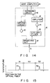
- An arrangement of distribution type temperature sensor processing unit 6 connected to the optical fiber 5 may be the same as ordinary one, and is normally formed as shown in Fig. 14. More specifically, the processing unit 6 emits a laser pulse light as an incident light to the optical fiber 5, isolates a Raman backscattering light to be returned from the optical fiber, photodetects the Raman backscattering light, amplifies and averages the same light. As shown in Fig.
- the processing unit comprises a laser light source 10 for oscillating a laser light pulse as an incident light to the optical fiber, a driving circuit 11 for driving the laser light source 10, a branching unit 12 for separating a Raman backscattering light from reflected scattering light to be returned from the optical fiber 5, a cut-off filter 13 for cutting off the light component except the Raman light in the Raman backscattering light, a photodetector 14 for converting the Raman backscattering light to be output from the cut-off filter 13 into an electric signal, an amplifier 15 for amplifying the electric signal from the photodetector 14, and an averaging circuit 16 for improving S/N ratio of the electric signal.
- the output signal from the processing unit 6 (the output signal from the averaging circuit 16) is applied to the host computer 9, and a control signal from the host computer 9 is applied to the processing unit 6.
- the host computer 9 calculates the output signal from the processing unit 6 to obtain a temperature distribution in the longitudinal direction of the optical fiber 5 and to further obtain the temperature peak position, i.e., the occurrence location of a trouble such as a ground-fault.
- the host computer 9 calculates the data obtained by the signal from the portions of the optical fiber, and can accurately obtain the temperature peak position, i.e., the occurrence location of a trouble such as a ground-fault. For example, if a temperature peak occurs at the joint portion 2A (the boundary area 8A) due to a trouble such as a ground-fault, as shown in Fig. 15, temperature peaks P1 and P2 occur at the two portions 51 and 52 of the optical fiber 5. Accordingly, when the host computer 9 stores in advance the length of the surplus portion 53 and the superposing length of the portions 51 and 52, the computer 9 can obtain the temperature peak position of the joint portion 2A.
- a concrete arrangement in which the optical fiber 5 is laid along the unit cables 3A to 3C and the joint portions 2A and 2B is optional.
- the optical fiber 5 may be supported by suitable supporting means (not shown) linearly along the longitudinal direction of the electric power cable line, or spirally wound on the electric power cable line as shown in Fig. 17.
- suitable supporting means not shown
- the superposition of the two portions of the optical fiber at the joint portions 2A and 2B to be laid along the optical fiber is not limited to the case that the optical fiber is superposed double at the same side of the joint portions 2A and 2B or arranged adjacent to each other.
- it includes that the portions of the optical fiber are arranged on the opposed surfaces of the joint portions 2A and 2B.
- the two portions 51, 52; 54, 55 of the optical fiber 5 are superposed to be laid along the joint portions 2A and 2B (the boundary areas 8A and 8B).
- the embodiment may be varied.
- three or more portions having different longitudinal directions of the optical fiber may be superposed to be laid along the joint portions 2A and 2B (the boundary areas 8A and 8B).
- three portions 51, 52, 57 of the optical fiber 5 may be superposed to be laid along the joint portion 2A (the boundary area 8A).
- a surplus portion is not particularly formed between the portions 51, 52 and 57 of the optical fiber 5.
- the boundaries 7A and 7B are disposed at the centers of the joint portions 2A and 2B.
- the embddiment may be varied.
- the boundaries 7A and 7B may be disposed at the ends of the joint portions 2A and 2B.
- the boundary areas 8A and 8B may be normally determined, similarly to the above-described embodiment, to be the same areas as the joint portions 2A and 2B.
- areas including the portions of both sides of the boundaries 7A and 7B at the ends of the joint portions 2A and 2B, i.e., areas including both the joint portions and the ends of the unit cables connected to the joint portions may be determined to be boundary areas.
- boundaries 7A and 7B may also be set at individually independent positions from the joint portions 2A and 2B.
- the boundary areas 8A and 8B are disposed at the positions isolated from the joint portions 2A and 2B, the embodiment differs from other embodiments.
- the two or more portions of the same optical fibers having different longitudinal directions are superposed to be laid along the areas in the vicinity of the boundary of the electric power cable line. Therefore, the temperature peak position, i.e., the occurrence location of a trouble such as a ground-fault is detected by the two or more portions of the optical fiber in the areas, hence the position can be accurately detected, and thus at which of the adjacent sections the trouble occurs can be easily determined.
- the two or more portions of the same optical fiber having different longitudinal directions are superposed to be laid along the joint portions of the unit cables of the electric power cable line. Therefore, the temperature peak position, i.e., the occurrence location of a trouble such as a ground-fault is detected by the two or more portions of the optical fiber at the joint portions, and hence the trouble occurrence signal of the joint portion having high occurrence frequency of a trouble such as the ground-fault can be accurately detected.
Claims (3)
- Faseroptik-Verlegeanordnung für ein Meßsystem für den Fehlerauftrittsort einer elektrischen Starkstromkabelleitung zur Erfassung eines Fehlerauftrittsortes durch Verlegen einer Faseroptik (5a bis 5d) eines Temperaturdetektors eines Raman-Rückstreuungs-Faseroptik-Temperaturverteilungssensors entlang einer elektrischen Starkstromkabelleitung (1) und Erfassung einer Temperaturanstiegsposition der Starkstromkabelleitung, dadurch gekennzeichnet, daß
unabhängige Faseroptiken entlang der elektrischen Starkstromkabelleitung verlegt werden, und ein Abschnitt einer der Faseroptiken überlagert auf einem Abschnitt einer benachbarten Faseroptik verlegt wird. - Faseroptikverlegeanordnung nach Anspruch 1, dadurch gekennzeichnet, daß:
die elektrische Starkstromkabelleitung (1) in mehrere Abschnitte (4A bis 4D) unterteilt ist,
die unabhängigen Faseroptiken in den jeweiligen Abschnitten angeordnet sind, und
der Abschnitt der einen Faseroptik und der Abschnitt der benachbarten Faseroptik in der Nähe einer Grenze der benachbarten Abschnitte liegen. - Faseroptik-Verlegeanordnung nach Anspruch 1, dadurch gekennzeichnet, daß:
die elektrische Starkstromkabelleitung (1) mehrere Einheitskabel (3A bis 3D) aufweist, die in Reihe geschaltet sind,
die unabhängigen Faseroptiken entlang den Einheitskabeln verlegt sind, und
der Abschnitt der einen Faseroptik und der Abschnitt der benachbarten Faseroptik sich in einem Verbindungsabschnitt (2A bis 2C) der benachbarten Einheitskabel befinden.
Priority Applications (1)
| Application Number | Priority Date | Filing Date | Title |
|---|---|---|---|
| EP95109611A EP0677748A1 (de) | 1990-07-11 | 1991-07-11 | System zur Lokalisierung von Fehlerstellen in einem elektrischen Leistungskabel mit Hilfe einer Anordnung zum Verlegen von optischen Fasern |
Applications Claiming Priority (6)
| Application Number | Priority Date | Filing Date | Title |
|---|---|---|---|
| JP183078/90 | 1990-07-11 | ||
| JP18307890A JP2581607B2 (ja) | 1990-07-11 | 1990-07-11 | 電力ケーブル線路事故点検出システムにおける検出用光ファイバ布設構造 |
| JP2185969A JPH0748073B2 (ja) | 1990-07-13 | 1990-07-13 | 電力ケーブル線路事故点検出システムにおける検出用光ファイバ布設構造 |
| JP185969/90 | 1990-07-13 | ||
| JP2192444A JPH071296B2 (ja) | 1990-07-20 | 1990-07-20 | 電力ケーブル線路事故点検出システムにおける検出用光ファイバ布設構造 |
| JP192444/90 | 1990-07-20 |
Related Child Applications (1)
| Application Number | Title | Priority Date | Filing Date |
|---|---|---|---|
| EP95109611.4 Division-Into | 1995-06-21 |
Publications (3)
| Publication Number | Publication Date |
|---|---|
| EP0466155A2 EP0466155A2 (de) | 1992-01-15 |
| EP0466155A3 EP0466155A3 (en) | 1992-08-05 |
| EP0466155B1 true EP0466155B1 (de) | 1995-12-27 |
Family
ID=27325248
Family Applications (2)
| Application Number | Title | Priority Date | Filing Date |
|---|---|---|---|
| EP95109611A Withdrawn EP0677748A1 (de) | 1990-07-11 | 1991-07-11 | System zur Lokalisierung von Fehlerstellen in einem elektrischen Leistungskabel mit Hilfe einer Anordnung zum Verlegen von optischen Fasern |
| EP91111563A Revoked EP0466155B1 (de) | 1990-07-11 | 1991-07-11 | System zur Lokalisierung von Fehlerstellen in einem elektrischen Leistungskabel mit Hilfe einer Anordnung zum Verlegen von optischen Fasern |
Family Applications Before (1)
| Application Number | Title | Priority Date | Filing Date |
|---|---|---|---|
| EP95109611A Withdrawn EP0677748A1 (de) | 1990-07-11 | 1991-07-11 | System zur Lokalisierung von Fehlerstellen in einem elektrischen Leistungskabel mit Hilfe einer Anordnung zum Verlegen von optischen Fasern |
Country Status (6)
| Country | Link |
|---|---|
| US (1) | US5178465A (de) |
| EP (2) | EP0677748A1 (de) |
| KR (1) | KR960003646B1 (de) |
| CA (1) | CA2046680C (de) |
| DE (1) | DE69115773T2 (de) |
| MY (1) | MY107621A (de) |
Families Citing this family (33)
| Publication number | Priority date | Publication date | Assignee | Title |
|---|---|---|---|---|
| CA2089223C (en) * | 1992-02-13 | 1999-06-01 | Kazuo Amano | Temperature abnormality detecting structure for fluid pipe |
| US5356220A (en) * | 1992-05-29 | 1994-10-18 | Kawasaki Steel Corporation | Method and apparatus for monitoring temperature of blast furnace and temperature control system using temperature monitoring apparatus |
| FR2719125B1 (fr) * | 1994-04-21 | 1996-05-31 | Gec Alsthom T & D Sa | Dispositif de détection d'arc interne pour câble à haute tension à isolation gazeuse. |
| DE59701018D1 (de) | 1996-02-28 | 2000-02-24 | Siemens Ag | Anordnung zur Fehlerortung bei einem gekapselten Rohrleiter und Fehlerortungsverfahren hierzu |
| JPH10117424A (ja) * | 1996-08-23 | 1998-05-06 | Sumitomo Electric Ind Ltd | 電力ケーブルの埋設深度測定方法 |
| US6167525A (en) * | 1997-02-26 | 2000-12-26 | Pirelli Cavi E Sistemi S.P.A. | Method and system for analysis of electric power transmission link status |
| ATE381803T1 (de) * | 1997-02-26 | 2008-01-15 | Prysmian Cavi Sistemi Energia | Verfahren und vorrichtung zur übertragung von elektrischer leistung über eine verbindung |
| US6281489B1 (en) | 1997-05-02 | 2001-08-28 | Baker Hughes Incorporated | Monitoring of downhole parameters and tools utilizing fiber optics |
| AU7275398A (en) * | 1997-05-02 | 1998-11-27 | Baker Hughes Incorporated | Monitoring of downhole parameters and tools utilizing fiber optics |
| GB9805019D0 (en) * | 1998-03-11 | 1998-05-06 | Bicc Plc | Method of and apparatus for detecting cable oversheath faults and installations in which they are used |
| IL133736A (en) * | 1999-01-22 | 2003-10-31 | Inventio Ag | Synthetic fibre cable |
| DE10111640A1 (de) * | 2001-03-10 | 2002-10-02 | Airbus Gmbh | Verfahren zur Ermittlung und Meldung von Überhitzungen und Feuern in einem Flugzeug |
| KR100426978B1 (ko) * | 2001-12-01 | 2004-04-14 | 엘지전선 주식회사 | 분포 온도 측정 장치의 온도 데이터 보정용 집합 센서 |
| US6811307B2 (en) * | 2002-07-10 | 2004-11-02 | Kenneth J. Crowe | DTS measurement of HV cable temperature profile |
| US6949933B2 (en) * | 2004-02-25 | 2005-09-27 | The Boeing Company | Apparatus and method for monitoring electrical cable chafing via optical waveguides |
| WO2007111389A1 (en) * | 2006-03-24 | 2007-10-04 | Korea Electrotechnology Research Institute | Power cable capable of detecting failure |
| WO2008070766A2 (en) * | 2006-12-07 | 2008-06-12 | University Of Florida Research Foundation, Inc. | Fiber optic fault detection system and method for underground power lines |
| CN102365536B (zh) * | 2009-05-01 | 2014-06-11 | 富士通株式会社 | 温度测定系统以及温度测定方法 |
| KR101088866B1 (ko) * | 2010-09-13 | 2011-12-06 | 한국전력공사 | 광복합 지중 배전케이블 감시 장치 및 그 방법 |
| CN102042885B (zh) * | 2010-10-08 | 2012-05-23 | 电子科技大学 | 一种输电线路塔线体系状态监测装置 |
| US9008992B2 (en) | 2011-03-25 | 2015-04-14 | Thomas & Betts International, Inc. | Testing and monitoring an electrical system |
| WO2013030969A1 (ja) * | 2011-08-31 | 2013-03-07 | 富士通株式会社 | 温度分布測定システム、温度分布測定装置及び温度分布測定方法 |
| CN102788645B (zh) * | 2012-07-18 | 2014-08-20 | 西安交通大学 | 电力设备电连接点温升红外监测系统及监测方法 |
| EP2725398B1 (de) * | 2012-10-23 | 2019-03-20 | Nexans | Elektrische Leitung für ein Kraftfahrzeug |
| GB201505082D0 (en) * | 2015-03-25 | 2015-05-06 | Optasense Holdings Ltd | Detecting failure locations in power cables |
| DE102015109493A1 (de) | 2015-04-07 | 2016-10-13 | Lios Technology Gmbh | Verfahren und Vorrichtung für die Überwachung eines Seekabels |
| GB201601060D0 (en) * | 2016-01-20 | 2016-03-02 | Fotech Solutions Ltd | Distributed optical fibre sensors |
| CN106289572A (zh) * | 2016-11-03 | 2017-01-04 | 南京派光信息技术有限公司 | 基于分布式光纤温度测量的供电牵引电缆异常温升监控方法与系统 |
| CN112578220B (zh) * | 2020-11-26 | 2022-10-28 | 贵州电网有限责任公司 | 一种地下电缆故障在线定位系统及方法 |
| CN112557948A (zh) * | 2020-11-27 | 2021-03-26 | 广东电网有限责任公司肇庆供电局 | 基于故障多特征量提取的配电网单相接地故障识别方法 |
| CN112636474B (zh) * | 2020-12-16 | 2022-06-21 | 湖南小快智造电子科技有限公司 | 一种智慧式用电监管方法 |
| CN113804762B (zh) * | 2021-09-01 | 2023-11-21 | 国网内蒙古东部电力有限公司兴安供电公司 | 基于多光谱三合一图像的设备故障检测方法及系统 |
| CN114061770B (zh) * | 2021-11-25 | 2022-11-04 | 江苏攸米智能科技有限公司 | 一种分布式预制光纤母线测温系统 |
Citations (1)
| Publication number | Priority date | Publication date | Assignee | Title |
|---|---|---|---|---|
| DE3518909A1 (de) * | 1985-05-25 | 1986-11-27 | Felten & Guilleaume Energie | Starkstromkabel, insbesondere fuer spannungen von 6 bis 60 kv, mit eingelegten lichtwellenleitern |
Family Cites Families (11)
| Publication number | Priority date | Publication date | Assignee | Title |
|---|---|---|---|---|
| US4298794A (en) * | 1979-08-30 | 1981-11-03 | United Technologies Corporation | Fiber optic hot spot detector |
| US4432599A (en) * | 1981-03-27 | 1984-02-21 | Sperry Corporation | Fiber optic differential sensor |
| JPS5856041A (ja) * | 1981-09-30 | 1983-04-02 | Fujitsu Ltd | 伝送路障害位置検出方式 |
| JPS59131177A (ja) * | 1983-01-17 | 1984-07-27 | Mitsubishi Electric Corp | 送電線故障位置検出装置 |
| GB2140554A (en) * | 1983-05-26 | 1984-11-28 | Plessey Co Plc | Temperature measuring arrangement |
| JPS60207078A (ja) * | 1984-03-30 | 1985-10-18 | Sumitomo Electric Ind Ltd | 単心電力ケ−ブルの事故区間検出方法 |
| JPS613075A (ja) * | 1984-06-18 | 1986-01-09 | Sumitomo Electric Ind Ltd | 送電線用事故区間判別装置 |
| GB2170593B (en) * | 1985-02-01 | 1988-09-14 | Central Electr Generat Board | Temperature measurement |
| GB2170594B (en) * | 1985-02-04 | 1988-04-13 | Central Electr Generat Board | Measuring temperature |
| GB8730061D0 (en) * | 1987-12-23 | 1988-02-03 | Plessey Co Plc | Improvements relating to optical sensing systems |
| JPH0743286B2 (ja) * | 1988-04-19 | 1995-05-15 | 日立電線株式会社 | 光ファイバ式分布形温度センサ |
-
1991
- 1991-07-09 US US07/727,653 patent/US5178465A/en not_active Expired - Lifetime
- 1991-07-10 CA CA002046680A patent/CA2046680C/en not_active Expired - Fee Related
- 1991-07-10 MY MYPI91001241A patent/MY107621A/en unknown
- 1991-07-11 KR KR1019910011826A patent/KR960003646B1/ko not_active IP Right Cessation
- 1991-07-11 EP EP95109611A patent/EP0677748A1/de not_active Withdrawn
- 1991-07-11 EP EP91111563A patent/EP0466155B1/de not_active Revoked
- 1991-07-11 DE DE69115773T patent/DE69115773T2/de not_active Revoked
Patent Citations (1)
| Publication number | Priority date | Publication date | Assignee | Title |
|---|---|---|---|---|
| DE3518909A1 (de) * | 1985-05-25 | 1986-11-27 | Felten & Guilleaume Energie | Starkstromkabel, insbesondere fuer spannungen von 6 bis 60 kv, mit eingelegten lichtwellenleitern |
Non-Patent Citations (2)
| Title |
|---|
| "Electronics and power", Feb.1977, pages 136-140 * |
| "Eureka transfers technology", April 1986, pages 34-35 * |
Also Published As
| Publication number | Publication date |
|---|---|
| US5178465A (en) | 1993-01-12 |
| DE69115773T2 (de) | 1996-06-05 |
| EP0466155A2 (de) | 1992-01-15 |
| KR960003646B1 (ko) | 1996-03-21 |
| CA2046680A1 (en) | 1992-01-12 |
| MY107621A (en) | 1996-05-15 |
| CA2046680C (en) | 1998-06-30 |
| DE69115773D1 (de) | 1996-02-08 |
| EP0466155A3 (en) | 1992-08-05 |
| EP0677748A1 (de) | 1995-10-18 |
| KR920003063A (ko) | 1992-02-29 |
Similar Documents
| Publication | Publication Date | Title |
|---|---|---|
| EP0466155B1 (de) | System zur Lokalisierung von Fehlerstellen in einem elektrischen Leistungskabel mit Hilfe einer Anordnung zum Verlegen von optischen Fasern | |
| EP0555846B1 (de) | Fluidleitungen mit Anordnung zur Bestimmung abnormaler Temperaturorte | |
| EP0153924B1 (de) | Messvorrichtung und verfahren | |
| CN110497933B (zh) | 基于双波长的安全型列车计轴系统及方法 | |
| US5557400A (en) | Multiplexed sensing using optical coherence reflectrometry | |
| EP1131600A4 (de) | Halbleiterlasersensorvorrichtung | |
| JP3528435B2 (ja) | 路上物体検出装置 | |
| US5739526A (en) | Fibre-optic photoelectric beam device having a transmitting optical unit for detecting a moving object through a control district | |
| CN1025076C (zh) | 电缆线故障位置检测系统的光纤布设结构 | |
| CN1311497A (zh) | 使用模式耦合的光纤侵入检测系统 | |
| JP2581607B2 (ja) | 電力ケーブル線路事故点検出システムにおける検出用光ファイバ布設構造 | |
| JPH0748073B2 (ja) | 電力ケーブル線路事故点検出システムにおける検出用光ファイバ布設構造 | |
| JP2989228B2 (ja) | 電力ケーブル異常点検出装置 | |
| JPH0477682A (ja) | 電力ケーブル線路事故点検出システムにおける検出用光ファイバ布設構造 | |
| JP3423047B2 (ja) | 分布型温度センサおよびこれを用いた電力ケーブルの地絡検知器 | |
| JP2525980B2 (ja) | 光ファイバ式温度分布測定装置 | |
| JPH06221930A (ja) | 分布型温度センサ | |
| JP2577199B2 (ja) | 光ファイバ式分布形温度センサ | |
| JPH07104227B2 (ja) | 端面評定 | |
| JPS60146112A (ja) | 光反射型検出装置 | |
| KR20170023276A (ko) | 다채널 광섬유 온도 검출기가 구비된 수배전반 | |
| KR20240066822A (ko) | Ac/dc 겸용 광전류 센서 | |
| JPH0793054B2 (ja) | 電力ケーブル線路の湿度検知方法 | |
| JPH045529A (ja) | 光ファイバ式温度分布測定装置 | |
| JPH0545403A (ja) | 放電位置検出装置 |
Legal Events
| Date | Code | Title | Description |
|---|---|---|---|
| PUAI | Public reference made under article 153(3) epc to a published international application that has entered the european phase |
Free format text: ORIGINAL CODE: 0009012 |
|
| 17P | Request for examination filed |
Effective date: 19910711 |
|
| AK | Designated contracting states |
Kind code of ref document: A2 Designated state(s): DE FR GB IT |
|
| PUAL | Search report despatched |
Free format text: ORIGINAL CODE: 0009013 |
|
| AK | Designated contracting states |
Kind code of ref document: A3 Designated state(s): DE FR GB IT |
|
| 17Q | First examination report despatched |
Effective date: 19940428 |
|
| GRAA | (expected) grant |
Free format text: ORIGINAL CODE: 0009210 |
|
| AK | Designated contracting states |
Kind code of ref document: B1 Designated state(s): DE FR GB IT |
|
| XX | Miscellaneous (additional remarks) |
Free format text: TEILANMELDUNG 95109611.4 EINGEREICHT AM 11/07/91. |
|
| ITF | It: translation for a ep patent filed |
Owner name: BUGNION S.P.A. |
|
| REF | Corresponds to: |
Ref document number: 69115773 Country of ref document: DE Date of ref document: 19960208 |
|
| ET | Fr: translation filed | ||
| PLBI | Opposition filed |
Free format text: ORIGINAL CODE: 0009260 |
|
| 26 | Opposition filed |
Opponent name: SIEMENS AG Effective date: 19960918 |
|
| PLBF | Reply of patent proprietor to notice(s) of opposition |
Free format text: ORIGINAL CODE: EPIDOS OBSO |
|
| PLBF | Reply of patent proprietor to notice(s) of opposition |
Free format text: ORIGINAL CODE: EPIDOS OBSO |
|
| PLBF | Reply of patent proprietor to notice(s) of opposition |
Free format text: ORIGINAL CODE: EPIDOS OBSO |
|
| PLAW | Interlocutory decision in opposition |
Free format text: ORIGINAL CODE: EPIDOS IDOP |
|
| PLAW | Interlocutory decision in opposition |
Free format text: ORIGINAL CODE: EPIDOS IDOP |
|
| PGFP | Annual fee paid to national office [announced via postgrant information from national office to epo] |
Ref country code: GB Payment date: 19980702 Year of fee payment: 8 |
|
| PGFP | Annual fee paid to national office [announced via postgrant information from national office to epo] |
Ref country code: FR Payment date: 19980708 Year of fee payment: 8 |
|
| PGFP | Annual fee paid to national office [announced via postgrant information from national office to epo] |
Ref country code: DE Payment date: 19980821 Year of fee payment: 8 |
|
| RDAH | Patent revoked |
Free format text: ORIGINAL CODE: EPIDOS REVO |
|
| RDAG | Patent revoked |
Free format text: ORIGINAL CODE: 0009271 |
|
| STAA | Information on the status of an ep patent application or granted ep patent |
Free format text: STATUS: PATENT REVOKED |
|
| 27W | Patent revoked |
Effective date: 19990305 |
|
| GBPR | Gb: patent revoked under art. 102 of the ep convention designating the uk as contracting state |
Free format text: 990305 |