EP0465978A1 - Fils conducteurs électriques pour automobiles - Google Patents
Fils conducteurs électriques pour automobiles Download PDFInfo
- Publication number
- EP0465978A1 EP0465978A1 EP91110875A EP91110875A EP0465978A1 EP 0465978 A1 EP0465978 A1 EP 0465978A1 EP 91110875 A EP91110875 A EP 91110875A EP 91110875 A EP91110875 A EP 91110875A EP 0465978 A1 EP0465978 A1 EP 0465978A1
- Authority
- EP
- European Patent Office
- Prior art keywords
- less
- conductor
- wire
- percent
- copper
- Prior art date
- Legal status (The legal status is an assumption and is not a legal conclusion. Google has not performed a legal analysis and makes no representation as to the accuracy of the status listed.)
- Granted
Links
Images
Classifications
-
- H—ELECTRICITY
- H01—ELECTRIC ELEMENTS
- H01B—CABLES; CONDUCTORS; INSULATORS; SELECTION OF MATERIALS FOR THEIR CONDUCTIVE, INSULATING OR DIELECTRIC PROPERTIES
- H01B1/00—Conductors or conductive bodies characterised by the conductive materials; Selection of materials as conductors
-
- B—PERFORMING OPERATIONS; TRANSPORTING
- B32—LAYERED PRODUCTS
- B32B—LAYERED PRODUCTS, i.e. PRODUCTS BUILT-UP OF STRATA OF FLAT OR NON-FLAT, e.g. CELLULAR OR HONEYCOMB, FORM
- B32B15/00—Layered products comprising a layer of metal
- B32B15/01—Layered products comprising a layer of metal all layers being exclusively metallic
- B32B15/013—Layered products comprising a layer of metal all layers being exclusively metallic one layer being formed of an iron alloy or steel, another layer being formed of a metal other than iron or aluminium
- B32B15/015—Layered products comprising a layer of metal all layers being exclusively metallic one layer being formed of an iron alloy or steel, another layer being formed of a metal other than iron or aluminium the said other metal being copper or nickel or an alloy thereof
-
- H—ELECTRICITY
- H01—ELECTRIC ELEMENTS
- H01B—CABLES; CONDUCTORS; INSULATORS; SELECTION OF MATERIALS FOR THEIR CONDUCTIVE, INSULATING OR DIELECTRIC PROPERTIES
- H01B1/00—Conductors or conductive bodies characterised by the conductive materials; Selection of materials as conductors
- H01B1/02—Conductors or conductive bodies characterised by the conductive materials; Selection of materials as conductors mainly consisting of metals or alloys
Definitions
- This invention relates to a lightweight electric wire conductor for automobiles.
- wires made by twisting wires made of annealed copper (under JIS C 3102) or those plated with tin have heretofore been used.
- the wires are then covered with an insulating material such as vinyl chloride, crosslinked vinyl or crosslinked polyethylene.
- the wires made of aluminum have to have an increased outer diameter or have to consist of an increased number of strands to be twisted together in order to assure a sufficient strength. This will lead to increase in the amount of insulating material used and in the wiring space, which will in turn result in the increased cost and make it more difficult to decrease the weight of the wires.
- the wiring in an automobile requires the use of a great number of terminals. This poses such problems as electrical corrosion at the terminals and deterioration of solderability.
- the wire conductors disclosed in the abovementioned publications show an increased strength due to the addition of tin to copper, which in turn makes it possible to reduce the sectional area of the conductor twisted together. But even with these wires the minimum value of the sectional area is 0.15 - 0.3 mm 2. If lowered to the currently required level of 0.05 - 0.15 mm 2 , the strength will be insufficient. Even if strength is sufficient, the electrical resistance will be too large because the conductivity will be less than 20 percent IACS.
- the conductor wires having a tensile strength of 90 - 140 kgf/mm 2 and a load at break of 6 kgf or more have a satisfactory static strength, they are liable to break when subjected to impact tension during manufacture or mounting on a vehicle.
- the wire conductor according to this invention is made by twisting a plurality of element conductors having the following structure and composition after thermal treatment such as tempering or annealing so that their tensile strength will be 80 - 160 kgf/mm 2 and the elongation at break E be 2 % or more.
- the conductor after twisting has a sectional area D of 0.05 - 0.3 mm 2 , a load at break T of 6 kgf or more and an elongation at break E of 2 % or more.
- the element wires used are composite wires having a conductivity of 25 % IACS or more and having a surface layer made of copper or its alloy and a steel core containing 0.15 - 0.85 % of carbon, one or more of the elements selected from the group consisting of Si, Mn, Ni, Cr, Mo, Nb, V, B, Be, At and Ti in the amount of 0.05 - 0.3 % Si, 0.3 - 1.9 % Mn, 0.5 - 5.0 % Ni, 0.2 - 2.0 % Cr, 0.1 - 1.0 % Mo.
- the composite element wires may be subjected to heat treatment after wire drawing and twisting. Also, they may be drawn after heat treatment or annealing to the extent that the t, T and E values clear required levels.
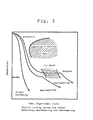
- heat treatment herein used refers to ordinary hardening or tempering or a continuous cooling transformation treatment such as austempering or martempering (Fig. 4).
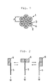
- Fig. 1 shows the section of the wire conductor according to this invention in which the conductor 1 is made by twisting seven strands 2 each having a diameter d.
- numeral 3 designates a steel wire as a core of each strand 2.
- a surface layer 4 is of oxygen-free copper covering the core 3.
- the number of strands used should be 2 - 37, preferably 7 - 19.
- the content of oxygen-free copper or copper alloy put on the outer periphery of the core of the strand should be 20 - 80 percent by weight.
- the conductivity of the strand should not exceed 80 percent IACS.
- the conductivity required 25 percent IACS or more
- good solderability are achieved by the covering.
- the conductor since a steel wire containing 0.20 - 0.75 percent of carbon is used as the core, the conductor has a higher tensile breaking load T, a higher terminal housing retainability and a higher flexibility than conventional conductors. This makes it possible to reduce the sectional area and the weight of the conductor after twisting.
- the tensile strength t of each strand should be within 80 - 160 kg/mm 2 . This is because if less than 80 kg/mm 2 , the load at break of the conductor will be 6 kg or less, if the conductor is made up of seven strands and the total sectional area D is 0.1 mm 2. Such a wire will be more liable to breakage and cannot retain a terminal with a sufficient force. On the other hand, if more than 160 kgf/mm 2 , it is impossible to achieve a 2 % elongation E because the wire is as drawn. Considering the terminal retaining force, the tensile strength t should be preferably 90 - 140 kg/mm 2 .
- the elongation E at break of each strand or the twisted wire should be 2 % or more. If less than 2 %, the wire is liable to breakage due to impact tension during manufacture (when connecting to terminals or covering with vinyl) or when mounted on a car.
- the preferred E value should preferably be 3 % or more.
- the conductivity of each strand should be 25 percent IACS or more. This value was obtained by calculating the permissible current from the electrical resistance of the conductor composed of strands having their surface layer of oxygen-free copper or copper alloy. Supposing that the lowest permissible current is 1 ampere, the conductivity should be 25 percent or more, preferably 30 - 40 percent IACS or more. In order to maintain the required tensile strength by use of the composite material, the conductivity should not exceed 80 percent IACS. If larger than that, the tensile strength will be sacrificed.
- the total sectional area D of the conductor after twisting should be 0.05 - 0.30 mm 2. If more than 0.30 mm 2 , the required strength can be obtained even with a conventional conductor, but it is impossible to achieve decrease in weight. On the other hand, if less than 0.05 mm 2 , the conductor will be liable to deform by tensile force provided the conductor has a T value of 5 kg or less and is composed of seven strands having a diameter of 0.08 mm. More preferably, the D value should be 0.07 - 0.20 mm 2.
- the lower limit of the total sectional area D is 0.5 mm 2 in view of its mechanical properties.
- the lower limit of the D value is ordinarily 0.2 mm 2.
- the strength equivalent to that of a conventional wire having a D value of 0.3 mm 2 can be expected. This will permit a considerable reduction in weight of the conductor (for example, if D is 0.1 mm 2 , the weight will be 60 percent less than the 0.3 mm 2 structure.
- the content of carbon in the steel wire as the core of each strand should be 0.15 - 0.85 percent. If less than 0.15 %, it is difficult to achieve both a tensile strength t of 60 kgf/mm 2 or more and an elongation E of 2 % or more, for any copper content. If more than 0.85 %, the steel wire will be too hard to achieve sufficiently high tensile strength t and elongation E simultaneously and be difficult to thin.
- Si It should be 0.05 % to 0.3 %. If less than 0.05 %, the effect of deoxidation will be insufficient. This leads to increase oxide content in the steel and poor elongation, poor hardening properties and insufficient strength. If more than 0.3 %, the wire will be embrittled so much that the elongation will be lower than 2 %. Also, due to embrittlement, the elongation properties will be poor.
- Mn It should be 0.3 % to 1.9 %. If less than 0.3 %, the effect of deoxidation and hardening property will be insufficient for the same reasons as for Si. Also, the improvement in the corrosion resistance, which is one of the secondary effects, cannot be expected so much. If more than 1.9 %, the elongation will be insufficient and the elongation properties will worsen as in the case of Si.
- Ni It should be 0.5 to 5.0 %. If less than 0.5 %, no improvement in the hardening properties can be expected. The improvement in corrosion resistance will not be expected. If more than 5 %, the hardening properties will not be so high as to justify the increase in cost.
- Be It should be 0.1 to 1.0 %. If less than 0.1 %, the hardening properties will not improve. If more than 1.0 %, the wire will be embrittled.
- Mo It should be 0.1 to 1 %. If less than 0.1 %, the hardening properties will not be good and embrittlement due to tempering cannot be prevented effectively. If more than 1 %, the temperature for the steel to be transformed into austenite (Ms temperature) will rise excessively. This will increase the time for transformation so as not to justify the increased cost as compared with the effect achieved.
- Nb It should be 0.01 % to 0.2 %. If less than 0.01 %, it is difficult to harden the wire by the deposition of carbides or to reduce the crystal grain size. If more than 0.2 % , the wire will be hardened excessively by the deposition of carbides. This will incur cost increase as in case of Mo.
- V It should be 0.01 % to 1.0 %. If not, there will be the same problems as with Nb.
- Ti It should be 0.02 % to 1.0 %. If less than 0.02 %, the effect of improving hardening properties will be insufficient. If more than 1.0 %, the hardening properties will worsen. This may make it difficult to obtain a thin wire by drawing.
- AR It should be 0.02 to 1.0 %. If less than 0.02 %, the effect of deoxidation when dissolved will be insufficient. If more than 1.0 %, oxides such as A1 2 0 3 will develop, causing such trouble as wire breakage during wire drawing.
- P and S These elements should be contained as impurities after dissolution in the amount of 0.05 % or less.
- Cu This element improves corrosion resistance if contained in trace amounts. But if more than 0.3 %, the wire may develop cracks during hot processing or it may crack or be broken during drawing for thinning after heat treatment.
- the weight of the electric wire conductor can be reduced remarkably while keeping the mechanical properties such as terminal housing retaining force, tensile breaking load and flexing resistance, electrical properties and solderability at satisfactory levels. This prevents increases in the weight of wires and space for wiring with increase in the wiring points, thereby reducing the amount of insulating material used and thus the cost.
- OFC tubes tubes made of oxygen-free copper (under JIS 3510) (hereinafter referred to as OFC tubes) were prepared. These covering copper tubes were straight tubes having an external diameter of 16 mm and an internal diameter of 12 mm.
- the steel rods were inserted into the OFC tubes while dry-polishing (shot blast polishing) their surfaces.
- the resulting materials were drawn by a die to reduce the diameter to about 10 mm.
- the copper composite materials thus obtained showed a conductivity of about 30 % for specimen No. 1, about 38 - 40 % for specimens No. 2 - 9 and 11 - 16 and 30 % specimen No. 10.
- specimen Nos. 1, 3 - 8, 10, 13, 14 and 16 were subjected to water quenching starting from 890° C and tempering at 200 C
- specimen No. 2 was subjected to continuous cooling transformation treatment starting from 890 C
- specimen No. 9 was subjected to water quenching from 890 C, tempering at 400 C and light wire drawing.
- Specimen Nos. 11 - 17 were prepared for comparison purposes, of which specimen No. 11 was drawn to a high degree and its elongation at break was less than 2 %.
- No. 12 contained carbon in the amount not within the range defined by the present invention. It was drawn to a high degree and its elongation at break was less than 2 %.
- No. 13 also contained carbon in the amount not within the range defined by the present invention. Its tensile strength was less than 160 kgf/mm 2 even after subjecting it to final heat treatment.
- No. 14 contained carbon in the amount within the range defined in the present invention but the contents of other additives were not within the range defined by the present invention. Thus, its tensile strength was less than 60 kgf/mm 2 .
- the content of carbon was within the range defined by the present invention but those of Si, Mn, Cr, Nb, Ni, At and Mo were not.
- wire breakage happened frequently during wire drawing and while assembling a harness due to the existence of oxides (inclusions) in the core.
- wire conductors having a total sectional area D of 0.08 - 0.1 mm 2. They were then covered with vinyl chloride to a thickness of 0.2 mm for use as electric wires in automobiles.
- the terminal housing retaining force is an important property for high reliability of the connecting portions to terminals. To evaluate this property, after connecting each conductor to a terminal by compressed bonding, it was pulled by a tension tester to measure the load when it comes out of the connecting portion (or when it is broken). Such retaining force should be 7 kg or more, preferably 10 kg or more.
- the tensile breaking load should preferably be about 10 kg or more as far as the elongation of the conductor is 3 % or more.
- the electric wire should have a flexing resistance high enough not to get broken when bent repeatedly near the terminal.
- a jig 6 shown in Fig. 2 was held by a jig 6 shown in Fig. 2 and bent right and left by an angle of 90 degrees in each direction with the load W of 500 g put on one end thereof.
- the flexing resistance was given in terms of the number of reciprocating motions of the wire done without being broken.
- solderability As for the solderability, after immersing the specimens in white rosin flux, they were immersed in eutectic solder kept at 230 C for 2 seconds and the area ratio of the surface wet with molten solder to the entire immersed surface area was measured. A good mark was given for 90 % or more and a bad mark was given for less than 90 %.
- the conductors having a total sectional area of 0.3 mm 2 weigh 4.5 g/m whereas the conductors having a total sectional area of 0.1 mm 2 (specimen Nos. 1 - 4) weigh 1.4 - 1.5 g/m. In other words, the weight reduced by about 3.0 g/m or 70 percent.
- the wires according to the present invention were substantially the same as the conventional wires.
Landscapes
- Non-Insulated Conductors (AREA)
- Conductive Materials (AREA)
Applications Claiming Priority (2)
| Application Number | Priority Date | Filing Date | Title |
|---|---|---|---|
| JP2176083A JPH0465022A (ja) | 1990-07-02 | 1990-07-02 | 自動車用電線導体 |
| JP176083/90 | 1990-07-02 |
Publications (2)
| Publication Number | Publication Date |
|---|---|
| EP0465978A1 true EP0465978A1 (fr) | 1992-01-15 |
| EP0465978B1 EP0465978B1 (fr) | 1996-04-24 |
Family
ID=16007425
Family Applications (1)
| Application Number | Title | Priority Date | Filing Date |
|---|---|---|---|
| EP91110875A Expired - Lifetime EP0465978B1 (fr) | 1990-07-02 | 1991-07-01 | Fils conducteurs électriques pour automobiles |
Country Status (5)
| Country | Link |
|---|---|
| US (1) | US5170015A (fr) |
| EP (1) | EP0465978B1 (fr) |
| JP (1) | JPH0465022A (fr) |
| KR (1) | KR950005852B1 (fr) |
| DE (1) | DE69118976T2 (fr) |
Cited By (5)
| Publication number | Priority date | Publication date | Assignee | Title |
|---|---|---|---|---|
| WO2003092120A2 (fr) * | 2002-04-24 | 2003-11-06 | N.V. Bekaert S.A. | Conducteur electrique a resistance ultra-elevee recouvert de cuivre |
| DE19638372B4 (de) * | 1995-09-20 | 2006-09-28 | Denso Corp., Kariya | Anschlußkabel für einen Sensor |
| EP1337129A3 (fr) * | 2002-02-14 | 2007-05-23 | I.G. Bauerhin GmbH | Elément chauffant électrique destiné au chauffage des sièges et des volants |
| WO2008083785A1 (fr) * | 2006-12-21 | 2008-07-17 | Wabco Gmbh | Dispositif doté d'un capteur et de moyens de couplage |
| CN106205763A (zh) * | 2016-07-14 | 2016-12-07 | 安徽樵森电气科技股份有限公司 | 耐腐蚀防漏电铜芯导线 |
Families Citing this family (15)
| Publication number | Priority date | Publication date | Assignee | Title |
|---|---|---|---|---|
| US6194666B1 (en) * | 1998-03-20 | 2001-02-27 | Chuo Hatsujo Kabushiki Kaisha | Push pull type control cable |
| US6204452B1 (en) * | 1998-05-15 | 2001-03-20 | Servicious Condumex S.A. De C.V. | Flexible automotive electrical conductor of high mechanical strength, and process for the manufacture thereof |
| US6642456B2 (en) * | 1998-05-15 | 2003-11-04 | Servicios Condumex | Flexible automotive electrical conductor of high mechanical strength using a central wire of copper clad steel and the process for manufacture thereof |
| US6239361B1 (en) * | 1999-08-03 | 2001-05-29 | Alvin A. Snaper | Remote replication and translation of a magnetic field |
| US6723451B1 (en) | 2000-07-14 | 2004-04-20 | 3M Innovative Properties Company | Aluminum matrix composite wires, cables, and method |
| US6559385B1 (en) * | 2000-07-14 | 2003-05-06 | 3M Innovative Properties Company | Stranded cable and method of making |
| DE60128468T2 (de) * | 2001-03-01 | 2008-01-17 | Furukawa Electric Co., Ltd., | Stromverteilerbaugruppe |
| JP3719163B2 (ja) * | 2001-05-25 | 2005-11-24 | 日立電線株式会社 | 可動部配線材用撚線導体及びそれを用いたケーブル |
| JP4927366B2 (ja) * | 2005-02-08 | 2012-05-09 | 古河電気工業株式会社 | アルミニウム導電線 |
| JP5306591B2 (ja) * | 2005-12-07 | 2013-10-02 | 古河電気工業株式会社 | 配線用電線導体、配線用電線、及びそれらの製造方法 |
| JP5191144B2 (ja) * | 2007-03-02 | 2013-04-24 | 矢崎総業株式会社 | 素線、電線及び素線の製造方法 |
| WO2010093948A2 (fr) * | 2009-02-12 | 2010-08-19 | Commscope, Inc. Of North Carolina | Marquage antivol pour acier recouvert de cuivre |
| JP6002360B2 (ja) * | 2010-07-21 | 2016-10-05 | 矢崎総業株式会社 | 端子付電線 |
| WO2014202356A1 (fr) * | 2013-06-19 | 2014-12-24 | Nv Bekaert Sa | Fil d'acier revêtu sous forme de fil de blindage pour câble de puissance |
| US11380458B2 (en) * | 2018-08-21 | 2022-07-05 | Sumitomo Electric Industries, Ltd. | Covered electrical wire, terminal-equipped electrical wire, copper alloy wire, and copper alloy stranded wire |
Citations (4)
| Publication number | Priority date | Publication date | Assignee | Title |
|---|---|---|---|---|
| FR899543A (fr) * | 1942-11-28 | 1945-06-04 | Brown | Conducteur électrique en métal plaqué |
| US3404969A (en) * | 1967-10-12 | 1968-10-08 | Gen Cable Corp | Cold-drawn alloy steel wire which can be hot dip coated with aluminum |
| DE2128829A1 (en) * | 1971-06-09 | 1972-12-21 | Olin Corp | Low grain growth metal composites prodn |
| EP0222166A1 (fr) * | 1985-10-11 | 1987-05-20 | Sumitomo Electric Industries Limited | Conducteur électrique à endurance élevée et son procédé de fabrication |
Family Cites Families (5)
| Publication number | Priority date | Publication date | Assignee | Title |
|---|---|---|---|---|
| US2036667A (en) * | 1933-12-20 | 1936-04-07 | Copperweld Steel Co | Bimetallic wire |
| US2134014A (en) * | 1935-05-25 | 1938-10-25 | Copperweld Steel Co | Method and apparatus for rolling bimetallic articles |
| US2317350A (en) * | 1938-11-01 | 1943-04-27 | Nat Standard Co | Copper clad wire and method of preparing the same |
| US2268617A (en) * | 1938-11-01 | 1942-01-06 | Nat Standard Co | Method of making copper clad wire |
| FR1431921A (fr) * | 1964-06-17 | 1966-03-18 | Texas Instruments Inc | élément métallique filiforme et article similaire résistant à la corrosion |
-
1990
- 1990-07-02 JP JP2176083A patent/JPH0465022A/ja active Pending
-
1991
- 1991-07-01 DE DE69118976T patent/DE69118976T2/de not_active Expired - Fee Related
- 1991-07-01 KR KR1019910011088A patent/KR950005852B1/ko not_active IP Right Cessation
- 1991-07-01 EP EP91110875A patent/EP0465978B1/fr not_active Expired - Lifetime
- 1991-07-02 US US07/724,912 patent/US5170015A/en not_active Expired - Fee Related
Patent Citations (4)
| Publication number | Priority date | Publication date | Assignee | Title |
|---|---|---|---|---|
| FR899543A (fr) * | 1942-11-28 | 1945-06-04 | Brown | Conducteur électrique en métal plaqué |
| US3404969A (en) * | 1967-10-12 | 1968-10-08 | Gen Cable Corp | Cold-drawn alloy steel wire which can be hot dip coated with aluminum |
| DE2128829A1 (en) * | 1971-06-09 | 1972-12-21 | Olin Corp | Low grain growth metal composites prodn |
| EP0222166A1 (fr) * | 1985-10-11 | 1987-05-20 | Sumitomo Electric Industries Limited | Conducteur électrique à endurance élevée et son procédé de fabrication |
Cited By (10)
| Publication number | Priority date | Publication date | Assignee | Title |
|---|---|---|---|---|
| DE19638372B4 (de) * | 1995-09-20 | 2006-09-28 | Denso Corp., Kariya | Anschlußkabel für einen Sensor |
| DE19638372B8 (de) * | 1995-09-20 | 2007-01-25 | Denso Corp., Kariya | Anschlußkabel für einen Sensor |
| EP1337129A3 (fr) * | 2002-02-14 | 2007-05-23 | I.G. Bauerhin GmbH | Elément chauffant électrique destiné au chauffage des sièges et des volants |
| WO2003092120A2 (fr) * | 2002-04-24 | 2003-11-06 | N.V. Bekaert S.A. | Conducteur electrique a resistance ultra-elevee recouvert de cuivre |
| WO2003092120A3 (fr) * | 2002-04-24 | 2004-04-01 | Bekaert Sa Nv | Conducteur electrique a resistance ultra-elevee recouvert de cuivre |
| WO2008083785A1 (fr) * | 2006-12-21 | 2008-07-17 | Wabco Gmbh | Dispositif doté d'un capteur et de moyens de couplage |
| CN101542239B (zh) * | 2006-12-21 | 2011-04-20 | 威伯科有限公司 | 具有传感器和联接件的装置 |
| US8006549B2 (en) | 2006-12-21 | 2011-08-30 | Wabco Gmbh | Device comprising a sensor and a connector |
| CN106205763A (zh) * | 2016-07-14 | 2016-12-07 | 安徽樵森电气科技股份有限公司 | 耐腐蚀防漏电铜芯导线 |
| CN106205763B (zh) * | 2016-07-14 | 2017-07-04 | 安徽樵森电气科技股份有限公司 | 耐腐蚀防漏电铜芯导线 |
Also Published As
| Publication number | Publication date |
|---|---|
| EP0465978B1 (fr) | 1996-04-24 |
| KR920003333A (ko) | 1992-02-29 |
| DE69118976T2 (de) | 1996-12-12 |
| JPH0465022A (ja) | 1992-03-02 |
| US5170015A (en) | 1992-12-08 |
| KR950005852B1 (ko) | 1995-05-31 |
| DE69118976D1 (de) | 1996-05-30 |
Similar Documents
| Publication | Publication Date | Title |
|---|---|---|
| EP0465978B1 (fr) | Fils conducteurs électriques pour automobiles | |
| TWI413132B (zh) | 配線用電線導體、配線用電線、以及其等之製造方法 | |
| CN109983141B (zh) | 包覆电线、带端子电线、铜合金线和铜合金绞合线 | |
| US20100294534A1 (en) | Conductor wire for electronic apparatus and electrical wire for wiring using the same | |
| US10453581B2 (en) | Method for manufacturing electric wire | |
| KR20160070089A (ko) | 구리 합금선, 구리 합금 연선, 피복 전선, 와이어 하니스 및 구리 합금선의 제조 방법 | |
| WO2010147018A1 (fr) | Conducteur de fil électrique et fil électrique pour automobile | |
| EP0457186B1 (fr) | Fil conducteur pour faisceau de câblage | |
| US5118906A (en) | Wire conductors for automobiles | |
| EP3576104A1 (fr) | Câble d'isolation | |
| JP7503240B2 (ja) | 被覆電線、端子付き電線、銅合金線、銅合金撚線、及び銅合金線の製造方法 | |
| JP4762701B2 (ja) | 配線用電線導体およびそれを用いた配線用電線 | |
| JP4041970B2 (ja) | 自動車用導体 | |
| EP0957492A2 (fr) | Conducteur électrique flexible pour véhicules automobiles | |
| CN107887053B (zh) | 镀敷铜线、镀敷绞线和绝缘电线以及镀敷铜线的制造方法 | |
| WO2018084263A1 (fr) | Fil électrique revêtu, fil électrique avec borne, fil en alliage de cuivre, et fil toronné en alliage de cuivre | |
| JPH0565571B2 (fr) | ||
| JP7166970B2 (ja) | ワイヤーハーネス用撚り線 | |
| JPH06187831A (ja) | 自動車用電線導体および自動車用電線 | |
| JP3376672B2 (ja) | 耐屈曲性に優れた電気電子機器用導体 | |
| CN113272464A (zh) | 铜合金材料 | |
| JP7054482B2 (ja) | 被覆電線の製造方法、銅合金線の製造方法、及び銅合金撚線の製造方法 | |
| JP7483217B2 (ja) | 被覆電線、端子付き電線、銅合金線、及び銅合金撚線 | |
| JPH06290639A (ja) | 高強度高導電率耐屈曲性複合線 | |
| JPH01189805A (ja) | ワイヤーハーネスのターミナル用銅合金 |
Legal Events
| Date | Code | Title | Description |
|---|---|---|---|
| PUAI | Public reference made under article 153(3) epc to a published international application that has entered the european phase |
Free format text: ORIGINAL CODE: 0009012 |
|
| AK | Designated contracting states |
Kind code of ref document: A1 Designated state(s): DE FR GB SE |
|
| 17P | Request for examination filed |
Effective date: 19911223 |
|
| 17Q | First examination report despatched |
Effective date: 19941129 |
|
| GRAH | Despatch of communication of intention to grant a patent |
Free format text: ORIGINAL CODE: EPIDOS IGRA |
|
| GRAA | (expected) grant |
Free format text: ORIGINAL CODE: 0009210 |
|
| AK | Designated contracting states |
Kind code of ref document: B1 Designated state(s): DE FR GB SE |
|
| REF | Corresponds to: |
Ref document number: 69118976 Country of ref document: DE Date of ref document: 19960530 |
|
| ET | Fr: translation filed | ||
| PLBE | No opposition filed within time limit |
Free format text: ORIGINAL CODE: 0009261 |
|
| STAA | Information on the status of an ep patent application or granted ep patent |
Free format text: STATUS: NO OPPOSITION FILED WITHIN TIME LIMIT |
|
| 26N | No opposition filed | ||
| PGFP | Annual fee paid to national office [announced via postgrant information from national office to epo] |
Ref country code: GB Payment date: 19990630 Year of fee payment: 9 |
|
| PGFP | Annual fee paid to national office [announced via postgrant information from national office to epo] |
Ref country code: DE Payment date: 19990706 Year of fee payment: 9 |
|
| PGFP | Annual fee paid to national office [announced via postgrant information from national office to epo] |
Ref country code: SE Payment date: 19990707 Year of fee payment: 9 |
|
| PGFP | Annual fee paid to national office [announced via postgrant information from national office to epo] |
Ref country code: FR Payment date: 19990709 Year of fee payment: 9 |
|
| PG25 | Lapsed in a contracting state [announced via postgrant information from national office to epo] |
Ref country code: GB Free format text: LAPSE BECAUSE OF NON-PAYMENT OF DUE FEES Effective date: 20000701 |
|
| PG25 | Lapsed in a contracting state [announced via postgrant information from national office to epo] |
Ref country code: SE Free format text: LAPSE BECAUSE OF NON-PAYMENT OF DUE FEES Effective date: 20000702 |
|
| GBPC | Gb: european patent ceased through non-payment of renewal fee |
Effective date: 20000701 |
|
| EUG | Se: european patent has lapsed |
Ref document number: 91110875.1 |
|
| PG25 | Lapsed in a contracting state [announced via postgrant information from national office to epo] |
Ref country code: FR Free format text: LAPSE BECAUSE OF NON-PAYMENT OF DUE FEES Effective date: 20010330 |
|
| REG | Reference to a national code |
Ref country code: FR Ref legal event code: ST |
|
| PG25 | Lapsed in a contracting state [announced via postgrant information from national office to epo] |
Ref country code: DE Free format text: LAPSE BECAUSE OF NON-PAYMENT OF DUE FEES Effective date: 20010501 |