EP0463214A1 - Sende- und Empfangsmodul für eine bidirektionale optische Nachrichten- und Signalübertragung - Google Patents
Sende- und Empfangsmodul für eine bidirektionale optische Nachrichten- und Signalübertragung Download PDFInfo
- Publication number
- EP0463214A1 EP0463214A1 EP90112266A EP90112266A EP0463214A1 EP 0463214 A1 EP0463214 A1 EP 0463214A1 EP 90112266 A EP90112266 A EP 90112266A EP 90112266 A EP90112266 A EP 90112266A EP 0463214 A1 EP0463214 A1 EP 0463214A1
- Authority
- EP
- European Patent Office
- Prior art keywords
- beam splitter
- module according
- encapsulation
- light
- optical fiber
- Prior art date
- Legal status (The legal status is an assumption and is not a legal conclusion. Google has not performed a legal analysis and makes no representation as to the accuracy of the status listed.)
- Granted
Links
- 230000002457 bidirectional effect Effects 0.000 title claims abstract description 8
- 230000008054 signal transmission Effects 0.000 title claims abstract description 4
- 230000003287 optical effect Effects 0.000 title abstract description 9
- 239000013307 optical fiber Substances 0.000 claims abstract description 16
- 230000008878 coupling Effects 0.000 claims abstract description 15
- 238000010168 coupling process Methods 0.000 claims abstract description 15
- 238000005859 coupling reaction Methods 0.000 claims abstract description 15
- 238000005538 encapsulation Methods 0.000 claims abstract description 13
- 238000004519 manufacturing process Methods 0.000 abstract description 4
- 238000004891 communication Methods 0.000 abstract description 3
- 230000001747 exhibiting effect Effects 0.000 abstract 1
- 230000005540 biological transmission Effects 0.000 description 9
- 239000000835 fiber Substances 0.000 description 6
- 230000000903 blocking effect Effects 0.000 description 3
- 239000004065 semiconductor Substances 0.000 description 3
- 238000003466 welding Methods 0.000 description 3
- 238000000926 separation method Methods 0.000 description 2
- 238000004026 adhesive bonding Methods 0.000 description 1
- 238000011161 development Methods 0.000 description 1
- 230000018109 developmental process Effects 0.000 description 1
- 238000005516 engineering process Methods 0.000 description 1
- 230000007613 environmental effect Effects 0.000 description 1
- 238000000605 extraction Methods 0.000 description 1
- 239000011521 glass Substances 0.000 description 1
- 238000000034 method Methods 0.000 description 1
- 239000010453 quartz Substances 0.000 description 1
- 230000035945 sensitivity Effects 0.000 description 1
- VYPSYNLAJGMNEJ-UHFFFAOYSA-N silicon dioxide Inorganic materials O=[Si]=O VYPSYNLAJGMNEJ-UHFFFAOYSA-N 0.000 description 1
- 238000005476 soldering Methods 0.000 description 1
Images
Classifications
-
- G—PHYSICS
- G02—OPTICS
- G02B—OPTICAL ELEMENTS, SYSTEMS OR APPARATUS
- G02B6/00—Light guides; Structural details of arrangements comprising light guides and other optical elements, e.g. couplings
- G02B6/24—Coupling light guides
- G02B6/42—Coupling light guides with opto-electronic elements
- G02B6/4201—Packages, e.g. shape, construction, internal or external details
- G02B6/4246—Bidirectionally operating package structures
Definitions
- the invention relates to a transmitting and receiving module for a bidirectional optical message and signal transmission according to the preamble of claim 1.
- Such a transmission and reception module is known from EP-A-0 238 977.
- two ball lenses are arranged at a distance from one another, essentially between a laser diode and an optical fiber end, which focus the laser light onto the fiber end.
- a light beam separating device or a beam splitter is arranged between the spherical lenses, which separates a light divergently emitted from the fiber end in the direction of the transmitter-distant lens and bundled by this lens with a wavelength different from the wavelength of the laser light and feeds it to a detector or light receiver.
- the laser diode and the lens close to it are fixed relative to one another on a common carrier body so as to prevent misalignment.
- At least the laser diode or the light transmitter, the lens near the transmitter, the light beam separating device (beam splitter) and the light receiver (detector) are accommodated in a housing to which one end of an optical fiber can be connected in such a way that this end is stationary in the housing relative to the common housing Defined focus of the light of a wavelength is arranged.
- the common housing must, however, be hermetically sealed.
- the invention has for its object to simplify the structure of a transmission and reception module of the type mentioned in such a way that the manufacturing effort and thus the manufacturing costs are significantly reduced without neglecting the protection of the active semiconductor components.
- the overall module is formed from subassemblies. These subassemblies are independent components and can be pre-tested or used outside of the overall module as hermetically sealed transmission components and reception components.
- the independent electro-optical transmission and reception components and the beam splitter are arranged in a common housing in such a way that they can receive or send optical signals from or into an optical fiber which is fixedly or detachably connected to the common housing at the same time or in succession.
- the bidirectional module can be used particularly advantageously as an electro-optical transmitting and receiving device for the optical signal or message or data transmission via light-conducting optical fibers such as light guides made of plastic or glass or so-called multimode or single-mode fibers made of quartz for optical communication technology.
- a major advantage of the module according to the invention is that the active semiconductor components (light transmitter and light receiver) are hermetically sealed. As a result, it is no longer necessary to hermetically seal the entire module in a technically complex manner, as is the case with known arrangements. Rather, there are inexpensive options for fiber fastening, both with tight and non-hermetically sealed connection methods (welding, soldering, gluing). In addition, this results in the possibility of releasably coupling the optical fiber with an open plug socket as a connecting part.
- the subassemblies can be adjusted in different orders. It can be carried out, for example, in such a way that the beam splitter and a lens, which may be provided on the fiber connection part, are installed in the common housing before the other elements are installed.
- the adjustment and fixation sequence of the transmitter, receiver and fiber assembly for optimal light extraction and coupling can be done in succession or iteratively together. Fixing the modules can e.g. done by laser welding to the common housing.
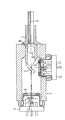
- the bidirectional transmission and reception module shown in the figure essentially consists of a coupling light optic 1, a light receiver 2, a connector 4 for a common optical fiber 6 and a beam splitter 3 interposed in the beam path, which are comprised by a common housing 5, to which the optical fiber 6 can be connected.
- the light transmitter 1, a so-called TO transmitter unit consists, for example, of a base plate 11 with a laser diode 1 mounted thereon and a rear-side monitor diode 12 as well as a lens 7 for focusing the laser beam or as coupling optics.
- the environmentally sensitive monitor laser lens Order is hermetically sealed with an encapsulation, preferably in the form of a window cap 8.
- the transmitter unit can also have only one light-emitting diode (LED) instead of the laser diode 1 and monitor diode 12. In any case, the transmitter unit is an independent component.
- the light receiver 2 or the detector arrangement, a so-called TO receiver unit is mounted on a base plate 14 and is hermetically sealed with an encapsulation, preferably in the form of a flat window cap 9.
- the plan window of the cap 9 can be designed as a blocking filter for a certain light wavelength. However, it can also be transparent for this wavelength and have an additional blocking filter 15 which can be fixed inside or outside the plan window of the cap 9. In certain cases, the blocking filter can also be missing entirely.
- the plan window of the cap 9 or hermetically sealed encapsulation can also be designed as a lens.
- the detector arrangement or the light receiver 2 can expediently be provided with an internal lens 13 as coupling optics. However, the detector arrangement can also be constructed without such a lens and consist of only one photodiode. Another alternative for the detector arrangement is the use of a photodiode with an amplifier unit or an amplifier with an integrated photodiode. In addition, further electrical and electro-optical passive components can be contained in the detector arrangement. In any case, the receiver unit represents an independent, hermetic component.
- the beam splitter 3 forms an optical separating device for different or identical light wavelengths. For different light wavelengths of transmission and reception branches, i.e. If the beam splitter works wavelength-selectively, a separation of greater than 95 percent can be achieved. With the same wavelength, e.g. for the two branches a 50 percent or other separation can be set.
- a lens 10 is provided as a coupling lens, which in this example is designed as a spherical lens and is mounted in a carrier part 16 for the beam splitter 3 within the common housing 5 is.
- This lens 10 can, however, also be omitted if the entire coupling optics is designed accordingly.
- the common optical fiber 6 can be both fixed and detachable (socket) on the module housing 5. Fixing the modules (transmitter and receiver unit) can e.g. done by laser welding to the common housing 5 (module housing).
Landscapes
- Physics & Mathematics (AREA)
- General Physics & Mathematics (AREA)
- Optics & Photonics (AREA)
- Optical Couplings Of Light Guides (AREA)
Abstract
Description
- Die Erfindung betrifft einen Sende- und Empfangsmodul für eine bidirektionale optische Nachrichten- und Signalübertragung nach dem Oberbegriff des Anspruchs 1.
- Ein derartiger Sende- und Empfangsmodul geht aus der EP-A-0 238 977 als bekannt hervor. Bei diesem Sende- und Empfangsmodul für ein bidirektionales optisches Kommunikationsnetz sind im wesentlichen zwischen einer Laserdiode und einem Lichtleitfaserende zwei Kugellinsen im Abstand voneinander angeordnet, die das Laserlicht auf das Faserende fokussieren. Zwischen den Kugellinsen ist eine Lichtstrahltrenneinrichtung bzw. ein Strahlteiler angeordnet, der ein vom Faserende in Richtung der senderfernen Linse divergent abgestrahltes und von dieser Linse gebündeltes Licht mit einer von der Wellenlänge des Laserlichtes verschiedenen Wellenlänge von dem Strahlengang trennt und einem Detektor bzw. Lichtempfänger zuleitet. Um die Dejustageempfindlichkeit eines solchen Moduls zu vermeiden, sind die Laserdiode und die dieser naheliegende Linse auf einem gemeinsamen Trägerkörper relativ zueinander dejustagesicher fixiert. Zumindest die Laserdiode bzw. der Lichtsender, die sendernahe Linse, die Lichtstrahltrenneinrichtung (Strahlteiler) und der Lichtempfänger (Detektor) sind in einem Gehäuse aufgenommen, an das ein Ende einer optischen Faser so anschließbar ist, daß dieses Ende in dem relativ zum gemeinsamen Gehäuse ortsfest definierten Fokus des Lichtes der einen Wellenlänge angeordnet ist. Zum Schutz gegen störende Umwelteinflüsse, insbesondere der im Gehäuse untergebrachten aktiven Halbleiterbauteile (Lichtsender und Lichtempfänger) muß das gemeinsame Gehäuse allerdings hermetisch dicht sein.
- Der Erfindung liegt die Aufgabe zugrunde, bei einem Sende- und Empfangsmodul der eingangs genannten Art den Aufbau so zu vereinfachen, daß der Herstellaufwand und damit die Herstellungskosten wesentlich reduziert werden, ohne dabei den Schutz der aktiven Halbleiterbauteile zu vernachlässigen.
- Diese Aufgabe wird erfindungsgemäß durch einen Sende- und Empfangsmodul mit den Merkmalen des Anspruchs 1 gelöst.
- Vorteilhafte Ausgestaltungen bzw. Weiterbildungen der Erfindung sind Gegenstand zusätzlicher Ansprüche.
- Die mit der Erfindung erzielten Vorteile bestehen insbesondere darin, daß der Gesamtmodul aus Unterbaugruppen gebildet ist. Diese Unterbaugruppen sind für sich eigenständige Bauelemente und können außerhalb des Gesamtmoduls als hermetisch dichte Sendebauelemente und Empfangsbauelemente vorgeprüft oder auch verwendet werden.
- Die eigenständigen elektrooptischen Sende-und Empfangsbauelemente und der Strahlteiler sind so in einem gemeinsamen Gehäuse angeordnet, daß sie gleichzeitig oder hintereinander optische Signale aus einer oder in eine optische Faser, die fest oder lösbar mit dem gemeinsamen Gehäuse verbunden ist, empfangen oder senden können.
- Der bidirektionale Modul ist als elektrooptische Sende- und Empfangseinrichtung für die optische Signal- bzw. Nachrichten- oder Datenübertragung über lichtleitende optische Fasern wie Lichtleiter aus Kunststoff oder Glas oder sogenannte Multimode- oder Monomodefasern aus Quarz für die optische Nachrichtentechnik besonders vorteilhaft verwendbar.
- Ein wesentlicher Vorteil des erfindungsgemäßen Moduls besteht darin, daß die aktiven Halbleiterbauteile (Lichtsender und Lichtempfänger) hermetisch dicht abgekapselt sind. Hierdurch ist es nicht mehr notwendig, den Gesamtmodul technisch aufwendig hermetisch abzudichten, wie das bei bekannten Anordnungen der Fall ist. Es eröffnen sich vielmehr kostengünstige Möglichkeiten der Faserbefestigung, und zwar sowohl mit dichten als auch mit nicht hermetisch dichten Verbindungsverfahren (Schweißen, Löten, Kleben). Außerdem ergibt sich damit die Möglichkeit, die Lichtleitfaser mit einer offenen Steckerbuchse als Anschlußteil lösbar anzukoppeln.
- Die Justage der Subbaugruppen (Sender- und Empfängerbauelement) kann in unterschiedlichen Reihenfolgen durchgeführt werden. Sie kann beispielsweise so erfolgen, daß der Strahlteiler und eine am Faseranschlußteil gegebenenfalls vorgesehene Linse im gemeinsamen Gehäuse eingebaut sind, bevor die übrigen Elemente eingebaut werden.
- Die Justage- und Fixierungsabfolge der Sender-, Empfänger- und Faserbaugruppe zur optimalen Licht-Aus- und Einkopplung kann hintereinander oder auch iterativ gemeinsam erfolgen. Die Fixierung der Baugruppen kann z.B. durch Laserschweißen an das gemeinsame Gehäuse geschehen.
- Anhand eines in der Figur der Zeichnung dargestellten Ausführungsbeispiels wird die Erfindung im folgenden näher erläutert.
- Der in der Figur dargestellte bidirektionale Sende- und Empfangsmodul besteht im wesentlichen aus einem eine Koppeloptik aufweisenden Lichtsender 1, einem Lichtempfänger 2, einem Anschlußteil 4 für eine gemeinsame Lichtleitfaser 6 und einem im Strahlengang zwischengeordneten Strahlteiler 3, die von einem gemeinsamen Gehäuse 5 umfaßt sind, an das die Lichtleitfaser 6 anschließbar ist. Der Lichtsender 1, eine sogenannte TO-Sendeeinheit, besteht z.B. aus einer Grundplatte 11 mit einer darauf angebrachten Laserdiode 1 und rückseitiger Monitordiode 12 sowie Linse 7 zur Bündelung des Laserstrahls bzw. als Koppeloptik. Die umweltempfindliche Monitor-Laser- Linsen-Anordnung ist hermetisch dicht mit einer Einkapselung vorzugsweise in Form einer Planfensterkappe 8 verschlossen. Die Koppeloptik 7 für den Lichtsender 1, die in diesem bevorzugten Beispiel in Gestalt einer Linse innerhalb der Einkapselung 8 angeordnet ist, kann auch außerhalb der Einkapselung 8 angeordnet sein. Es kann auch zweckmäßig sein, daß die Koppeloptik 7 Teil der Einkapselung 8 ist. Das Planfenster der Kappe 8 ist in einem solchen Fall beispielsweise plan- oder bikonkav ausgebildet. Die Sendeeinheit kann auch anstelle der Laserdiode 1 und Monitordiode 12 nur eine Licht emittierende Diode (LED) besitzen. Die Sendeeinheit stellt in jedem Fall ein eigenständiges Bauelement dar. Der Lichtempfänger 2 bzw. die Detektoranordnung, eine sogenannte TO-Empfangseinheit, ist auf einer Grundplatte 14 angebracht und hermetisch dicht mit einer Einkapselung vorzugsweise in Form einer Planfensterkappe 9 verschlossen. Das Planfenster der Kappe 9 kann für eine bestimmte Lichtwellenlänge als Sperrfilter ausgebildet sein. Es kann aber auch für diese Wellenlänge durchlässig sein und ein zusätzliches Sperrfilter 15 besitzen, das innerhalb oder außerhalb des Planfensters der Kappe 9 fixiert sein kann. In bestimmten Fällen kann das Sperrfilter auch ganz fehlen. Schließlich kann das Planfenster der Kappe 9 bzw. hermetisch dichten Einkapselung auch als Linse ausgebildet sein. Die Detektoranordnung bzw. der Lichtempfänger 2 kann zweckmäßig mit einer internen Linse 13 als Koppeloptik versehen sein. Die Detektoranordnung kann aber auch ohne eine solche Linse aufgebaut sein und nur aus einer Photodiode bestehen. Eine weitere Alternative für die Detektoranordnung ist die Verwendung einer Photodiode mit Verstärkereinheit oder ein Verstärker mit integrierter Photodiode. Außerdem können in der Detektoranordnung noch weitere elektrische und elektrooptische passive Bauelemente enthalten sein. Die Empfangseinheit stellt in jedem Fall ein eigenständiges, hermetisches Bauelement dar.
- Der Strahlteiler 3 bildet eine optische Trenneinrichtung für verschiedene oder gleiche Lichtwellenlängen. Für verschiedene Lichtwellenlängen von Sende- und Empfangszweig, d.h. wenn der Strahlteiler wellenlängenselektiv arbeitet, kann eine Trennung von größer als 95 Prozent erreicht werden. Bei gleicher Wellenlänge kann für die beiden Zweige z.B. eine 50-prozentige oder andere Trennung eingestellt werden.
- Zur Ein- oder Auskoppelung des Lichtes aus der gemeinsamen Lichtleitfaser 6 ist in dem in der Figur dargestellten bevorzugten Ausführungsbeispiel als Koppeloptik eine Linse 10 vorgesehen, die in diesem Beispiel als Kugellinse ausgebildet und in einem Trägerteil 16 für den Strahlteiler 3 innerhalb des gemeinsamen Gehäuses 5 angebracht ist. Diese Linse 10 kann bei entsprechender Auslegung der gesamten Koppeloptik allerdings auch wegbleiben.
- Die gemeinsame Lichtleitfaser 6 kann sowohl fest als auch lösbar (Steckerbuchse) am Modulgehäuse 5 fixiert sein. Die Fixierung der Baugruppen (Sende- und Empfängereinheit) kann z.B. durch Laserschweißen an das gemeinsame Gehäuse 5 (Modulgehäuse) geschehen.
Claims (9)
Priority Applications (3)
| Application Number | Priority Date | Filing Date | Title |
|---|---|---|---|
| EP90112266A EP0463214B1 (de) | 1990-06-27 | 1990-06-27 | Sende- und Empfangsmodul für eine bidirektionale optische Nachrichten- und Signalübertragung |
| DE59009661T DE59009661D1 (de) | 1990-06-27 | 1990-06-27 | Sende- und Empfangsmodul für eine bidirektionale optische Nachrichten- und Signalübertragung. |
| US07/721,399 US5127075A (en) | 1990-06-27 | 1991-06-26 | Transmission and reception module for bi-directional optical message and signal transmission |
Applications Claiming Priority (1)
| Application Number | Priority Date | Filing Date | Title |
|---|---|---|---|
| EP90112266A EP0463214B1 (de) | 1990-06-27 | 1990-06-27 | Sende- und Empfangsmodul für eine bidirektionale optische Nachrichten- und Signalübertragung |
Publications (2)
| Publication Number | Publication Date |
|---|---|
| EP0463214A1 true EP0463214A1 (de) | 1992-01-02 |
| EP0463214B1 EP0463214B1 (de) | 1995-09-13 |
Family
ID=8204147
Family Applications (1)
| Application Number | Title | Priority Date | Filing Date |
|---|---|---|---|
| EP90112266A Expired - Lifetime EP0463214B1 (de) | 1990-06-27 | 1990-06-27 | Sende- und Empfangsmodul für eine bidirektionale optische Nachrichten- und Signalübertragung |
Country Status (3)
| Country | Link |
|---|---|
| US (1) | US5127075A (de) |
| EP (1) | EP0463214B1 (de) |
| DE (1) | DE59009661D1 (de) |
Cited By (12)
| Publication number | Priority date | Publication date | Assignee | Title |
|---|---|---|---|---|
| DE4214791C1 (de) * | 1992-05-04 | 1993-07-15 | Ant Nachrichtentechnik Gmbh, 7150 Backnang, De | |
| DE4238203A1 (de) * | 1992-11-09 | 1994-05-11 | Siemens Ag | Kopplungs-Modul |
| EP0644668A1 (de) * | 1993-09-15 | 1995-03-22 | Siemens Aktiengesellschaft | Sende- und Empfangsmodul für eine bidirektionale optische Mehrkanal-Übertragung |
| EP0644669A1 (de) * | 1993-09-15 | 1995-03-22 | Siemens Aktiengesellschaft | Sende- und Empfangsmodul mit temperaturstabilisierter Sendewellenlänge |
| EP0706069A1 (de) | 1994-10-06 | 1996-04-10 | Siemens Aktiengesellschaft | Sende- und Empfangsmodul für eine bidirektionale optische Nachrichten- und Signalübertragung |
| DE19823691A1 (de) * | 1998-05-27 | 1999-12-02 | Siemens Ag | Gehäuseanordnung für Lasermodul |
| DE19952420A1 (de) * | 1999-10-30 | 2001-05-31 | Tsk Pruefsysteme Fuer Elek Sch | Verfahren zur Durchgängigkeitsprüfung für einen Lichtwellenleiter |
| DE19952418A1 (de) * | 1999-10-30 | 2001-06-28 | Tsk Pruefsysteme Fuer Elek Sch | Verfahren zur Prüfung eines Lichtwellenleiters |
| US6493121B1 (en) | 1998-04-30 | 2002-12-10 | Infineon Technologies Ag | Bidirectional module for multichannel use |
| DE19947889C2 (de) * | 1999-10-05 | 2003-03-06 | Infineon Technologies Ag | Optoelektronisches, bidirektionales Sende- und Empfangsmodul in Leadframe-Technik |
| DE10348675B3 (de) * | 2003-10-15 | 2005-06-09 | Infineon Technologies Ag | Modul für eine bidirektionale optische Signalübertragung |
| EP1672402A1 (de) * | 2004-12-15 | 2006-06-21 | Infineon Technologies Fiber Optics GmbH | Sende- und Empfangsmodul für eine bidirektionale optische Datenübertragung |
Families Citing this family (59)
| Publication number | Priority date | Publication date | Assignee | Title |
|---|---|---|---|---|
| SE468150B (sv) * | 1991-05-06 | 1992-11-09 | Asea Brown Boveri | Optoelektronisk komponent |
| DE69210340T2 (de) * | 1991-09-25 | 1997-01-02 | Nippon Electric Co | Optischer Modul |
| JPH0595169A (ja) * | 1991-10-02 | 1993-04-16 | Nec Corp | 半導体レーザ装置および半導体レーザモジユール |
| JP2986613B2 (ja) * | 1992-05-27 | 1999-12-06 | 株式会社日立製作所 | 光伝送モジュール |
| US5285512A (en) * | 1992-06-24 | 1994-02-08 | Litton Systems, Inc. | Fiber optic transceiver with integrated coupler |
| EP0613032B1 (de) * | 1993-02-23 | 1999-01-20 | The Whitaker Corporation | Faseroptische Kopplungseinrichtung |
| US5416870A (en) * | 1993-12-03 | 1995-05-16 | Motorola, Inc. | Optoelectronic interface device and method with reflective surface |
| DE59308228D1 (de) * | 1993-12-22 | 1998-04-09 | Siemens Ag | Sende- und Empfangsmodul für eine bidirektionale optische Nachrichten- und Signalübertragung |
| US5479540A (en) * | 1994-06-30 | 1995-12-26 | The Whitaker Corporation | Passively aligned bi-directional optoelectronic transceiver module assembly |
| US5485538A (en) * | 1994-06-30 | 1996-01-16 | The Whitaker Corporation | Bidirectional wavelength division multiplex transceiver module |
| US5487124A (en) * | 1994-06-30 | 1996-01-23 | The Whitaker Corporation | Bidirectional wavelength division multiplex transceiver module |
| US5652813A (en) * | 1995-03-31 | 1997-07-29 | The Whitaker Corporation | Line bi-directional link |
| US5621573A (en) * | 1995-05-18 | 1997-04-15 | The Whitaker Corporation | Microoptic bidirectional module |
| US5933551A (en) * | 1995-09-29 | 1999-08-03 | The Whitaker Corp. | Bidirectional link submodule with holographic beamsplitter |
| US5838859A (en) * | 1995-12-28 | 1998-11-17 | Lucent Technologies Inc. | Bidirectional optical transceiver assembly |
| US5796899A (en) * | 1995-12-28 | 1998-08-18 | Lucent Technologies Inc. | Bidirectional optical transceiver assembly with reduced crosstalk |
| US5841562A (en) * | 1995-12-28 | 1998-11-24 | Lucent Technologies, Inc. | Bidirectional modular optoelectronic transceiver assembly |
| WO1997032344A1 (en) * | 1996-02-28 | 1997-09-04 | The Whitaker Corporation | Packaging for optoelectronic device |
| US5692083A (en) * | 1996-03-13 | 1997-11-25 | The Whitaker Corporation | In-line unitary optical device mount and package therefor |
| JP3745860B2 (ja) * | 1996-05-28 | 2006-02-15 | 古河電気工業株式会社 | 光半導体素子用パッケージおよびその製法 |
| JPH1010373A (ja) * | 1996-06-21 | 1998-01-16 | Toshiba Corp | レセプタクル型光送受信装置およびその製造方法 |
| JPH10153720A (ja) * | 1996-11-25 | 1998-06-09 | Sony Corp | 光送受信装置 |
| DE19711283A1 (de) * | 1997-03-18 | 1998-10-29 | Siemens Ag | Hermetisch dichtes optisches Sendemodul |
| US6382824B1 (en) * | 1997-06-02 | 2002-05-07 | Fiberstars Incorporated | Fiber optics illuminators and lighting system |
| JP3698393B2 (ja) * | 1998-12-11 | 2005-09-21 | 富士通株式会社 | 光送受信モジュールの構造及びその製法 |
| US6454470B1 (en) | 2000-08-31 | 2002-09-24 | Stratos Lightwave, Inc. | Optoelectronic interconnect module |
| JP4494668B2 (ja) * | 2001-04-27 | 2010-06-30 | 古河電気工業株式会社 | コネクタ |
| DE10196455B4 (de) * | 2001-05-23 | 2006-11-16 | Infineon Technologies Ag | Modul für eine optische Signalübertragung |
| US6954592B2 (en) * | 2002-01-24 | 2005-10-11 | Jds Uniphase Corporation | Systems, methods and apparatus for bi-directional optical transceivers |
| AU2003214962A1 (en) * | 2002-02-01 | 2003-09-02 | Zonu, Inc. | Hybrid optical module employing integration of electronic circuitry with active optical devices |
| US6939058B2 (en) * | 2002-02-12 | 2005-09-06 | Microalign Technologies, Inc. | Optical module for high-speed bidirectional transceiver |
| FR2836559B1 (fr) * | 2002-02-28 | 2004-06-04 | Schneider Electric Ind Sa | Dispositif de couplage optique, sonde optique et dispositif de communication comportant un tel dispositif de couplage |
| US6873760B2 (en) * | 2002-03-19 | 2005-03-29 | Opti Work, Inc. | Integrated optical fiber collimator |
| US7021833B2 (en) * | 2002-03-22 | 2006-04-04 | Ban-Poh Loh | Waveguide based optical coupling of a fiber optic cable and an optoelectronic device |
| JP3896905B2 (ja) * | 2002-06-18 | 2007-03-22 | 住友電気工業株式会社 | 光通信装置 |
| KR100480252B1 (ko) * | 2002-10-10 | 2005-04-07 | 삼성전자주식회사 | 이중 캡 구조의 양방향 광송수신기 모듈 |
| US6969204B2 (en) * | 2002-11-26 | 2005-11-29 | Hymite A/S | Optical package with an integrated lens and optical assemblies incorporating the package |
| US20040184727A1 (en) * | 2003-03-18 | 2004-09-23 | Ying-Moh Liu | Integrated optical fiber collimator |
| US20040184695A1 (en) * | 2003-03-18 | 2004-09-23 | Cheng-Hsi Miao | Optical module |
| US20040184759A1 (en) * | 2003-03-18 | 2004-09-23 | Ying-Moh Liu | Integrated optical fiber collimator |
| JP2004354752A (ja) * | 2003-05-29 | 2004-12-16 | Sumitomo Electric Ind Ltd | 一心双方向光モジュールのジョイントフォルダ |
| US7062171B2 (en) * | 2003-07-15 | 2006-06-13 | Yusuke Ota | Multi-wavelength, bi-directional optical multiplexer |
| JP4433730B2 (ja) * | 2003-09-05 | 2010-03-17 | 住友電気工業株式会社 | 光フィルタ保持部材及び光送受信モジュール |
| US20060013541A1 (en) * | 2004-07-16 | 2006-01-19 | Infineon Technologies Fiber Optics Gmbh | Optoelectronic module |
| US20060056850A1 (en) * | 2004-09-02 | 2006-03-16 | Infineon Technologies North America Corp. | Single width LC bi-directional transceiver |
| KR100734874B1 (ko) * | 2005-07-26 | 2007-07-03 | 한국전자통신연구원 | 양방향성 광모듈 |
| CN2898856Y (zh) * | 2005-08-29 | 2007-05-09 | 昂纳信息技术(深圳)有限公司 | 一体化封装光电组件 |
| US7364374B2 (en) | 2006-09-21 | 2008-04-29 | Truelight Corporation | Bi-directional optical signal transmitting and receiving device |
| US7901144B2 (en) * | 2008-03-14 | 2011-03-08 | Finisar Corporation | Optical interconnect solution |
| JP2010054984A (ja) * | 2008-08-29 | 2010-03-11 | Sumitomo Electric Ind Ltd | 光モジュール及びその製造方法 |
| JP2010091824A (ja) * | 2008-10-08 | 2010-04-22 | Sumitomo Electric Ind Ltd | 光モジュール |
| JP5909838B2 (ja) * | 2012-03-22 | 2016-04-27 | 住友電工デバイス・イノベーション株式会社 | 光モジュール |
| CN102854584A (zh) * | 2012-10-09 | 2013-01-02 | 索尔思光电(成都)有限公司 | 一种单纤双向光收发器 |
| DE102013104964A1 (de) * | 2013-05-14 | 2014-11-20 | Micro-Hybrid Electronic Gmbh | Hermetisch gasdichtes optoelektronisches oder elektrooptisches Bauteil sowie Verfahren zu seiner Herstellung |
| KR102172977B1 (ko) * | 2013-08-16 | 2020-11-02 | 주식회사 포벨 | 파장 가변형 파장 선택성 필터가 내장되는 광수신 모듈 |
| EP3514591B1 (de) * | 2016-10-11 | 2021-12-29 | Huawei Technologies Co., Ltd. | Lichtemissions-/aufnahmeanordnung |
| JP7056247B2 (ja) * | 2018-03-08 | 2022-04-19 | 富士通オプティカルコンポーネンツ株式会社 | 光送受信デバイスおよび光送受信モジュール |
| US10921535B1 (en) * | 2019-12-01 | 2021-02-16 | Ezconn Corporation | Optical sub-assembly and telescopic-shaped core cylinder module thereof |
| JP2022050209A (ja) * | 2020-09-17 | 2022-03-30 | 住友電気工業株式会社 | 光モジュール及び光コネクタケーブル |
Citations (4)
| Publication number | Priority date | Publication date | Assignee | Title |
|---|---|---|---|---|
| US4423922A (en) * | 1978-12-18 | 1984-01-03 | The Boeing Company | Directional coupler for optical communications system |
| GB2162336A (en) * | 1984-07-25 | 1986-01-29 | Magnetic Controls Co | Bidirectional optical fibre coupler |
| EP0250331A1 (de) * | 1986-06-20 | 1987-12-23 | COMPAGNIE DEUTSCH (Société Anonyme) | Endstückkopplungsvorrichtung für eine optische Faser mit opto-elektronischen Komponenten und optischer Kopplung |
| DE3735138A1 (de) * | 1987-10-16 | 1989-05-03 | Siemens Ag | Optisches sende- und/oder empfangsmodul mit wenigstens einem optischen filter |
Family Cites Families (1)
| Publication number | Priority date | Publication date | Assignee | Title |
|---|---|---|---|---|
| US4767171A (en) * | 1986-03-27 | 1988-08-30 | Siemens Aktiengesellschaft | Transmission and reception module for a bidirectional communication network |
-
1990
- 1990-06-27 DE DE59009661T patent/DE59009661D1/de not_active Expired - Fee Related
- 1990-06-27 EP EP90112266A patent/EP0463214B1/de not_active Expired - Lifetime
-
1991
- 1991-06-26 US US07/721,399 patent/US5127075A/en not_active Expired - Lifetime
Patent Citations (4)
| Publication number | Priority date | Publication date | Assignee | Title |
|---|---|---|---|---|
| US4423922A (en) * | 1978-12-18 | 1984-01-03 | The Boeing Company | Directional coupler for optical communications system |
| GB2162336A (en) * | 1984-07-25 | 1986-01-29 | Magnetic Controls Co | Bidirectional optical fibre coupler |
| EP0250331A1 (de) * | 1986-06-20 | 1987-12-23 | COMPAGNIE DEUTSCH (Société Anonyme) | Endstückkopplungsvorrichtung für eine optische Faser mit opto-elektronischen Komponenten und optischer Kopplung |
| DE3735138A1 (de) * | 1987-10-16 | 1989-05-03 | Siemens Ag | Optisches sende- und/oder empfangsmodul mit wenigstens einem optischen filter |
Cited By (17)
| Publication number | Priority date | Publication date | Assignee | Title |
|---|---|---|---|---|
| DE4214791C1 (de) * | 1992-05-04 | 1993-07-15 | Ant Nachrichtentechnik Gmbh, 7150 Backnang, De | |
| DE4238203A1 (de) * | 1992-11-09 | 1994-05-11 | Siemens Ag | Kopplungs-Modul |
| EP0597562A1 (de) * | 1992-11-09 | 1994-05-18 | Siemens Aktiengesellschaft | Kopplungs-Modul |
| EP0644668A1 (de) * | 1993-09-15 | 1995-03-22 | Siemens Aktiengesellschaft | Sende- und Empfangsmodul für eine bidirektionale optische Mehrkanal-Übertragung |
| EP0644669A1 (de) * | 1993-09-15 | 1995-03-22 | Siemens Aktiengesellschaft | Sende- und Empfangsmodul mit temperaturstabilisierter Sendewellenlänge |
| EP0706069A1 (de) | 1994-10-06 | 1996-04-10 | Siemens Aktiengesellschaft | Sende- und Empfangsmodul für eine bidirektionale optische Nachrichten- und Signalübertragung |
| US5552918A (en) * | 1994-10-06 | 1996-09-03 | Siemens Aktiengesellschaft | Transmission and reception module for a bidirectional optical communication and signal transmission |
| US6493121B1 (en) | 1998-04-30 | 2002-12-10 | Infineon Technologies Ag | Bidirectional module for multichannel use |
| US6422766B1 (en) | 1998-05-27 | 2002-07-23 | Siemens Aktiengesellschaft Ag | Housing configuration for a laser module |
| DE19823691A1 (de) * | 1998-05-27 | 1999-12-02 | Siemens Ag | Gehäuseanordnung für Lasermodul |
| DE19947889C2 (de) * | 1999-10-05 | 2003-03-06 | Infineon Technologies Ag | Optoelektronisches, bidirektionales Sende- und Empfangsmodul in Leadframe-Technik |
| US6731882B1 (en) | 1999-10-05 | 2004-05-04 | Infineon Technologies Ag | Leadframe-based optoelectronic bidirectional transmitting and receiving module |
| DE19952420A1 (de) * | 1999-10-30 | 2001-05-31 | Tsk Pruefsysteme Fuer Elek Sch | Verfahren zur Durchgängigkeitsprüfung für einen Lichtwellenleiter |
| DE19952418A1 (de) * | 1999-10-30 | 2001-06-28 | Tsk Pruefsysteme Fuer Elek Sch | Verfahren zur Prüfung eines Lichtwellenleiters |
| DE19952420C2 (de) * | 1999-10-30 | 2002-05-16 | Tsk Pruefsysteme Fuer Elek Sch | Verfahren und Vorrichtung zur Durchgängigkeitsprüfung für einen Lichtwellenleiter |
| DE10348675B3 (de) * | 2003-10-15 | 2005-06-09 | Infineon Technologies Ag | Modul für eine bidirektionale optische Signalübertragung |
| EP1672402A1 (de) * | 2004-12-15 | 2006-06-21 | Infineon Technologies Fiber Optics GmbH | Sende- und Empfangsmodul für eine bidirektionale optische Datenübertragung |
Also Published As
| Publication number | Publication date |
|---|---|
| US5127075A (en) | 1992-06-30 |
| DE59009661D1 (de) | 1995-10-19 |
| EP0463214B1 (de) | 1995-09-13 |
Similar Documents
| Publication | Publication Date | Title |
|---|---|---|
| EP0463214B1 (de) | Sende- und Empfangsmodul für eine bidirektionale optische Nachrichten- und Signalübertragung | |
| DE19947889C2 (de) | Optoelektronisches, bidirektionales Sende- und Empfangsmodul in Leadframe-Technik | |
| DE10105943B4 (de) | Faseroptisches Linsensystem zum Koppeln von Fasern mit oberflächenbefestigten Bauelementen | |
| DE69416016T2 (de) | Faseroptische Kopplungseinrichtung | |
| DE69923894T2 (de) | Optische Baugruppe zum faseroptischen Senden und Empfangen von Daten | |
| DE69022708T2 (de) | Gehäuse für ein Paar von optischen Vorrichtungen. | |
| DE10065034B4 (de) | Faseroptikanschluß und Verfahren zum Benutzen desselben | |
| DE112010004663B4 (de) | Optisches Kommunikationsmodul | |
| DE102012223460B4 (de) | Eine modifizierte Transistor Kontur Gehäuse Baueinheit zur Verwendung in optischen Kommunikationen | |
| DE102008062307B4 (de) | Optoelektronische Komponente basierend auf Premold-Technologie | |
| DE102008063407B4 (de) | Eine optoelektronische oberflächenmontierte Vorrichtung und ein Verfahren zum Bilden einer optoelektronischen oberflächenmontierten Vorrichtung | |
| EP0383138A2 (de) | Vorrichtung für den optischen Direktempfang mehrerer Wellenlängen | |
| EP0600267A1 (de) | Bidirektionaler optischer Sende- und Empfangsmodul | |
| DE19512771A1 (de) | Optische Signalübertragungsvorrichtung | |
| DE102011113212A1 (de) | Optoelektronisches bauelement | |
| DE102005019562A1 (de) | Optisches Sende- und Empfangsmodul | |
| EP2614396A2 (de) | Optische kopplungsvorrichtung, optoelektronisches bauelement und optoelektronischer transceiver | |
| EP0410143A2 (de) | Optelektrische Sende- und Empfangsvorrichtung | |
| EP0105177A1 (de) | Optisches Koppelglied | |
| EP0644668A1 (de) | Sende- und Empfangsmodul für eine bidirektionale optische Mehrkanal-Übertragung | |
| WO2004027482A1 (de) | Anschlussvorrichtung zum lösbaren verbinden wenigstens eines lichtwellenleiters mit wenigstens einem optoelektronischen bauelement sowie verfahren zum montieren einer solchen anschlussvorrichtung | |
| DE4106721A1 (de) | Anordnung zur ankopplung von lichtwellenleiterenden an empfangselemente | |
| DE60204682T2 (de) | Vorrichtung zum anordnen eines photoelektrischen wandlers auf einem elektrischen signalverarbeitungsgerät | |
| DE19635583A1 (de) | Optoelektronisches Sende- und/oder Empfangsmodul | |
| EP0644669A1 (de) | Sende- und Empfangsmodul mit temperaturstabilisierter Sendewellenlänge |
Legal Events
| Date | Code | Title | Description |
|---|---|---|---|
| PUAI | Public reference made under article 153(3) epc to a published international application that has entered the european phase |
Free format text: ORIGINAL CODE: 0009012 |
|
| 17P | Request for examination filed |
Effective date: 19901205 |
|
| AK | Designated contracting states |
Kind code of ref document: A1 Designated state(s): AT BE CH DE DK ES FR GB GR IT LI LU NL SE |
|
| RBV | Designated contracting states (corrected) |
Designated state(s): DE FR GB IT |
|
| 17Q | First examination report despatched |
Effective date: 19940124 |
|
| GRAA | (expected) grant |
Free format text: ORIGINAL CODE: 0009210 |
|
| AK | Designated contracting states |
Kind code of ref document: B1 Designated state(s): DE FR GB IT |
|
| REF | Corresponds to: |
Ref document number: 59009661 Country of ref document: DE Date of ref document: 19951019 |
|
| ITF | It: translation for a ep patent filed | ||
| ET | Fr: translation filed | ||
| GBT | Gb: translation of ep patent filed (gb section 77(6)(a)/1977) |
Effective date: 19951116 |
|
| PLBE | No opposition filed within time limit |
Free format text: ORIGINAL CODE: 0009261 |
|
| STAA | Information on the status of an ep patent application or granted ep patent |
Free format text: STATUS: NO OPPOSITION FILED WITHIN TIME LIMIT |
|
| 26N | No opposition filed | ||
| REG | Reference to a national code |
Ref country code: GB Ref legal event code: IF02 |
|
| PGFP | Annual fee paid to national office [announced via postgrant information from national office to epo] |
Ref country code: DE Payment date: 20050816 Year of fee payment: 16 |
|
| PGFP | Annual fee paid to national office [announced via postgrant information from national office to epo] |
Ref country code: GB Payment date: 20060615 Year of fee payment: 17 |
|
| PGFP | Annual fee paid to national office [announced via postgrant information from national office to epo] |
Ref country code: FR Payment date: 20060619 Year of fee payment: 17 |
|
| PGFP | Annual fee paid to national office [announced via postgrant information from national office to epo] |
Ref country code: IT Payment date: 20060630 Year of fee payment: 17 |
|
| REG | Reference to a national code |
Ref country code: FR Ref legal event code: TP |
|
| PG25 | Lapsed in a contracting state [announced via postgrant information from national office to epo] |
Ref country code: DE Free format text: LAPSE BECAUSE OF NON-PAYMENT OF DUE FEES Effective date: 20070103 |
|
| GBPC | Gb: european patent ceased through non-payment of renewal fee |
Effective date: 20070627 |
|
| REG | Reference to a national code |
Ref country code: FR Ref legal event code: ST Effective date: 20080229 |
|
| PG25 | Lapsed in a contracting state [announced via postgrant information from national office to epo] |
Ref country code: GB Free format text: LAPSE BECAUSE OF NON-PAYMENT OF DUE FEES Effective date: 20070627 |
|
| PG25 | Lapsed in a contracting state [announced via postgrant information from national office to epo] |
Ref country code: FR Free format text: LAPSE BECAUSE OF NON-PAYMENT OF DUE FEES Effective date: 20070702 |
|
| PG25 | Lapsed in a contracting state [announced via postgrant information from national office to epo] |
Ref country code: IT Free format text: LAPSE BECAUSE OF NON-PAYMENT OF DUE FEES Effective date: 20070627 |