EP0462454B1 - Rohrkupplung - Google Patents
Rohrkupplung Download PDFInfo
- Publication number
- EP0462454B1 EP0462454B1 EP91109249A EP91109249A EP0462454B1 EP 0462454 B1 EP0462454 B1 EP 0462454B1 EP 91109249 A EP91109249 A EP 91109249A EP 91109249 A EP91109249 A EP 91109249A EP 0462454 B1 EP0462454 B1 EP 0462454B1
- Authority
- EP
- European Patent Office
- Prior art keywords
- housing
- pipe coupling
- insert
- coupling according
- pipe
- Prior art date
- Legal status (The legal status is an assumption and is not a legal conclusion. Google has not performed a legal analysis and makes no representation as to the accuracy of the status listed.)
- Expired - Lifetime
Links
Images


Classifications
-
- F—MECHANICAL ENGINEERING; LIGHTING; HEATING; WEAPONS; BLASTING
- F16—ENGINEERING ELEMENTS AND UNITS; GENERAL MEASURES FOR PRODUCING AND MAINTAINING EFFECTIVE FUNCTIONING OF MACHINES OR INSTALLATIONS; THERMAL INSULATION IN GENERAL
- F16L—PIPES; JOINTS OR FITTINGS FOR PIPES; SUPPORTS FOR PIPES, CABLES OR PROTECTIVE TUBING; MEANS FOR THERMAL INSULATION IN GENERAL
- F16L21/00—Joints with sleeve or socket
- F16L21/08—Joints with sleeve or socket with additional locking means
-
- F—MECHANICAL ENGINEERING; LIGHTING; HEATING; WEAPONS; BLASTING
- F16—ENGINEERING ELEMENTS AND UNITS; GENERAL MEASURES FOR PRODUCING AND MAINTAINING EFFECTIVE FUNCTIONING OF MACHINES OR INSTALLATIONS; THERMAL INSULATION IN GENERAL
- F16L—PIPES; JOINTS OR FITTINGS FOR PIPES; SUPPORTS FOR PIPES, CABLES OR PROTECTIVE TUBING; MEANS FOR THERMAL INSULATION IN GENERAL
- F16L21/00—Joints with sleeve or socket
- F16L21/002—Sleeves or nipples for pipes of the same diameter; Reduction pieces
- F16L21/005—Sleeves or nipples for pipes of the same diameter; Reduction pieces made of elastic material, e.g. partly or completely surrounded by clamping devices
-
- F—MECHANICAL ENGINEERING; LIGHTING; HEATING; WEAPONS; BLASTING
- F16—ENGINEERING ELEMENTS AND UNITS; GENERAL MEASURES FOR PRODUCING AND MAINTAINING EFFECTIVE FUNCTIONING OF MACHINES OR INSTALLATIONS; THERMAL INSULATION IN GENERAL
- F16L—PIPES; JOINTS OR FITTINGS FOR PIPES; SUPPORTS FOR PIPES, CABLES OR PROTECTIVE TUBING; MEANS FOR THERMAL INSULATION IN GENERAL
- F16L17/00—Joints with packing adapted to sealing by fluid pressure
- F16L17/02—Joints with packing adapted to sealing by fluid pressure with sealing rings arranged between outer surface of pipe and inner surface of sleeve or socket
- F16L17/04—Joints with packing adapted to sealing by fluid pressure with sealing rings arranged between outer surface of pipe and inner surface of sleeve or socket with longitudinally split or divided sleeve
-
- G—PHYSICS
- G02—OPTICS
- G02B—OPTICAL ELEMENTS, SYSTEMS OR APPARATUS
- G02B6/00—Light guides; Structural details of arrangements comprising light guides and other optical elements, e.g. couplings
- G02B6/44—Mechanical structures for providing tensile strength and external protection for fibres, e.g. optical transmission cables
- G02B6/4439—Auxiliary devices
- G02B6/444—Systems or boxes with surplus lengths
- G02B6/4441—Boxes
- G02B6/4442—Cap coupling boxes
- G02B6/4444—Seals
-
- G—PHYSICS
- G02—OPTICS
- G02B—OPTICAL ELEMENTS, SYSTEMS OR APPARATUS
- G02B6/00—Light guides; Structural details of arrangements comprising light guides and other optical elements, e.g. couplings
- G02B6/44—Mechanical structures for providing tensile strength and external protection for fibres, e.g. optical transmission cables
- G02B6/4439—Auxiliary devices
- G02B6/4471—Terminating devices ; Cable clamps
- G02B6/44775—Cable seals e.g. feed-through
Definitions
- the invention relates to a pipe coupling according to the preamble of claim 1.
- the fact that the sealing lips have excessive dimensions in relation to the nominal diameter of the pipes to be connected gives the possibility of pushing the couplings onto the pipes and laying them together, the pipes simply being strung together and the Couplings can then be pushed over the butt joints.
- the circumferential compression of the lip seal by the constrictable housing leads to an increase in the radial thickness of the sleeve, so that the sleeve is not only pressed against the pipe wall by the housing, but also strives to conform to the pipe surface. This results in a sealing capacity that leaves nothing to be desired, even with a rough or irregular pipe surface, and is also retained over the long term.
- the object of the present invention is to design the known pipe coupling in such a way that the narrowing capacity of the housing is used to increase the insensitivity to changes due to dilation, especially when the coupling is depressurized.
- the annular gap remaining in the assembled state of the coupling between the radial end walls of the coupling housing and the pipe wall is closed by a sliding ring that can be compressed in the circumferential direction: thanks to this measure, the wall of the sleeve can be closed in the Root area between the cuff web and sealing lips without stiffening reinforcement, whereby the correspondingly increased flexing ability of the cuff in the root area counteracts the tendency towards deformation of the web mentioned, or vice versa, ensures that the stiffening of the cuff web by the insert does not lead to a relative movement causing abrasion the sealing and sealing surfaces.
- the housing 10 shown in FIG. 1, which is split lengthways, has a cylindrical jacket 11 and inwardly bent walls 12.
- the insert plate bridging the housing gap 13 is designed analogously, so it encloses a space in the housing in which the elastomer sleeve is readily available can be enclosed at their circumference and at the end.
- the further explanations are initially made on the assumption that this is the case;
- the fact that, according to FIG. 1, there is a ring 16 with a slot 17 between the sleeve 15 and the end walls of the housing is referred to later.
- the housing has a closure 21, consisting of tension tabs 22, tension rods 23 and tension screws 24, which engage in threaded holes in one tension rod 23.
- the housing gap 13 is closed by tightening these screws, the insert plate 14 immersing deeper and deeper into the housing and the housing in the manner of a pipe clamp is narrowed.
- the cuff is compressed in the circumferential sense; on the cuff web 20 beads 25 act on the sealing lips, which are also narrowed and brought to a full support on the tube.
- an annular gap 27 remains between the end walls 12 of the housing and the outer wall of the pipes to be coupled.
- annular insert 28 In the cuff there is an annular insert, generally designated 28 (see also FIG. 2), which has the shape of a snap ring with a V-shaped butt joint 29.
- the snap ring In cross section, the snap ring has the shape of a T with a flat base part 30 and an inwardly projecting annular rib 31.
- the insert consists of a material that is flexible in the circumferential direction, e.g. made of a plastic, whereby it is dimensioned such that the base part, due to the ability of the snap ring to recover, fits snugly and essentially over the entire surface of the cuff web, even when the clutch housing is still in the expanded state.
- the annular rib 31 has such a large internal width that the coupling can easily be pushed onto one of the pipes to be coupled and, after the pipes have been laid, can be pushed over the butt joint of the same. After contraction of the housing, however, the annular rib 31 engages in this butt joint and prevents the coupling from moving due to dilatation movements of the pipes.
- the end sections of the insert at 32 including the base part 30 and the annular rib 31, have an enlarged radius of curvature, namely a flattening.
- the inside width of the ring rib illustrated by the double arrow 33 is smaller than the outside diameter of the pipes to be connected. Nevertheless, the coupling can easily be plugged onto the one tube, since the annular rib 31 or the base part 30 yield in the area of the flats 32 and can be pushed back in the radial direction.
- the base part lying practically over the entire surface of the cuff web holds the cuff web 20 in full contact with the cylindrical jacket 11 of the housing 10 even without internal pressure of the medium to be sealed, so that pipes growing into the coupling due to dilation cause the cuff web 20 to be lifted off do not cause of the housing jacket 11, that is to say that the regions of the sleeve which participate in the sealing cannot slide inwards; the marginal edges of the base part 30 do not necessarily have to form stops interacting with the beads 25.
- the two snap rings 16 (they will be referred to later as slide rings in accordance with their more detailed function) must also be taken into account, as they can also be seen - as can be seen in FIG lock from the inside. It is ensured that the slot 17 of the snap rings closes in the final phase of assembly and the snap rings are brought into contact with the outer wall of the pipes to be coupled by upsetting. This creates a sliding fit between the snap rings and the pipe wall, consequently the snap rings can also be referred to as slide rings. Thanks to this measure, the wall of the sleeve can be made relatively thin in the root area, ie in the area connecting the sealing lips 26 to the sleeve web 20, without axial thickening.
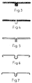
- FIGS. 3-7 can be understood without further explanation, they are intended to indicate the various possibilities and materials that are available with regard to the design of the insert.
Landscapes
- Engineering & Computer Science (AREA)
- General Engineering & Computer Science (AREA)
- Physics & Mathematics (AREA)
- Mechanical Engineering (AREA)
- Fluid Mechanics (AREA)
- General Physics & Mathematics (AREA)
- Optics & Photonics (AREA)
- Quick-Acting Or Multi-Walled Pipe Joints (AREA)
- Joints With Sleeves (AREA)
- Joints Allowing Movement (AREA)
- Packaging Of Annular Or Rod-Shaped Articles, Wearing Apparel, Cassettes, Or The Like (AREA)
- Flanged Joints, Insulating Joints, And Other Joints (AREA)
Applications Claiming Priority (2)
| Application Number | Priority Date | Filing Date | Title |
|---|---|---|---|
| CH2025/90 | 1990-06-18 | ||
| CH202590 | 1990-06-18 |
Publications (2)
| Publication Number | Publication Date |
|---|---|
| EP0462454A1 EP0462454A1 (de) | 1991-12-27 |
| EP0462454B1 true EP0462454B1 (de) | 1993-12-08 |
Family
ID=4224162
Family Applications (1)
| Application Number | Title | Priority Date | Filing Date |
|---|---|---|---|
| EP91109249A Expired - Lifetime EP0462454B1 (de) | 1990-06-18 | 1991-06-06 | Rohrkupplung |
Country Status (9)
| Country | Link |
|---|---|
| US (1) | US5203594A (pt) |
| EP (1) | EP0462454B1 (pt) |
| JP (1) | JPH04231787A (pt) |
| KR (1) | KR940011855B1 (pt) |
| AU (1) | AU627981B2 (pt) |
| BR (1) | BR9102485A (pt) |
| DE (1) | DE59100684D1 (pt) |
| ES (1) | ES2047360T3 (pt) |
| ZA (1) | ZA914664B (pt) |
Families Citing this family (57)
| Publication number | Priority date | Publication date | Assignee | Title |
|---|---|---|---|---|
| US5769467A (en) * | 1995-10-10 | 1998-06-23 | Bridges; Donald Y. | Pipe couplings for misaligned or out-of-round pipes and expanding/contracting pipes |
| IL121796A (en) * | 1997-09-18 | 2001-06-14 | Krausz Metal Ind Ltd | Seal for coupling and connecting means |
| EP0962688B1 (en) | 1998-04-30 | 2006-06-21 | Krausz Metal Industries Ltd. | Universal pipe connectors with a sealing element |
| JP3546250B2 (ja) * | 1999-05-24 | 2004-07-21 | 東拓工業株式会社 | 波形管用継手 |
| FR2798979B1 (fr) * | 1999-09-28 | 2003-09-26 | Daniel Pouillard | Procede et dispositif pour raccordement mecanique etanche |
| DE10006029A1 (de) * | 2000-02-10 | 2001-08-30 | Uwe Vieregge | Anordnung zum Verbinden von zwei Rohren |
| IL153136A (en) * | 2002-11-27 | 2007-06-03 | Eliezer Krausz | Embrace pipe repair |
| US7472911B2 (en) * | 2003-04-25 | 2009-01-06 | Victaulic Company | Gasket for pipe coupling and pipe coupling incorporating same |
| US7086131B2 (en) * | 2004-05-14 | 2006-08-08 | Victaulic Company | Deformable mechanical pipe coupling |
| US7712796B2 (en) | 2004-05-14 | 2010-05-11 | Victaulic Company | Deformable mechanical pipe coupling |
| US7422246B2 (en) * | 2004-08-26 | 2008-09-09 | Straub Tadco Inc. | Remote pipe coupling system |
| DE112006001582B4 (de) * | 2005-06-14 | 2017-12-07 | Parker-Hannifin Corp. | Dichtungsbaueinheit und Fluidkupplung |
| JP4884740B2 (ja) * | 2005-09-27 | 2012-02-29 | コスモ工機株式会社 | 継手部漏水防止装置 |
| IL175107A (en) * | 2006-04-23 | 2010-12-30 | Eliezer Krausz | Seal profile for pipe coupling |
| US7726703B2 (en) * | 2006-06-07 | 2010-06-01 | Victaulic Company | Deformable pipe coupling having multiple radii of curvature |
| US8448995B2 (en) * | 2008-04-17 | 2013-05-28 | Onset Pipe Products, Inc. | Apparatus and method for supporting a pipe coupling |
| US8256800B2 (en) * | 2008-04-17 | 2012-09-04 | Onset Pipe Products, Inc. | Apparatus and method for supporting a pipe coupling |
| US7770941B2 (en) * | 2008-04-17 | 2010-08-10 | Onset Pipe Products Ii, Inc. | Apparatus and method for supporting a pipe coupling |
| US8282136B2 (en) | 2008-06-30 | 2012-10-09 | Mueller International, Llc | Slip on groove coupling with multiple sealing gasket |
| FR2933474B1 (fr) * | 2008-07-03 | 2010-08-27 | Legris Sa | Moyens de connexion renforcee de deux elements de conduite |
| KR100880799B1 (ko) * | 2008-08-25 | 2009-02-02 | 주식회사 도화종합기술공사 | 수밀성이 향상된 관 연결구 |
| US8448993B2 (en) | 2009-06-12 | 2013-05-28 | Romac Industries, Inc. | Pipe coupling |
| US11274777B2 (en) | 2009-06-12 | 2022-03-15 | Romac Industries, Inc. | Pipe coupling |
| US20110095520A1 (en) * | 2009-10-28 | 2011-04-28 | Eliezer Krausz | Pipe coupling with seal pressing device |
| FR2961884B1 (fr) * | 2010-06-23 | 2012-08-10 | Caillau Ets | Collier de serrage a soyage |
| IL209938A (en) * | 2010-12-12 | 2014-06-30 | Eliezer Krausz | Mounting clamp with bushing for clamping element |
| US8864181B2 (en) | 2011-02-16 | 2014-10-21 | Sensus Spectrum, Llc | Split-ring gland pipe coupling with corrugated armor |
| US8528945B2 (en) | 2012-01-30 | 2013-09-10 | Sensus Usa Inc. | Split-ring gland pipe coupling with corrugated armor and annular gasket having pressure assist slot |
| DE102011116768A1 (de) | 2011-10-22 | 2013-04-25 | Norma Germany Gmbh | Profilschelle mit Dichtelement |
| USD696751S1 (en) | 2011-10-27 | 2013-12-31 | Mueller International, Llc | Slip-on gasket |
| USD680630S1 (en) | 2011-11-21 | 2013-04-23 | Mueller International, Llc | Slip-on coupling assembly |
| USD680629S1 (en) | 2011-11-21 | 2013-04-23 | Mueller International, Llc | Slip-on coupling segment |
| US9039046B2 (en) | 2012-01-20 | 2015-05-26 | Mueller International, Llc | Coupling with tongue and groove |
| US9500307B2 (en) | 2012-01-20 | 2016-11-22 | Mueller International, Llc | Slip-on coupling gasket |
| US9534715B2 (en) | 2012-01-20 | 2017-01-03 | Mueller International, Llc | Coupling gasket with multiple sealing surfaces |
| US9194516B2 (en) | 2012-01-20 | 2015-11-24 | Mueller International, Llc | Slip-on coupling |
| US8894100B2 (en) | 2012-03-16 | 2014-11-25 | Romac Industries, Inc. | Fitting with draw mechanism |
| US9168585B2 (en) | 2012-11-02 | 2015-10-27 | Mueller International, Llc | Coupling with extending parting line |
| US10578234B2 (en) * | 2013-05-02 | 2020-03-03 | Victaulic Company | Coupling having arcuate stiffness ribs |
| PL3434955T3 (pl) * | 2013-07-17 | 2021-09-20 | Victaulic Company | Kształtki mające łukowate żebra usztywniające |
| US9791077B2 (en) | 2015-08-17 | 2017-10-17 | Sensus Spectrum Llc | Pipe coupling having double-threaded tightening fastener and associated methods |
| MY196485A (en) | 2015-12-28 | 2023-04-17 | Victaulic Co Of America | Adapter Coupling |
| US10533688B2 (en) | 2016-05-16 | 2020-01-14 | Victaulic Company | Coupling having tabbed retainer |
| US10605394B2 (en) | 2016-05-16 | 2020-03-31 | Victaulic Company | Fitting having tabbed retainer and observation apertures |
| US10859190B2 (en) | 2016-05-16 | 2020-12-08 | Victaulic Company | Sprung coupling |
| US11287076B2 (en) | 2016-12-02 | 2022-03-29 | Total Piping Solutions, Inc. | Encapsulation sleeve gasket assembly with detachable inner layer |
| US11506312B2 (en) | 2016-12-02 | 2022-11-22 | Total Piping Solutions, Inc. | Encapsulation sleeve gasket assembly with detachable inner layer |
| US11506316B2 (en) | 2017-03-06 | 2022-11-22 | Ipex Technologies Inc. | Releasable connect/disconnect fitting connection |
| CA2960023C (en) | 2017-03-06 | 2023-08-08 | Ipex Technologies Inc. | Releasable connect/disconnect fitting connection |
| CA177231S (en) * | 2017-09-25 | 2018-12-20 | Ipex Tech Inc | Quick connect fitting |
| CN107738222B (zh) * | 2017-10-12 | 2019-05-10 | 江苏双楼建设集团有限公司 | 一种薄壁不锈钢环压式连接工具及施工工法 |
| CN107894636B (zh) * | 2017-12-12 | 2019-12-13 | 温岭市泰创塑业有限公司 | 光分路器盒的防水装置 |
| US10871248B2 (en) * | 2018-02-28 | 2020-12-22 | Mueller International, Llc | Coupling gasket with friction-fit range reducer |
| CN108953798A (zh) * | 2018-09-19 | 2018-12-07 | 锋宏泰尼克精密件技术(昆山)有限公司 | 一种带有c形槽的卡箍组件 |
| CN109442108B (zh) * | 2018-12-14 | 2024-05-03 | 山东莱德机械有限公司 | 一种快连卡箍 |
| US11781683B2 (en) | 2019-11-15 | 2023-10-10 | Victaulic Company | Shrouded coupling |
| CA3191928A1 (en) | 2022-03-28 | 2023-09-28 | Tape-Pro Drywall Tools Pty Limited | An improved roller for use in plasterboard finishing |
Family Cites Families (41)
| Publication number | Priority date | Publication date | Assignee | Title |
|---|---|---|---|---|
| CA484214A (en) * | 1952-06-24 | Oliver Beyer Walter | Coupling | |
| US3291506A (en) * | 1966-12-13 | Pipe joints and the oasketing thereof | ||
| CA695250A (en) * | 1964-09-29 | B. Rondum Svend | Stab lock coupling for grooved pipe | |
| DE453908C (de) * | 1924-08-28 | 1927-12-21 | Percy Graham Johnson | Rohrverbindung mit einem hohlen Dichtungsring aus biegsamem Material |
| GB315550A (en) * | 1928-06-19 | 1929-07-18 | Victaulic Company Ltd | Improvements in and relating to pipe joints |
| US2184376A (en) * | 1937-06-10 | 1939-12-26 | Walter O Beyer | Coupling device |
| US2272811A (en) * | 1937-09-14 | 1942-02-10 | Goodrich Co B F | Sealing structure |
| US2295510A (en) * | 1941-05-16 | 1942-09-08 | Chain Belt Co | Flexible pipe section |
| US2398399A (en) * | 1943-02-03 | 1946-04-16 | Millard E Alexander | Pipe joint |
| GB568304A (en) * | 1943-07-30 | 1945-03-28 | John Lubbock | Improvements in and relating to fluid tight joints for pipes and the like |
| US2445151A (en) * | 1944-12-19 | 1948-07-13 | Dresser Ind | Pipe coupling |
| US2635901A (en) * | 1946-12-27 | 1953-04-21 | Alden E Osborn | Joint for smooth-surfaced pipe |
| US2822192A (en) * | 1953-12-07 | 1958-02-04 | Guy M Beatty | Pipe coupling with socketed inflatable sealing member |
| DE1031066B (de) * | 1955-03-24 | 1958-05-29 | Karl Ludwig Lanninger | Schnellkupplung fuer Kunststoffrohre |
| US2971781A (en) * | 1957-02-04 | 1961-02-14 | E B Wiggins Oil Tool Company I | Flexible coupling for beaded end tubing |
| US2939729A (en) * | 1958-04-09 | 1960-06-07 | Preferred Engineering And Res | Quick disconnect coupling |
| US3065005A (en) * | 1959-07-27 | 1962-11-20 | Sr Jesse E Hall | Casing stop collar to mount a well tool |
| US3179445A (en) * | 1961-10-10 | 1965-04-20 | Eternit Spa | Pipe joint spacer member |
| US3250331A (en) * | 1962-10-08 | 1966-05-10 | William G Boyle | Locking device for well tools |
| US3394952A (en) * | 1965-05-03 | 1968-07-30 | Ben B. Garrett | Sewer pipe joint |
| US3572773A (en) * | 1966-09-15 | 1971-03-30 | Owens Illinois Inc | Glass pipe joint |
| US3456963A (en) * | 1967-07-31 | 1969-07-22 | Stephen V Dillon | Bead type coupling for plain end pipe joint |
| US3730502A (en) * | 1969-04-16 | 1973-05-01 | Us Army | Apparatus for vacuum brazing-gas quenching non-ferrous and ferrous alloys |
| US3877733A (en) * | 1973-06-14 | 1975-04-15 | Immanuel Straub | Pipe coupling |
| CH566508A5 (pt) * | 1973-06-15 | 1975-09-15 | Straub Immanuel | |
| US4147738A (en) * | 1977-01-04 | 1979-04-03 | General Electric Company | Process for the solid state polymerization of branched poly(alkylene terephthalates) using aromatic polycarbonates |
| JPS5421618A (en) * | 1977-07-19 | 1979-02-19 | Takenaka Komuten Co Ltd | Pipe coupling using metal rings |
| US4239242A (en) * | 1978-12-18 | 1980-12-16 | Burns William G | Pipe union and seal |
| US4229028A (en) * | 1978-12-20 | 1980-10-21 | Universal Sewer Pipe Company | Pipe coupler |
| US4240654A (en) * | 1979-09-28 | 1980-12-23 | International Harvester Company | Hose end coupling unit |
| US4465330A (en) * | 1980-01-17 | 1984-08-14 | Cenzo Herbert A De | Clam-shell coupling for joining beaded tubes |
| DE3267074D1 (en) * | 1981-01-29 | 1985-12-05 | Mage Ag | Tensible socket for pipes |
| US4426106A (en) * | 1981-07-17 | 1984-01-17 | Mccoy James B | Pipe coupling |
| US4381020A (en) * | 1981-07-30 | 1983-04-26 | Mueller Co. | Single and multiple section pipe repair or service clamps |
| JPS5993589A (ja) * | 1982-11-17 | 1984-05-30 | 倉地 久治 | ホ−ス類の接続装置 |
| DE3570114D1 (en) * | 1984-09-27 | 1989-06-15 | Mage Ag | Tension collar with tension screw |
| DE3445807A1 (de) * | 1984-12-15 | 1986-06-26 | Mage Ag, Courtaman | Spannmuffe fuer rohre |
| CH667904A5 (de) * | 1985-06-17 | 1988-11-15 | Immanuel Straub | Rohrkupplung. |
| CH666949A5 (de) * | 1985-08-09 | 1988-08-31 | Immanuel Straub | Rohrkupplung. |
| US4834398A (en) * | 1987-08-31 | 1989-05-30 | S & B Technical Products, Inc. | Pipe gasket |
| CA1339344E (en) * | 1987-10-07 | 1997-08-26 | Cremco Couplings, A Joint Venture | Soil pipe coupling |
-
1991
- 1991-06-06 DE DE91109249T patent/DE59100684D1/de not_active Expired - Fee Related
- 1991-06-06 ES ES91109249T patent/ES2047360T3/es not_active Expired - Lifetime
- 1991-06-06 EP EP91109249A patent/EP0462454B1/de not_active Expired - Lifetime
- 1991-06-17 KR KR1019910009964A patent/KR940011855B1/ko not_active IP Right Cessation
- 1991-06-17 US US07/716,625 patent/US5203594A/en not_active Expired - Fee Related
- 1991-06-17 BR BR919102485A patent/BR9102485A/pt not_active IP Right Cessation
- 1991-06-18 JP JP3173232A patent/JPH04231787A/ja active Pending
- 1991-06-18 ZA ZA914664A patent/ZA914664B/xx unknown
- 1991-06-18 AU AU79131/91A patent/AU627981B2/en not_active Ceased
Also Published As
| Publication number | Publication date |
|---|---|
| ZA914664B (en) | 1992-03-25 |
| KR940011855B1 (ko) | 1994-12-27 |
| EP0462454A1 (de) | 1991-12-27 |
| ES2047360T3 (es) | 1994-02-16 |
| JPH04231787A (ja) | 1992-08-20 |
| DE59100684D1 (de) | 1994-01-20 |
| AU627981B2 (en) | 1992-09-03 |
| US5203594A (en) | 1993-04-20 |
| AU7913191A (en) | 1991-12-19 |
| KR920001117A (ko) | 1992-01-30 |
| BR9102485A (pt) | 1992-01-21 |
Similar Documents
| Publication | Publication Date | Title |
|---|---|---|
| EP0462454B1 (de) | Rohrkupplung | |
| EP0463424B1 (de) | Rohrkupplung | |
| EP2072877B1 (de) | Vorrichtung zum Verbinden von zwei Rohren mit unterschiedlichen Außendurchmessern | |
| DE8228939U1 (de) | Rohrkupplung | |
| DE3320063C2 (pt) | ||
| EP0551587A1 (de) | Rohrkupplung | |
| DE3339799A1 (de) | Faltenschlauch | |
| EP0551582B1 (de) | Rohrkupplung | |
| DE2621044C3 (de) | Rohrverbindung | |
| DE102009042142A1 (de) | Ringdichtung für ein Schließglied eines Ventils sowie Dichtungsanordnung mit einer solchen Ringdichtung | |
| EP0811778B1 (de) | Zapfenkreuzgarnitur für Kreuzgelenke | |
| WO2001038776A1 (de) | Dichtungseinheit | |
| DE60205816T2 (de) | Flexibler Metallschlauch | |
| EP0780619B1 (de) | Steckstück | |
| DE10019641A1 (de) | Dichtungsanordnung | |
| DE3727871C2 (pt) | ||
| DE1650190B1 (de) | Dichtungsring fuer eine reparaturrohrschelle | |
| DE102011107352A1 (de) | Ringfilter für flüssige oder gasförmige Medien | |
| DE2913365A1 (de) | Rohrkupplung zum verbinden von laengenaenderungen unterworfenen rohren | |
| DE102016105627A1 (de) | Vorrichtung zum Verbinden zweier Rohrelementabschnitte | |
| EP0076275A1 (de) | Abgedichtete und gegen schubkräfte gesicherte muffenverbindung an kunststoffrohren | |
| EP0192597B1 (de) | Muffeninnendichtung für Rohrstösse | |
| EP0066825B1 (de) | Gummimuffe für eine Breitbandschelle | |
| DE2628727A1 (de) | Steckmuffen-verbindung | |
| DE102012005943A1 (de) | Vorrichtung zum Verbinden von zwei Rundkörpern mit unterschiedlichen Außendurchmessern |
Legal Events
| Date | Code | Title | Description |
|---|---|---|---|
| PUAI | Public reference made under article 153(3) epc to a published international application that has entered the european phase |
Free format text: ORIGINAL CODE: 0009012 |
|
| AK | Designated contracting states |
Kind code of ref document: A1 Designated state(s): CH DE ES FR GB IT LI |
|
| 17P | Request for examination filed |
Effective date: 19920306 |
|
| 17Q | First examination report despatched |
Effective date: 19920724 |
|
| GRAA | (expected) grant |
Free format text: ORIGINAL CODE: 0009210 |
|
| AK | Designated contracting states |
Kind code of ref document: B1 Designated state(s): CH DE ES FR GB IT LI |
|
| ET | Fr: translation filed | ||
| GBT | Gb: translation of ep patent filed (gb section 77(6)(a)/1977) |
Effective date: 19931216 |
|
| REF | Corresponds to: |
Ref document number: 59100684 Country of ref document: DE Date of ref document: 19940120 |
|
| ITF | It: translation for a ep patent filed |
Owner name: GUZZI E RAVIZZA S.R.L. |
|
| REG | Reference to a national code |
Ref country code: ES Ref legal event code: FG2A Ref document number: 2047360 Country of ref document: ES Kind code of ref document: T3 |
|
| PLBE | No opposition filed within time limit |
Free format text: ORIGINAL CODE: 0009261 |
|
| STAA | Information on the status of an ep patent application or granted ep patent |
Free format text: STATUS: NO OPPOSITION FILED WITHIN TIME LIMIT |
|
| 26N | No opposition filed | ||
| PGFP | Annual fee paid to national office [announced via postgrant information from national office to epo] |
Ref country code: GB Payment date: 20000512 Year of fee payment: 10 |
|
| PGFP | Annual fee paid to national office [announced via postgrant information from national office to epo] |
Ref country code: DE Payment date: 20000526 Year of fee payment: 10 |
|
| PGFP | Annual fee paid to national office [announced via postgrant information from national office to epo] |
Ref country code: FR Payment date: 20000529 Year of fee payment: 10 |
|
| PGFP | Annual fee paid to national office [announced via postgrant information from national office to epo] |
Ref country code: ES Payment date: 20000622 Year of fee payment: 10 |
|
| PGFP | Annual fee paid to national office [announced via postgrant information from national office to epo] |
Ref country code: CH Payment date: 20000629 Year of fee payment: 10 |
|
| PG25 | Lapsed in a contracting state [announced via postgrant information from national office to epo] |
Ref country code: GB Free format text: LAPSE BECAUSE OF NON-PAYMENT OF DUE FEES Effective date: 20010606 |
|
| PG25 | Lapsed in a contracting state [announced via postgrant information from national office to epo] |
Ref country code: ES Free format text: LAPSE BECAUSE OF NON-PAYMENT OF DUE FEES Effective date: 20010607 |
|
| PG25 | Lapsed in a contracting state [announced via postgrant information from national office to epo] |
Ref country code: LI Free format text: LAPSE BECAUSE OF NON-PAYMENT OF DUE FEES Effective date: 20010630 Ref country code: CH Free format text: LAPSE BECAUSE OF NON-PAYMENT OF DUE FEES Effective date: 20010630 |
|
| GBPC | Gb: european patent ceased through non-payment of renewal fee |
Effective date: 20010606 |
|
| REG | Reference to a national code |
Ref country code: CH Ref legal event code: PL |
|
| PG25 | Lapsed in a contracting state [announced via postgrant information from national office to epo] |
Ref country code: FR Free format text: LAPSE BECAUSE OF NON-PAYMENT OF DUE FEES Effective date: 20020228 |
|
| PG25 | Lapsed in a contracting state [announced via postgrant information from national office to epo] |
Ref country code: DE Free format text: LAPSE BECAUSE OF NON-PAYMENT OF DUE FEES Effective date: 20020403 |
|
| REG | Reference to a national code |
Ref country code: ES Ref legal event code: FD2A Effective date: 20030203 |
|
| PG25 | Lapsed in a contracting state [announced via postgrant information from national office to epo] |
Ref country code: IT Free format text: LAPSE BECAUSE OF NON-PAYMENT OF DUE FEES;WARNING: LAPSES OF ITALIAN PATENTS WITH EFFECTIVE DATE BEFORE 2007 MAY HAVE OCCURRED AT ANY TIME BEFORE 2007. THE CORRECT EFFECTIVE DATE MAY BE DIFFERENT FROM THE ONE RECORDED. Effective date: 20050606 |