EP0461404B1 - Verfahren zur Herstellung einer Küvette für fotometrische oder spektrometrische Messeinrichtungen - Google Patents
Verfahren zur Herstellung einer Küvette für fotometrische oder spektrometrische Messeinrichtungen Download PDFInfo
- Publication number
- EP0461404B1 EP0461404B1 EP91107680A EP91107680A EP0461404B1 EP 0461404 B1 EP0461404 B1 EP 0461404B1 EP 91107680 A EP91107680 A EP 91107680A EP 91107680 A EP91107680 A EP 91107680A EP 0461404 B1 EP0461404 B1 EP 0461404B1
- Authority
- EP
- European Patent Office
- Prior art keywords
- vessel
- soldering
- nanometers
- approximately
- cuvette
- Prior art date
- Legal status (The legal status is an assumption and is not a legal conclusion. Google has not performed a legal analysis and makes no representation as to the accuracy of the status listed.)
- Expired - Lifetime
Links
- 238000000034 method Methods 0.000 title claims description 11
- 238000004519 manufacturing process Methods 0.000 title description 4
- 229910000679 solder Inorganic materials 0.000 claims description 13
- 238000005476 soldering Methods 0.000 claims description 12
- PXHVJJICTQNCMI-UHFFFAOYSA-N Nickel Chemical compound [Ni] PXHVJJICTQNCMI-UHFFFAOYSA-N 0.000 claims description 7
- WUKWITHWXAAZEY-UHFFFAOYSA-L calcium difluoride Chemical compound [F-].[F-].[Ca+2] WUKWITHWXAAZEY-UHFFFAOYSA-L 0.000 claims description 6
- 229910001634 calcium fluoride Inorganic materials 0.000 claims description 6
- 238000005240 physical vapour deposition Methods 0.000 claims description 6
- PCHJSUWPFVWCPO-UHFFFAOYSA-N gold Chemical compound [Au] PCHJSUWPFVWCPO-UHFFFAOYSA-N 0.000 claims description 5
- 239000010931 gold Substances 0.000 claims description 5
- 229910052737 gold Inorganic materials 0.000 claims description 5
- 230000000694 effects Effects 0.000 claims description 4
- 229910052759 nickel Inorganic materials 0.000 claims description 4
- 239000004094 surface-active agent Substances 0.000 claims description 2
- 239000010410 layer Substances 0.000 claims 4
- VYZAMTAEIAYCRO-UHFFFAOYSA-N Chromium Chemical compound [Cr] VYZAMTAEIAYCRO-UHFFFAOYSA-N 0.000 claims 1
- 239000012530 fluid Substances 0.000 claims 1
- 239000011241 protective layer Substances 0.000 claims 1
- 239000007789 gas Substances 0.000 description 10
- 229910052751 metal Inorganic materials 0.000 description 5
- 239000002184 metal Substances 0.000 description 5
- 239000011521 glass Substances 0.000 description 4
- 238000002844 melting Methods 0.000 description 3
- 230000008018 melting Effects 0.000 description 3
- 239000010453 quartz Substances 0.000 description 3
- VYPSYNLAJGMNEJ-UHFFFAOYSA-N silicon dioxide Inorganic materials O=[Si]=O VYPSYNLAJGMNEJ-UHFFFAOYSA-N 0.000 description 3
- 229910001369 Brass Inorganic materials 0.000 description 2
- 238000010521 absorption reaction Methods 0.000 description 2
- 238000000862 absorption spectrum Methods 0.000 description 2
- 239000010951 brass Substances 0.000 description 2
- 239000010436 fluorite Substances 0.000 description 2
- 229930195733 hydrocarbon Natural products 0.000 description 2
- 150000002430 hydrocarbons Chemical class 0.000 description 2
- 239000007788 liquid Substances 0.000 description 2
- 230000007774 longterm Effects 0.000 description 2
- 230000005855 radiation Effects 0.000 description 2
- 229910004261 CaF 2 Inorganic materials 0.000 description 1
- OYPRJOBELJOOCE-UHFFFAOYSA-N Calcium Chemical compound [Ca] OYPRJOBELJOOCE-UHFFFAOYSA-N 0.000 description 1
- 229910045601 alloy Inorganic materials 0.000 description 1
- 239000000956 alloy Substances 0.000 description 1
- OYLGJCQECKOTOL-UHFFFAOYSA-L barium fluoride Chemical compound [F-].[F-].[Ba+2] OYLGJCQECKOTOL-UHFFFAOYSA-L 0.000 description 1
- 229910001632 barium fluoride Inorganic materials 0.000 description 1
- 239000011230 binding agent Substances 0.000 description 1
- 230000015572 biosynthetic process Effects 0.000 description 1
- 239000011575 calcium Substances 0.000 description 1
- 230000003197 catalytic effect Effects 0.000 description 1
- 238000004140 cleaning Methods 0.000 description 1
- 238000002474 experimental method Methods 0.000 description 1
- 238000004868 gas analysis Methods 0.000 description 1
- 230000031700 light absorption Effects 0.000 description 1
- 239000000463 material Substances 0.000 description 1
- 238000005259 measurement Methods 0.000 description 1
- 238000010309 melting process Methods 0.000 description 1
- 238000001465 metallisation Methods 0.000 description 1
- 230000003287 optical effect Effects 0.000 description 1
- 229910052594 sapphire Inorganic materials 0.000 description 1
- 239000010980 sapphire Substances 0.000 description 1
- 238000009210 therapy by ultrasound Methods 0.000 description 1
- 230000007704 transition Effects 0.000 description 1
- 239000012808 vapor phase Substances 0.000 description 1
- 235000012431 wafers Nutrition 0.000 description 1
Images
Classifications
-
- G—PHYSICS
- G01—MEASURING; TESTING
- G01N—INVESTIGATING OR ANALYSING MATERIALS BY DETERMINING THEIR CHEMICAL OR PHYSICAL PROPERTIES
- G01N21/00—Investigating or analysing materials by the use of optical means, i.e. using sub-millimetre waves, infrared, visible or ultraviolet light
- G01N21/01—Arrangements or apparatus for facilitating the optical investigation
- G01N21/03—Cuvette constructions
Definitions
- the invention relates to a method for producing a cuvette for photometric or spectrometric measuring devices.
- cuvettes are required which contain a gas with a defined concentration firmly enclosed in a metal body of defined length, the respective end faces of the cuvette being gas-tight with windows made of calcium fluoride CaF 2 which are permeable to light rays.
- the desired measuring effect results from the defined absorption of light rays by the enclosed gas with a high constancy of the absorption effect.
- a cuvette for optical gas analysis devices is known to connect radiation-permeable windows by means of a glass solder as a hard solder to an intermediate frame.
- the windows prepared in this way are gas-tightly connected to the cuvette housing using a soft solder or a hard solder.
- fluorspar is used as a closing window in cuvettes.
- the absorption spectra of most technically important gases can thus be recorded for measurement purposes.
- This material is also sufficiently unhygroscopic and has no catalytic properties for the filling gases required.
- the invention has for its object to develop a method for producing a non-catalytically active gas-tight cuvette using a solderable connection in the range below 220 ° C between fluorspar and a metal carrier.
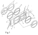
- the embodiment of a cuvette for a photometric measuring device shown in Figure 1 consists of an elongated rectangular container 1 made of metal, for example brass or a suitable brass alloy, in which a gas of defined concentration is enclosed, through which light rays pass.
- the container 1 has semicircular openings, hereinafter referred to as opening 2, which are sealed on both sides 11 and 12 of the container 1 by gas-permeable discs 3 made of calcium fluoride. Between the disks 3 and the edges of the openings 2 there is the gas which is introduced via bores 13 inserted laterally in the container 1.
- 10 solder molded parts are referred to, which are used during the soldering as a binder between the container 1 and the disks 3.
- the function and the long-term constancy of the cuvette described depend crucially on the quality of the connection between the translucent panes and the metal container.
- the procedure described below for preparing and performing the soldering process offers maximum long-term constancy of the gas-filled cuvette.
Landscapes
- Physics & Mathematics (AREA)
- Health & Medical Sciences (AREA)
- Life Sciences & Earth Sciences (AREA)
- Chemical & Material Sciences (AREA)
- Analytical Chemistry (AREA)
- Biochemistry (AREA)
- General Health & Medical Sciences (AREA)
- General Physics & Mathematics (AREA)
- Immunology (AREA)
- Pathology (AREA)
- Optical Measuring Cells (AREA)
- Investigating Or Analysing Materials By Optical Means (AREA)
Description
- Die Erfindung betrifft ein Verfahren zur Herstellung einer Küvette für fotometrische oder spektrometrische Meßeinrichtungen.
Für derartige Meßeinrichtungen werden Küvetten benötigt, die in einem Metallkörper definierter Länge ein Gas mit definierter Konzentration fest eingeschlossen enthalten, wobei die jeweiligen Stirnseiten der Küvette mit für Lichtstrahlen durchlässigen Fenstern aus Kalziumfluorid CaF₂ gasdicht abgeschlossen sind. Der gewünschte Meßeffekt resultiert aus der definierten Absorption von Lichtstrahlen durch das eingeschlossene Gas bei hoher Konstanz des Absorptionseffektes. - Es sind verschiedene Techniken zum Aufbau von Küvetten bekannt. In der Gebrauchsanweisung 42/20-22-0 (9.79) für den Gasanalysator Radas 1G der Fa.Hartmann & Braun ist auf Seite 40 eine Kalibrierküvette beschrieben, die aus Quarz und Übergangsgläsern besteht und in die ein Gas durch Abschmelzen des Glases bei der Schmelztemperatur fest eingeschlossen wird. Ein solches Schmelzverfahren ist jedoch nicht geeignet für Kohlenwasserstoffe und NOx-Gase, die sich bei der hohen Temperatur, wie sie beim Schmelzen von Quarz oder Gläsern benötigt werden, verändern. Andererseits sind Quarz oder Gläser nicht geeignet für Anwendungen im mittleren Infrarot, da die Infrarotstrahlung bereits bei Wellenlängen von ca.4,5 µm bzw. ca.2,5 µm absorbiert wird. Aus dem selben Grund ist auch Saphir nur eingeschränkt verwendbar. Die Absorptionskante liegt hier bei ca.5,5 µm und kann damit die Absorptionsspektren von SO₂ und vieler Kohlenwasserstoffe nicht oder nur teilweise erfassen.
- Aus der DE-OS 30 10 516 ist eine Küvette für optische Gasanalysengeräte bekannt, strahlungsdurchlässige Fenster mittels eines Glaslotes als Hartlot mit einem Zwischenrahmen zu verbinden. Die so vorbereiteten Fenster werden mit einem Weichlot oder einem Hartlot mit dem Küvettengehäuse gasdicht verbunden.
- Aus der DE-OS 27 20 636 ist es bekannt, die strahlungsdurchlässigen Fenster als Scheiben aus Kalzium- oder Bariumfluorid herzustellen.
- Wegen seiner Transparenz für Infrarotstrahlung im mittleren Infrarot bis zu einer Wellenlänge von ca.8 µm wird Flußspat als Abschlußfenster in Küvetten eingesetzt. Damit können die Absorptionsspektren der meisten technisch wichtigen Gase für meßtechnische Zwecke erfaßt werden. Dieses Material ist darüberhinaus ausreichend unhygroskopisch und besitzt keine katalytischen Eigenschaften für die benötigten Füllgase.
- Der Erfindung liegt die Aufgabe zugrunde, ein Verfahren zur Herstellung einer nichtkatalytisch wirkenden gasdichten Küvette unter Einsatz einer im Bereich unter 220°C lötbaren Verbindung zwischen Flußspat und einem Metallträger zu entwickeln.
- Die Lösung der Aufgabe gelingt mit den kennzeichnenden Merkmalen des Patentanspruches. Im folgenden wird das erfindungsgemäße Verfahren anhand eines in den Figuren dargestellten Ausführungsbeispieles einer Küvette näher erläutert. Es zeigen
- Figur 1
- eine Küvette in Explosionsdarstellung und
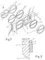
- Figur 2
- den Schnitt durch ein Detail eines beschichteten Fensters in vergrößertem Maßstab.
- Die in Figur 1 dargestellte Ausführungsform einer Küvette für eine fotometrische Meßeinrichtung besteht aus einem länglich rechteckförmigen Behälter 1 aus Metall, beispielsweise Messing oder eine geeignete Messinglegierung, in dem ein Gas definierter Konzentration eingeschlossen ist, durch das Lichtstrahlen hindurchdringen. Zu diesem Zweck besitzt der Behälter 1 halbkreisförmige Durchbrechungen, im folgenden als Öffnung 2 bezeichnet, die auf beiden Seiten 11 und 12 des Behälters 1 mit für Lichtstrahlen durchlässigen Scheiben 3 aus Kalziumfluorid gasdicht verschlossen sind. Zwischen den Scheiben 3 und den Rändern der Öffnungen 2 befindet sich das Gas, welches über seitlich im Behälter 1 eingelassene Bohrungen 13 eingebracht wird. Mit 10 sind Lotformteile bezeichnet, die beim Löten als Bindemittel zwischen dem Behälter 1 und den Scheiben 3 verwendet werden.
- Die Funktion und die Langzeitkonstanz der beschriebenen Küvette hängen entscheidend von der Qualität der Verbindung zwischen den lichtdurchlässigen Scheiben und dem Behälter aus Metall ab. Das im folgenden beschriebene Verfahren zur Vorbereitung und Durchführung des Lötvorganges bietet ein Höchstmaß an Langzeitkonstanz der mit einem Gas gefüllten Küvette.
- Durch Versuche hat sich herausgestellt, daß folgende Verfahrensschritte zur Herstellung der beschriebenen Küvette für deren einwandfreie Funktion unerläßlich sind.
- Reinigen der Scheiben (3) aus Kalziumfluorid durch Ultraschallbehandlung mit speziellen Tensiden.
- Metallisierung der Scheiben (3) an den Rändern (4) im Bereich der Lötfläche (8) mit einem physikalischen Aufdampf-Verfahren (physical vapour deposition oder PVD-Verfahren)
- in folgender Reihenfolge:
- 1. Aufbringen einer Chrom-Nickel-Schicht (5) von ca.50 nanometer,
- 2. Aufbringen einer Nickel-Schicht (6) von ca.200 nanometer und
- 3. Aufbringen einer Gold-Schicht (7) von ca.30 nanometer.
- Ausbildung der Lötfläche (8) mit einem Lotauffangvolumen im unmittelbaren Bereich von der Lötnut (9).
- Aufbringen einer Aktivitätsschutzschicht aus Gold von ca.30 nanometer Dicke auf dem Metallträger (11) im Bereich der Lötfläche (8).
- Verwendung von Lotformteilen (10) mit definierter und genau dosierter Überschußmenge die im Lotauffangvolumen bleibt.
- Löten in der Dampfphase einer Inertflüssigkeit bei verschiedenen Temperaturen für die eine Seite (11) und die andere Seite (12) der Küvette, wobei die Inertflüssigkeit dem Lot der Lotformteile (10) angepaßt ist.
Claims (1)
- Verfahren zur Herstellung einer Küvette für fotometrische Meßeinrichtungen, mit folgenden Merkmalen:- einem von Lichtstrahlen durchdrungenen Behälter (1), in dem ein Gas definierter Konzentration eingeschlossen ist;- der Behälter (1) weist für Lichtstrahlen durchlässige Öffnung (2) auf, die mit Fenstern verschlossen sind;- die Fenster sind als Scheiben (3) aus Kalziumfluorid CaF₂ ausgebildet, die mit dem Behälter (1) gasdicht verbunden sind- und zwischen den Scheiben (3) und dem Behälter (1) eine Lötverbindung besteht,dadurch gekennzeichnet, daß die Lötverbindung nach folgenden Verfahrensschritten hergestellt wird:- Die Scheiben (3) werden mit Tensiden vorgegebener Zusammensetzung ultraschallgereinigt und im Bereich der mit dem Behälter (1) verbundenen Lötfläche (4) mit einem physikalischen Aufdampf-Verfahren (physical vapour deposition oder PVD-Verfahren) metallisiert durch Auftragen der folgenden Schichten- eine Chrom-Nickel-Schicht (5) von ca.50 nanometer,- eine Nickel-Schicht (6) von ca.200 nanometer und- eine Gold-Schicht (7) von ca.30 nanometer.- Auf die Lötfläche (8) im Behälter (1), die mit einem Lötauffangvolumen im unmittelbaren Bereich einer Lötnut (9) versehen ist, wird eine Aktivitätsschutzschicht aus Gold von ca.30 nanometer Dicke aufgedampft.- Zum Löten werden Lotformteile (10) mit Überschußmenge verwendet.- In der Dampfphase einer Inertflüssigkeit erfolgt bei Temperaturen von ca. 213°C die Lötung der ersten Seite (11) des Behälters (1) und bei Temperaturen von ca. 170°C die Lötung der zweiten Seite (12) des Behälters (1).
Applications Claiming Priority (2)
| Application Number | Priority Date | Filing Date | Title |
|---|---|---|---|
| DE4018610 | 1990-06-11 | ||
| DE4018610A DE4018610C1 (de) | 1990-06-11 | 1990-06-11 |
Publications (3)
| Publication Number | Publication Date |
|---|---|
| EP0461404A2 EP0461404A2 (de) | 1991-12-18 |
| EP0461404A3 EP0461404A3 (en) | 1993-01-20 |
| EP0461404B1 true EP0461404B1 (de) | 1996-02-21 |
Family
ID=6408173
Family Applications (1)
| Application Number | Title | Priority Date | Filing Date |
|---|---|---|---|
| EP91107680A Expired - Lifetime EP0461404B1 (de) | 1990-06-11 | 1991-05-11 | Verfahren zur Herstellung einer Küvette für fotometrische oder spektrometrische Messeinrichtungen |
Country Status (5)
| Country | Link |
|---|---|
| US (1) | US5163601A (de) |
| EP (1) | EP0461404B1 (de) |
| JP (1) | JPH076909B2 (de) |
| CN (1) | CN1018479B (de) |
| DE (2) | DE4018610C1 (de) |
Families Citing this family (6)
| Publication number | Priority date | Publication date | Assignee | Title |
|---|---|---|---|---|
| JP2570450Y2 (ja) * | 1992-03-30 | 1998-05-06 | 株式会社堀場製作所 | 赤外線分析計の赤外線透過窓接合構造 |
| JP2566739Y2 (ja) * | 1992-11-12 | 1998-03-30 | 株式会社堀場製作所 | 赤外線分析計の光源 |
| DE19829694B4 (de) * | 1998-07-02 | 2006-06-14 | Bodensee Gravitymeter Geosystem Gmbh | Küvette für spektroskopische Messungen |
| KR100702128B1 (ko) * | 2005-06-30 | 2007-03-30 | 주식회사 하이닉스반도체 | 반도체 소자의 캐패시터 형성방법 |
| CN105158179A (zh) * | 2015-06-08 | 2015-12-16 | 苏州谱道光电科技有限公司 | 一种分析仪光源模块 |
| CN105486614B (zh) * | 2015-12-25 | 2018-04-10 | 北京蓝柯工贸有限公司 | 制造液体不溶性颗粒检测装置检验块的方法及光学样品池 |
Family Cites Families (9)
| Publication number | Priority date | Publication date | Assignee | Title |
|---|---|---|---|---|
| US2751514A (en) * | 1952-04-15 | 1956-06-19 | Dunlee Corp | Hooded anode X-ray tube |
| DE2720636C2 (de) | 1977-05-07 | 1985-01-03 | Leybold-Heraeus GmbH, 5000 Köln | Pneumatischer Infrarot-Strahlungsdetektor mit einer vakuumdichten Kammer und einem strahlungsdurchlässigen Fenster |
| DE3010516C2 (de) * | 1980-03-19 | 1985-02-21 | Leybold-Heraeus GmbH, 5000 Köln | Küvette für optische Gasanalysengeräte |
| US4722632A (en) * | 1984-05-21 | 1988-02-02 | Oerlikron-Buehrle Ag | Tensilely stressed window usable with infrared detector |
| DE3569850D1 (en) * | 1984-12-10 | 1989-06-01 | Siemens Ag | X-ray image intensifier |
| DE3522949A1 (de) * | 1985-06-27 | 1987-01-08 | Hartmann & Braun Ag | Verfahren zum nachjustieren von infrarot-gasanalysatoren |
| US4757292A (en) * | 1986-08-08 | 1988-07-12 | Hughes Aircraft Company | Microwave window |
| ATE112852T1 (de) * | 1988-06-01 | 1994-10-15 | Hartmann & Braun Ag | Kalibriereinrichtung für ein nichtdispersives infrarot-fotometer. |
| US4883218A (en) * | 1989-03-17 | 1989-11-28 | Gte Laboratories Incorporated | Method of brazing a ceramic article to a metal article |
-
1990
- 1990-06-11 DE DE4018610A patent/DE4018610C1/de not_active Expired - Lifetime
-
1991
- 1991-03-10 CN CN91101242A patent/CN1018479B/zh not_active Expired
- 1991-05-11 DE DE59107417T patent/DE59107417D1/de not_active Expired - Lifetime
- 1991-05-11 EP EP91107680A patent/EP0461404B1/de not_active Expired - Lifetime
- 1991-06-07 US US07/712,927 patent/US5163601A/en not_active Expired - Fee Related
- 1991-06-10 JP JP3137612A patent/JPH076909B2/ja not_active Expired - Lifetime
Also Published As
| Publication number | Publication date |
|---|---|
| JPH04232443A (ja) | 1992-08-20 |
| EP0461404A3 (en) | 1993-01-20 |
| JPH076909B2 (ja) | 1995-01-30 |
| DE4018610C1 (de) | 1991-04-25 |
| CN1018479B (zh) | 1992-09-30 |
| US5163601A (en) | 1992-11-17 |
| EP0461404A2 (de) | 1991-12-18 |
| DE59107417D1 (de) | 1996-03-28 |
| CN1057337A (zh) | 1991-12-25 |
Similar Documents
| Publication | Publication Date | Title |
|---|---|---|
| EP0655128B1 (de) | Spektroskopische systeme zur analyse von kleinen und kleinsten substanzmengen | |
| DE69409586T2 (de) | Verpacken von Hochleistungshalbleiterlasern | |
| DE1947753B2 (de) | Vorrichtung zur Gasanalyse | |
| EP2803961A2 (de) | Hermetisch gasdichtes optoelektronisches oder elektrooptisches Bauteil sowie Verfahren zu seiner Herstellung | |
| DE3750783T2 (de) | Verfahren und Gerät zur Gasanalyse. | |
| DE2260561C3 (de) | DurchfluBküvette zur fotometrischen Analyse von Fluidproben | |
| DE4018610C1 (de) | ||
| DE2937352C2 (de) | Multipass-Anordnung | |
| EP0119408B1 (de) | Gaslaser und Verfahren zu seiner Herstellung | |
| DE2255088B2 (de) | Zweistrahl-lnfrarot-GasanalysatOT | |
| DE102006023061B4 (de) | Gasdetektor mit akustischer Messzelle und selektiv adsorbierender Oberfläche | |
| CH670516A5 (de) | ||
| DE102014227052A1 (de) | Dampfzelle und Verwendung von Graphen in einer Dampfzelle | |
| DE2924843A1 (de) | Nichtdisperisives infrarot-gasanalysegeraet | |
| DE2708069A1 (de) | Verfahren und vorrichtung zum durchfuehren einer spektralanalyse | |
| DE3321360C2 (de) | ||
| DE3408792C2 (de) | Vorrichtung zur pyrometrischen Temperaturmessung | |
| DE4127712C2 (de) | Laser-Raman-Meßzelle | |
| EP0166029A2 (de) | Gaslaserröhre und Verfahren zu ihrer Herstellung | |
| DE2548846A1 (de) | Einrichtung zur brechungsindexanpassung bei farbstoffzellen | |
| DE4429192A1 (de) | Faserapplikator | |
| DE102015013654A1 (de) | Infrarot-Messvorrichtung | |
| DE19841491A1 (de) | Opto-pneumatischer Detektor für ein nichtdispersives Infrarot-Gasanalysegerät | |
| DE3337453C2 (de) | ||
| DE2749229C2 (de) | Nichtdispersives Infrarot-Gasanalysengerät |
Legal Events
| Date | Code | Title | Description |
|---|---|---|---|
| PUAI | Public reference made under article 153(3) epc to a published international application that has entered the european phase |
Free format text: ORIGINAL CODE: 0009012 |
|
| AK | Designated contracting states |
Kind code of ref document: A2 Designated state(s): DE FR GB IT NL |
|
| PUAL | Search report despatched |
Free format text: ORIGINAL CODE: 0009013 |
|
| AK | Designated contracting states |
Kind code of ref document: A3 Designated state(s): DE FR GB IT NL |
|
| 17P | Request for examination filed |
Effective date: 19930210 |
|
| 17Q | First examination report despatched |
Effective date: 19950316 |
|
| GRAA | (expected) grant |
Free format text: ORIGINAL CODE: 0009210 |
|
| AK | Designated contracting states |
Kind code of ref document: B1 Designated state(s): DE FR GB IT NL |
|
| PG25 | Lapsed in a contracting state [announced via postgrant information from national office to epo] |
Ref country code: NL Free format text: LAPSE BECAUSE OF FAILURE TO SUBMIT A TRANSLATION OF THE DESCRIPTION OR TO PAY THE FEE WITHIN THE PRESCRIBED TIME-LIMIT Effective date: 19960221 |
|
| ET | Fr: translation filed | ||
| REF | Corresponds to: |
Ref document number: 59107417 Country of ref document: DE Date of ref document: 19960328 |
|
| ITF | It: translation for a ep patent filed | ||
| GBT | Gb: translation of ep patent filed (gb section 77(6)(a)/1977) |
Effective date: 19960418 |
|
| NLV1 | Nl: lapsed or annulled due to failure to fulfill the requirements of art. 29p and 29m of the patents act | ||
| PLBE | No opposition filed within time limit |
Free format text: ORIGINAL CODE: 0009261 |
|
| STAA | Information on the status of an ep patent application or granted ep patent |
Free format text: STATUS: NO OPPOSITION FILED WITHIN TIME LIMIT |
|
| 26N | No opposition filed | ||
| REG | Reference to a national code |
Ref country code: GB Ref legal event code: IF02 |
|
| PGFP | Annual fee paid to national office [announced via postgrant information from national office to epo] |
Ref country code: GB Payment date: 20070522 Year of fee payment: 17 |
|
| PGFP | Annual fee paid to national office [announced via postgrant information from national office to epo] |
Ref country code: IT Payment date: 20070525 Year of fee payment: 17 |
|
| PGFP | Annual fee paid to national office [announced via postgrant information from national office to epo] |
Ref country code: FR Payment date: 20070516 Year of fee payment: 17 |
|
| GBPC | Gb: european patent ceased through non-payment of renewal fee |
Effective date: 20080511 |
|
| REG | Reference to a national code |
Ref country code: FR Ref legal event code: ST Effective date: 20090119 |
|
| PG25 | Lapsed in a contracting state [announced via postgrant information from national office to epo] |
Ref country code: FR Free format text: LAPSE BECAUSE OF NON-PAYMENT OF DUE FEES Effective date: 20080602 |
|
| PG25 | Lapsed in a contracting state [announced via postgrant information from national office to epo] |
Ref country code: GB Free format text: LAPSE BECAUSE OF NON-PAYMENT OF DUE FEES Effective date: 20080511 |
|
| PG25 | Lapsed in a contracting state [announced via postgrant information from national office to epo] |
Ref country code: IT Free format text: LAPSE BECAUSE OF NON-PAYMENT OF DUE FEES Effective date: 20080511 |
|
| PGFP | Annual fee paid to national office [announced via postgrant information from national office to epo] |
Ref country code: DE Payment date: 20100521 Year of fee payment: 20 |
|
| REG | Reference to a national code |
Ref country code: DE Ref legal event code: R071 Ref document number: 59107417 Country of ref document: DE |
|
| PG25 | Lapsed in a contracting state [announced via postgrant information from national office to epo] |
Ref country code: DE Free format text: LAPSE BECAUSE OF EXPIRATION OF PROTECTION Effective date: 20110511 |