EP0459681A1 - Vorrichtung zum Wickeln und Verpacken von aus Kohlenstoff bestehenden bandförmigen Faserbündeln - Google Patents
Vorrichtung zum Wickeln und Verpacken von aus Kohlenstoff bestehenden bandförmigen Faserbündeln Download PDFInfo
- Publication number
- EP0459681A1 EP0459681A1 EP91304566A EP91304566A EP0459681A1 EP 0459681 A1 EP0459681 A1 EP 0459681A1 EP 91304566 A EP91304566 A EP 91304566A EP 91304566 A EP91304566 A EP 91304566A EP 0459681 A1 EP0459681 A1 EP 0459681A1
- Authority
- EP
- European Patent Office
- Prior art keywords
- bobbin
- fiber bundle
- guide roller
- take
- carbon fiber
- Prior art date
- Legal status (The legal status is an assumption and is not a legal conclusion. Google has not performed a legal analysis and makes no representation as to the accuracy of the status listed.)
- Granted
Links
Images


Classifications
-
- B—PERFORMING OPERATIONS; TRANSPORTING
- B65—CONVEYING; PACKING; STORING; HANDLING THIN OR FILAMENTARY MATERIAL
- B65H—HANDLING THIN OR FILAMENTARY MATERIAL, e.g. SHEETS, WEBS, CABLES
- B65H23/00—Registering, tensioning, smoothing or guiding webs
-
- B—PERFORMING OPERATIONS; TRANSPORTING
- B65—CONVEYING; PACKING; STORING; HANDLING THIN OR FILAMENTARY MATERIAL
- B65D—CONTAINERS FOR STORAGE OR TRANSPORT OF ARTICLES OR MATERIALS, e.g. BAGS, BARRELS, BOTTLES, BOXES, CANS, CARTONS, CRATES, DRUMS, JARS, TANKS, HOPPERS, FORWARDING CONTAINERS; ACCESSORIES, CLOSURES, OR FITTINGS THEREFOR; PACKAGING ELEMENTS; PACKAGES
- B65D85/00—Containers, packaging elements or packages, specially adapted for particular articles or materials
- B65D85/67—Containers, packaging elements or packages, specially adapted for particular articles or materials for web or tape-like material
- B65D85/675—Containers, packaging elements or packages, specially adapted for particular articles or materials for web or tape-like material wound in helical form
-
- B—PERFORMING OPERATIONS; TRANSPORTING
- B29—WORKING OF PLASTICS; WORKING OF SUBSTANCES IN A PLASTIC STATE IN GENERAL
- B29C—SHAPING OR JOINING OF PLASTICS; SHAPING OF MATERIAL IN A PLASTIC STATE, NOT OTHERWISE PROVIDED FOR; AFTER-TREATMENT OF THE SHAPED PRODUCTS, e.g. REPAIRING
- B29C53/00—Shaping by bending, folding, twisting, straightening or flattening; Apparatus therefor
- B29C53/80—Component parts, details or accessories; Auxiliary operations
- B29C53/8008—Component parts, details or accessories; Auxiliary operations specially adapted for winding and joining
- B29C53/8016—Storing, feeding or applying winding materials, e.g. reels, thread guides, tensioners
-
- B—PERFORMING OPERATIONS; TRANSPORTING
- B65—CONVEYING; PACKING; STORING; HANDLING THIN OR FILAMENTARY MATERIAL
- B65H—HANDLING THIN OR FILAMENTARY MATERIAL, e.g. SHEETS, WEBS, CABLES
- B65H55/00—Wound packages of filamentary material
- B65H55/04—Wound packages of filamentary material characterised by method of winding
-
- B—PERFORMING OPERATIONS; TRANSPORTING
- B65—CONVEYING; PACKING; STORING; HANDLING THIN OR FILAMENTARY MATERIAL
- B65H—HANDLING THIN OR FILAMENTARY MATERIAL, e.g. SHEETS, WEBS, CABLES
- B65H57/00—Guides for filamentary materials; Supports therefor
- B65H57/006—Traversing guides
-
- B—PERFORMING OPERATIONS; TRANSPORTING
- B65—CONVEYING; PACKING; STORING; HANDLING THIN OR FILAMENTARY MATERIAL
- B65H—HANDLING THIN OR FILAMENTARY MATERIAL, e.g. SHEETS, WEBS, CABLES
- B65H2701/00—Handled material; Storage means
- B65H2701/30—Handled filamentary material
- B65H2701/31—Textiles threads or artificial strands of filaments
-
- B—PERFORMING OPERATIONS; TRANSPORTING
- B65—CONVEYING; PACKING; STORING; HANDLING THIN OR FILAMENTARY MATERIAL
- B65H—HANDLING THIN OR FILAMENTARY MATERIAL, e.g. SHEETS, WEBS, CABLES
- B65H2701/00—Handled material; Storage means
- B65H2701/30—Handled filamentary material
- B65H2701/38—Thread sheet, e.g. sheet of parallel yarns or wires
Definitions
- This invention relates to a take-up apparatus for and a package of a tape type non-twisted carbon fiber bundle, and more particularly to a take-up apparatus capable of taking up a tape type non-twisted carbon fiber bundle around a bobbin regularly in a diagonally crossing state without causing folds to occur in the fiber bundle; and a package of such a fiber bundle paid out from the same apparatus.
- a carbon fiber Since a carbon fiber has extremely high specific strength and specific elastic modulus, a high thermal resistance and excellent chemical resisting performance, it is used as a reinforcing material for aerospace equipment as well as sports equipment and equipment for leisure time amusement, such as a golf club, a tennis racket and a fishing rod.
- a carbon fiber bundle impregnated with an uncured resin composition, such as epoxy resin and unsaturated polyester is obtained first, and a plurality of such carbon fiber bundles are then arranged in one direction so that no clearances occur thereamong, to form a thin sheet type prepreg.
- a carbon fiber bundle which is a raw material of the prepreg, and which was formerly used in the shape of a rope, has come to be used in the shape of a non-twisted tape.
- This tape type non-twisted carbon fiber bundle is impregnated with a resin and then taken up once around a bobbin to be formed into a package.
- a sheet type prepreg is formed by withdrawing tape type carbon fiber bundles from a plurality of packages thus obtained and arranging these fiber bundles so that no clearances are left thereamong.
- the width of each carbon fiber bundle be constant in the lengthwise direction thereof.
- a conventonal take-up apparatus consists of a feed roller 101, a pair of traverse guide rollers 102 and a bobbin 103 as shown schematically in Fig. 6.
- the traverse guide rollers 102 are disposed so that the axes thereof extend at right angles to that of the bobbin 103, and a tape type carbon fiber bundle F is supplied between these two guide rollers 102 so as to be held therebetween.
- the fiber bundle thus held between the guide rollers is taken up around the bobbin 103 to be formed into a package P as the fiber bundle F is traversed on the bobbin 103 reciprocatingly from one end thereof to the other in parallel with the axis thereof.
- the tape type carbon fiber bundle F is taken up from the two guide rollers 102 around the bobbin 103, the flat surface of the fiber bundle F is twisted at 90°, and, moreover, the direction of the twist is reversed when the fiber bundle F is folded back at the end of each traversing. Therefore, for example, the tape type carbon fiber bundle F forms a fold f, in such a way that the bundle is bent over on itself with the upper surface turned facedown, on an end portion of the package P as shown in Fig. 7.
- a tape type carbon fiber bundle F on which folds f occur as mentioned above is not smoothly unfolded when it is withdrawn from the package P to be formed into a sheet type prepreg, and clearances occur during such time among the parallel-fed fiber bundles. This causes the quality of a product made of a prepreg thus prepared to lower.
- An object of the present invention is to provide a take-up apparatus capable of taking up a tape type non-twisted carbon fiber bundle regularly in a diagonally crossing state without causing folds to occur on the fiber bundle.
- Another object of the present invention is to provide a package of a tape type non-twisted carbon fiber bundle which displays excellent opening and spreading characteristics when the fiber bundle is released from the package.
- the take-up apparatus is provided with a structure consisting of a plurality of guide rollers or a structure consisting of a helically continuing curved guide surface as a guide unit adapted to traverse between a feed roller and a bobbin in the axial direction of and relatively to the bobbin.
- the former structure consisting of guide rollers has an introduction guide roller disposed at substantially right angles to the axis of the bobbin, a final guide roller disposed at -5° ⁇ 10° to the axis of the bobbin, and at least one intermediate guide roller disposed between the introduction guide roller and final guide roller so that an angle difference between an intermediate guide roller and an adjacent guide roller is not more than 45°.
- the latter structure consisting of a helically continuing curved guide surface has an introduction portion, which is formed so as to extend at substantially right angles to the axis of the bobbin, of the guide surface, and a discharge portion, which is formed so as to extend at 5° ⁇ 10° with respect to the same axis, of the same guide surface.
- Such a structure consisting of guide rollers or such a structure consisting of a helical curved guide surface is adapted to traverse relatively to the bobbin. This traverse movement may be achieved by the structure mentioned above or by the bobbin.
- the take-up operation of this take-up apparatus is carried out preferably by setting an angle between the carbon fiber bundle winding (advancing) direction and the rotational (circumferential) direction of the bobbin, i.e. a twill angle to not more than 20°.
- a tape type non-twisted carbon fiber bundle can be taken up regularly in a diagonally crossing state without causing any folds to occur at an end portion of a package.
- a package thus obtained does not have a fold of a carbon fiber bundle at an end portion of the package, so that the width We of the portion of the carbon fiber bundle which is wound around an end section of the package and that Wc of the portion thereof which is wound around an intermedite section of the package can be set substantially equal. This enables the opening characteristics of the tape type non-twisted carbon fiber bundle released from the package to be improved, and the width of the fiber bundle to be maintained at a constant level in the lengthwise direction thereof.
- a tape type non-twisted carbon fiber bundle to which the present invention is applied is a fiber bundle consisting of a plurality of carbon fiber filaments consolidated into a sheet by impregnating the same with an uncured resin composition, such as epoxy resin and unsaturated polyester.
- the tape type means a bundle having a flatness ratio W/t, i.e. a ratio of the width W to the thickness t of at least 10 as shown in the sectional view of Fig. 5, and formed continuously in the lengthwise direction thereof.
- a flat surface of a tape type carbon fiber bundle indicates a surface on a longer side of a cross section thereof. Accordingly, a tape type carbon fiber bundle has two flat surfaces, i.e. upper and lower flat surfaces.
- An angle ⁇ defined in the present invention is an angle between the axis of each of guide rollers or a helical curved surface and the axis of a bobbin, which is, for example, an angle measured with respect to a reference line BL parallel to the axis AX of a bobbin as shown in Fig. 2 showing the case of guide rollers as an example.
- the ⁇ 1 represents an angle of an introduction guide roller 21, ⁇ e an angle of a final guide roller 2 e , and ⁇ 2, ⁇ 3, ⁇ 4 the angles of intermediate guide rollers 22, 23, 24.
- the angle ⁇ measured clockwise from the reference line BL is to indicate a positive angle, and the angle ⁇ measured counterclockwise therefrom a negative angle.
- a bobbin rotating unit used in the present invention may employ either a center drive system in which a bobbin support shaft is rotated or a surface drive system in which a bobbin is rotated by applying a frictional force to the surface of a package, which is wound around the bobbin, in the circumferential direction thereof.
- the bobbin and the guide unit may be traversed relatively each other in the direction parallel to the axis of the bobbin, and a traversing unit may therefore be adapted to drive either one of the guide unit and the bobbin. It is more preferable that the guide unit be traversed as will be described in the following embodiments.
- a tape type non-twisted carbon fiber bundle F is fed from a supply roller 1 and taken up around a bobbin 3 via a traverse guide unit 2.
- the supply roller 1 is disposed at right angles to the axial direction of the bobbin.
- the bobbin is adapted to be rotated in the direction of an arrow by a center drive system using a driving motor 4 as a driving means.
- the traverse guide unit 2 consists of a plurality of guide rollers 21, 22, 23, 24, 2 e which are supported freely rotatably on a support plate 5.
- This support plate 5 is adapted to be traversed in parallel with the axis of the bobbin by a traversing unit consisting of a rack 6, a pinion 7 and a reciprocatingly rotating driving motor 8.
- the initial introduction guide roller 21 is disposed so that an angle ⁇ 1 becomes 90° with respect to the axis of the bobbin, and the final guide roller 2 e so that an angle ⁇ e be in the range of -5° ⁇ 10°.
- the intermediate guide rollers 22, 23, 24 are disposed so that the angles ⁇ 2, ⁇ 3, ⁇ 4 become gradually smaller than the angle ⁇ 1 of the introduction guide roller 21 with a difference between the angles of adjacent intermediate guide rollers set not more than 45°.
- These guide rollers 21, 22, 23, 24, 2 e are adapted to bring the tape type carbon fiber bundle F into contact initially with the introduction guide roller 21 and then with the guide rollers 22, 23, 24, 2 e in order to cause the fiber bundle F to move zigzag, whereby the flat surfaces of the fiber bundle are twisted gradually and set parallel on the final guide roller 23 to the axis of the bobbin, the fiber bundle F being then taken up around the bobbin 3.
- the angle ⁇ 1 of the initial introduction guide roller 21 with respect to the axis of the bobbin has to be maintained at substantially 90°. If this angle ⁇ 1 exceeds or falls below 90°, the carbon fiber bundle being traversed is inclined with respect to the axes of the guide rollers to cause the width of range of winding of the fiber bundle to decrease or disturbance to occur on the end surfaces of a package P.
- the intermediate guide rollers 22, 23, 24 are adapted to gradually twist the flat surfaces of the carbon fiber bundle, which they receive from the introduction guide roller 21 toward the axial direction of the bobbin so that these surfaces become parallel to the same direction on the final guide roller 2 e .
- a twisting force is thus applied to a flat surface of the tape type carbon fiber bundle, a twist phase difference occurs in the widthwise direction thereof. Since such a twist phase difference becomes large at both edge portions of the fiber bundle as compared with that at the middle portion thereof, uneven tension distribution occurs in the widthwise direction of the fiber bundle. Therefore, if the twisting force applied to the fiber bundle is suddenly increased, the width of the corresponding part of the fiber bundle decreases or this part of the fiber bundle is folded. In order to prevent such phenomena, it is necessary that an angle difference between adjacent intermediate guide rollers be set to 45° at most, and preferably to not more than 35°.
- the width of the fiber bundle is varied. This action will be described with reference to Figs. 4A, 4B and 4C. While the traverse guide unit 2 is not in traverse motion, the path along which the tape type carbon fiber bundle F advances does not vary as shown in Fig. 4A, so that the width of the fiber bundle is maintained at a constant level. However, while the traverse guide unit 2 is moved to right, the tape type carbon fiber F moves therefrom, delays backward and reaches the bobbin 3 as shown in Fig. 4B.
- the fiber bundle F is moved in the direction in which the twist thereof is increased with respect to the guide rollers. Therefore, the width of the fiber bundle F tends to decrease as compared with that in the condition of Fig. 4A in which the fiber bundle F is not traversed.
- the phenomenon of follow-up delay of the tape type carbon fiber bundle F causes the width of the fiber bundle to increase when the traverse guide unit 2 is moved to right, and decrease when the traverse guide unit 2 is moved to left.
- the twisting force lessening action occurring in the traverse guide unit 2 during the time in which the fiber bundle advances from the guide roller 21 to the final guide roller 2 e is offset.
- a follow-up delay mentioned above occurs to cause the fiber bundle twisting force to lessen. Therefore, the twisting force increasing action occurring in the traverse guide unit 2 during the time in which the fiber bundle advances from the guide roller 21 to the final guide roller 2 e is offset. If the angle ⁇ e at which the final guide roller 2 e is disposed is set negative, the variation, which occurs when the carbon fiber bundle is traversed as it is twisted by the traverse guide unit 2, can be minimized.
- each guide roller be ready to be rotated freely and smoothly. If the traverse guide unit is set in this manner, the occurrence of fluff on the fiber bundle, which is ascribed to the friction of the guide rollers, can be minimized. It is preferable that each guide roller be supported integrally at its axial portion on a support plate. If each guide roller is thus supported integrally on a support plate, the angle of the guide roller can be maintained at a constant level, and the vibration of the guide rollers during an operation thereof can be reduced.
- an angle between the fiber bundle winding direction with respect to the bobbin 3 and the circumferential direction of the bobbin i.e. a twill angle be set at not more than 20°.
- the twill angle is set larger than 20°, the follow-up delay of the fiber bundle F fed from the traverse guide unit 2 increases with the increase of the same angle, so that fold is liable to occur at the fold-back end of the traversed fiber bundle.
- the setting of the twill angle to not more than 20° can be done easily by selectively setting various conditions including the width of range and the cycle of the fiber bundle traversing action, take-up speed and diameter of a winding of fiber bundle.
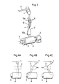
- Fig. 3 shows another mode of embodiment of the present invention.
- a helical continuing curved guide surface 12 is used instead of the abovementioned guide rollers as a traverse guide unit.
- This curved guide surface 12 is formed so that an angle ⁇ a of a surface 12a, onto which a tape type carbon fiber bundle F is initially introduced, with respect to the axial direction of a bobbin becomes substantially 90° with an angle ⁇ b of a discharge surface 12b with respect to the axial direction of the bobbin becoming -5° ⁇ 10°.
- the intermediate portion of the guide surface 12 which is between these introduction surface 12a and discharge surface 12b consists of a helically continuing curved surface having a differential angle ( ⁇ a - ⁇ b ).
- the curved guide surface 12 is provided with the above-mentioned traverse guide unit consisting of guide rollers, and it is thereby laterally moved.
- the curved guide surface 12 mentioned above is adapted to guide the tapetype carbon fiber bundle F, which is fed from the supply roller 1, and apply a twisting force to the flat surface thereof forcibly and gradually, whereby the flat surface can be set parallel to the axial direction of the bobbin on the discharge surface 12b.
- Such a traverse guide unit 2 may be of a plate type as shown in Fig. 5, and it may also be of a box type the front and rear sides of which being covered with walls.
- a box type traverse guide unit the fiber bundle is restricted by the inner surfaces of the front and rear walls while it is traversed, and, therefore, it becomes unnecessary to provide any auxiliary bundle displacement preventing member.
- a plate type traverse guide unit it is necessary to provide the introduction portion of the curved guide surfac 12 with a pair of guide rollers 9 as bundle displacement preventing members.
- Such a displacement preventing means may consist of a slit type or comb type guide.
- the flat surface of the tape type carbon fiber bundle can also be set parallel at all times to the axial direction of the bobbin, so that the occurrence of folds at the fold-back end of the traversed fiber bundle can be prevented, in the same manner as in the previously described embodiment. It is preferable that the curved guide surface be formed out of a selected material having high frictional resistance and surface smoothness.
- the flat surface of the tape type non-twisted carbon fiber bundle is laminated regularly in a diagonally crossing state, and the width We of the portion of the fiber bundle which is wound at an end portion of the package and that Wc of the portion thereof which is wound at the intermediate portion of the package are substantially equal to each other.
- the relation between the width We of the portion of the fiber bundle which is wound at an end portion of the package and that Wc of the portion thereof which is wound at the intermediate portion of the package can be set to We ⁇ Wc x 0.9. Accordingly, folds do not occur in the carbon fiber bundle, and the width of the fiber bundle is constant, i.e., does not vary in the lengthwise direction thereof.
- a tape type non-twisted carbon fiber bundle taken up by the take-up apparatus according to the present invention preferably has a comparatively high rigidity.
- a carbon fiber bundle having a K-value which is representative of its rigidity, and which will be described as follows, of not less than 10 cm is recommended. If the rigidity of a carbon fiber bundle is set to a K-value of not less than 10 cm, each filament in the fiber bundle becomes difficult to be moved. Therefore, the disarray of the regularly arranged fibers can substantially be prevented when the fiber bundle is taken up by the take-up apparatus, or when the fiber bundle is released from the package obtained. This enables a package free from the occurrence of folds on the carbon fiber bundle and variation of the width of the carbon fiber bundle in the lengthwise direction thereof to be obtained more easily.
- the K-value referred to above is determined by a measuring instrument shown in Fig. 8.
- This measuring instrument consists of a block type measuring base 21 having a setting surface 21a on which a sample S of a carbon fiber bundle F is fixed, and a measuring surface 21b, which are formed at 90° to each other.
- a sample S of a carbon fiber bundle is set straight in an atmosphere of 22 ⁇ 3 °C and 60 ⁇ 5 % RH before the measurement of the sample S is conducted, by suspending a load of 0.005 g/d from the sample for 15 minutes.
- the sample S of fiber bundle is then fixed on the setting surface 21a of the measuring base 21 by a fixing member 22 so that the length of the portion of the sample S which projects from the measuring surface 21b becomes 25 cm.
- the sample S of carbon fiber bundle continues to curve at its laterally extending free end portion in the downward direction as shown in the drawing.
- a horizontal distance K between the measuring surface 21b and the free end of the sample S is measured.
- a measurement value thus obtained and expressed in terms of centimeters is determined as a K value..
- Folds on carbon fiber bundle Number of folds appeared on a fiber bundle per 100 turns of windings thereof when the fiber bundle was released from a package thereof.
- Width of carbon fiber bundle A fiber bundle was withdrawn intermittently from a package thereof in the left and right fiber bundle traversing direction and observed at such 20 portions of the fiber bundle with respect to each fiber bundle traversing direction that correspond to the ends of every one turn of the fiber bundle, by magnifying these portions with a magnifying glass of magnifying power of 4.
- the width of the fiber bundle is measured with a scale graduated in 5 mm, and the measurement results were expressed in 0.1 mm.
- the measurement values (in millimeters) obtained at 20 portions of the fiber bundle were averaged, and the average vlues were shown as object values.
- Appearance of wound fiber bundle Package having a difference in the fiber bundle winding tightness between the left and right portions thereof and being likely to come loose was rated "bad".
- This tape type non-twisted carbon fiber bundle was prepared by baking 12000-filament polyacrylonitrile fiber yarn of a fineness of 1.3 denier by a regular method, and the resultant fiber yarn was introduced into a bath of a concentration of 3 % by weight of diglycidyl ether bisphenol A type epoxy resin so as to be subjected to a sizing treatment.
- the resultant fiber bundle had a weight of per unit length of 0.8 g/m.
- the guide rollers in the above-mentioned traverse guide unit consisted of five SUS rollers of 15 mm in diameter and 30 mm in length, and were assembled by disposing the same rotatably so that a minimum distance between two adjacent rollers became 20 mm as shown in Fig. 2. These guide rollers were disposed incliningly so that the angles of inclination ⁇ 1, ⁇ e of an introduction guide roller and a final guide roller were 90° and -5°, respectively.
- a carbon fiber bundle was withdrawn from a package obtained from each take-up apparatus, and the width We (mm) of the portion of the fiber bundle which corresponded to an end portion of the package and that Wc (mm) of the portion of the fiber bundle which corresponded to an intermediate portion thereof, and the number of folds found on the fiber bundle were determined.
- Table 1 The results shown in Table 1 were obtained.
- Take-up apparatuses were set up so that they had the same conditions as the apparatus used in Example 1 except that a maximum difference between the angles of guide rollers was set to 35° with the angle ⁇ e only of a final guide roller set to different levels in different apparatuses, and a tape type non-twisted carbon fiber bundle which was identical with the fiber bundle in Example 1 was taken up under the same take-up conditions.
- the carbon fiber bundle was released from a package obtained in each take-up apparatus to check the number of folds thereon, determine the width thereof and evaluate the appearnace of the winding thereof.
- the results shown in Table 2 were obtained.
- Example 2 The same tape type non-twisted carbon fiber bundle as in Example 1 was taken up under the same take-up conditions therein with a maximum difference between the angles of the guide rollers in the travere guide unit set to 30°.
- a winding twill angle was varied to 5°, 10°, 20°, 25° and 30° in accordance with a fiber bundle traversing speed. As a result, no folds were found on the fiber bundle taken up with a twill angle of not more than 20°, and folds occurred on the fiber bundle taken up with a twill angle of not less than 25°.
- Example 2 The same tape type non-twisted carbon fiber bundle as in Example 1 was taken up under the same take-up conditions therein except that the take-up apparatus shown in Fig. 6 and having a pair of traverse guide rollers of 20 mm in diameter was used.
- the fiber bundle was released from the package obtained, and the condition of occurrence of folds thereon was checked. It was ascertained that the fiber bundle had 131 folds. It was also ascertained that the width of the fiber bundle varied in its lengthwise direction in the range of 4.1 to 5.5 mm.
- a flat SUS plate 50 mm in width and 20 cm in length was twisted helically to form a curved surface shown in Fig. 3.
- An angle ⁇ a of its introduction surface portion and an angle ⁇ b of its discharge surface portion were set different as shown in Table 3.
- a pair of guide rollers 10 mm in diameter were provided above the introduction surface portion.
- Take-up apparatuses (for Examples 10 to 12 and Comparative Examples 8 to 9) provided with such parts were made. The same tape type non-twisted carbon fiber bundle as in Example 1 was taken up under the same take-up conditions in each of these take-up apparatuses.
- Example 2 The same carbon fiber bundles as in Example 1 were subjected to a sizing treatment. The resultant fiber bundles were then subjected to a heat treatment and a drying treatment with the conditions for these steps set differently. Consequently, tape type non-twisted carbin fiber bundles having different K values shown in Table 4 were obtained. These fiber bundles were then taken up by the same take-up appratus as in Example 1 under the same take-up conditions.
- the fiber bundle was released from each package, and a prepreg in which a plurality of fiber bundles were arranged in one direction was made.
- the external appearance of the prepreg was observed, and the variation of the width of per one bundle in the prepreg was determined.
- Table 4 The results shown in Table 4 were obtained.
Landscapes
- Engineering & Computer Science (AREA)
- Mechanical Engineering (AREA)
- Guides For Winding Or Rewinding, Or Guides For Filamentary Materials (AREA)
- Filamentary Materials, Packages, And Safety Devices Therefor (AREA)
- Yarns And Mechanical Finishing Of Yarns Or Ropes (AREA)
- Chemical Treatment Of Fibers During Manufacturing Processes (AREA)
- Nonwoven Fabrics (AREA)
- Treatment Of Fiber Materials (AREA)
- Reinforced Plastic Materials (AREA)
Applications Claiming Priority (2)
| Application Number | Priority Date | Filing Date | Title |
|---|---|---|---|
| JP131912/90 | 1990-05-21 | ||
| JP2131912A JPH0759458B2 (ja) | 1990-05-21 | 1990-05-21 | 開繊性の優れた無撚炭素繊維パッケージ |
Publications (3)
| Publication Number | Publication Date |
|---|---|
| EP0459681A1 true EP0459681A1 (de) | 1991-12-04 |
| EP0459681B1 EP0459681B1 (de) | 1994-12-07 |
| EP0459681B2 EP0459681B2 (de) | 1997-10-08 |
Family
ID=15069090
Family Applications (1)
| Application Number | Title | Priority Date | Filing Date |
|---|---|---|---|
| EP91304566A Expired - Lifetime EP0459681B2 (de) | 1990-05-21 | 1991-05-21 | Vorrichtung zum Wickeln und Verpacken von aus Kohlenstoff bestehenden bandförmigen Faserbündeln |
Country Status (6)
| Country | Link |
|---|---|
| US (2) | US5499776A (de) |
| EP (1) | EP0459681B2 (de) |
| JP (1) | JPH0759458B2 (de) |
| KR (1) | KR100192848B1 (de) |
| DE (1) | DE69105626T3 (de) |
| TW (1) | TW201797B (de) |
Cited By (5)
| Publication number | Priority date | Publication date | Assignee | Title |
|---|---|---|---|---|
| WO2005073118A1 (ja) | 2004-01-28 | 2005-08-11 | Toray Industries, Inc. | 糸道ガイド、繊維束の綾振り装置および繊維束パッケージの製造装置 |
| EP1584594A1 (de) * | 2004-03-10 | 2005-10-12 | Mitsubishi Rayon Co., Ltd. | Führungsvorrichtung für einen kontinuierlichen Faserbündel, Wickelmaschine für einen kontinuierlichen Faserbündel ausgerüstet mit der Führungsvorrichtung, Verfahren zur Herstellung einer Spule mit der Wickelmaschine und Carbonfaserspule hergestellt mit dem Verfahren |
| KR100934950B1 (ko) * | 2008-08-11 | 2010-01-06 | (주)나재 | 인서트 몰딩의 비틀림 가공 장치 |
| CN110884942A (zh) * | 2019-12-06 | 2020-03-17 | 徐州达济电子科技有限公司 | 一种弱电工程施工布线盒 |
| CN115872053A (zh) * | 2023-02-20 | 2023-03-31 | 中国工程物理研究院激光聚变研究中心 | 一种微纳尺度下的弱刚度连接件转运工装 |
Families Citing this family (15)
| Publication number | Priority date | Publication date | Assignee | Title |
|---|---|---|---|---|
| CZ173597A3 (cs) * | 1996-09-13 | 1998-07-15 | Kikuchi Web Tech. Co., Ltd. | Způsob zpracování tkaného materiálu pásového typu a zařízení pro jeho provádění |
| DE19925339C2 (de) * | 1999-06-02 | 2003-02-27 | Lohmann Therapie Syst Lts | Verfahren und Vorrichtung zum Herstellen eines Produktes aus Streifenband, insbesondere eines medizinischen und/oder wirkstoffhaltigen Produktes sowie befüllbaren Behältern oder Siegelrandbeuteln |
| JP3894035B2 (ja) * | 2001-07-04 | 2007-03-14 | 東レ株式会社 | 炭素繊維強化基材、それからなるプリフォームおよび複合材料 |
| US6733831B2 (en) * | 2001-10-30 | 2004-05-11 | Nordson Corporation | Method and apparatus for use in coating elongated bands |
| JP5431726B2 (ja) | 2005-06-23 | 2014-03-05 | コーニンクレッカ フィリップス エヌ ヴェ | 画像および関連データの組み合わされた交換 |
| PT1980518T (pt) * | 2006-01-30 | 2017-05-08 | Toray Industries | Guia-fio transversal |
| DE102012215772B3 (de) | 2012-09-05 | 2013-12-24 | Georg Sahm Gmbh & Co. Kg | Spulgut-Spreizeinrichtung |
| JP6098791B2 (ja) * | 2012-10-12 | 2017-03-22 | オムロン株式会社 | 板材ボビン及び付属装置 |
| CN103266412B (zh) * | 2013-05-31 | 2014-08-06 | 常州市润源经编机械有限公司 | 经编机碳纤维纱用导向辊结构 |
| CN103420198B (zh) * | 2013-08-30 | 2016-08-10 | 严斯亮 | 一种摆臂式柔性带料捆状绕制机 |
| US10239726B2 (en) | 2016-06-15 | 2019-03-26 | Dynamex Corporation | Ribbon self-orienting device for traversed rolls |
| JP6334073B1 (ja) * | 2016-08-25 | 2018-05-30 | ジャパンマテックス株式会社 | 撚糸、開繊糸、炭素繊維被覆撚糸、及びそれらの製造方法 |
| US11027500B1 (en) * | 2017-06-19 | 2021-06-08 | Triad National Security, Llc | Construction of structures by joining of pre-formed tape |
| US20200347522A1 (en) * | 2018-01-26 | 2020-11-05 | Toray Industries, Inc. | Reinforcing fiber bundle |
| CN117342337B (zh) * | 2023-12-05 | 2024-02-06 | 常州市新创智能科技有限公司 | 一种大丝束碳纤维原丝防加捻收卷装置设计方法 |
Citations (4)
| Publication number | Priority date | Publication date | Assignee | Title |
|---|---|---|---|---|
| GB657298A (en) * | 1948-01-23 | 1951-09-19 | Holoplast Ltd | An improved method and means for manufacturing laminated tubes from flexible strip material |
| US3099190A (en) * | 1961-02-01 | 1963-07-30 | Smith Corp A O | Strip winding apparatus |
| US3707415A (en) * | 1968-09-20 | 1972-12-26 | Hercules Inc | Filament winding |
| FR2285982A1 (fr) * | 1974-09-27 | 1976-04-23 | Semperit Ag | Procede et dispositif pour fabriquer des objets de forme allongee, notamment des tuyaux |
Family Cites Families (22)
| Publication number | Priority date | Publication date | Assignee | Title |
|---|---|---|---|---|
| US1827079A (en) * | 1927-09-16 | 1931-10-13 | Frank A Fahrenwald | Furnace |
| US1867596A (en) * | 1930-04-21 | 1932-07-19 | Roseman Leo | Tape winding apparatus |
| US2135668A (en) * | 1936-05-29 | 1938-11-08 | Oscar I Judelshon | Spooling machine |
| US2345544A (en) * | 1942-06-17 | 1944-03-28 | Du Pont | Yarn winding |
| US2451533A (en) * | 1945-10-17 | 1948-10-19 | Celanese Corp | Method of producing improved yarn |
| US2972796A (en) * | 1958-06-20 | 1961-02-28 | Du Pont | Process and apparatus for handling yarns |
| FR1378664A (fr) * | 1963-12-31 | 1964-11-13 | Licentia Gmbh | Dispositif d'enroulement pour presser axialement les uns contre les autres les fils métalliques d'un enroulement tubulaire |
| US3371877A (en) * | 1965-05-14 | 1968-03-05 | Owens Corning Fiberglass Corp | Method for packaging multistrand roving |
| US3365145A (en) * | 1965-05-14 | 1968-01-23 | Owens Corning Fiberglass Corp | Filamentary roving package |
| US3466716A (en) * | 1967-06-02 | 1969-09-16 | Du Pont | Twisted chute for improved tow stacking |
| US3438587A (en) * | 1967-08-04 | 1969-04-15 | American Air Filter Co | Method for making a filamentous mat |
| DE1928188A1 (de) * | 1969-06-03 | 1970-12-23 | Windmoeller & Hoelscher | Flachlege- und Abzugsvorrichtung fuer im Blasverfahren hergestellte Kunststoffschlauchfolien |
| US3802615A (en) * | 1973-02-26 | 1974-04-09 | Eastman Kodak Co | Flexible strip threading guide |
| US3997122A (en) * | 1975-12-15 | 1976-12-14 | Magna Ply | Method and apparatus for wrapping multiple tapes upon an elongated structure |
| US4040575A (en) * | 1976-04-29 | 1977-08-09 | Ampex Corporation | Tape guiding structure |
| SU1102760A1 (ru) * | 1981-07-21 | 1984-07-15 | Всесоюзный ордена Ленина научно-исследовательский и проектно-конструкторский институт металлургического машиностроения | Устройство дл намотки ленты на оправку |
| US4802636A (en) * | 1982-01-26 | 1989-02-07 | Kimberly-Clark Corporation | Method and apparatus for level winding elastomeric ribbon |
| US4489901A (en) * | 1983-05-17 | 1984-12-25 | Allegheny Ludlum Steel Corporation | Coil winding apparatus |
| US4586679A (en) * | 1984-02-06 | 1986-05-06 | Toray Industries, Inc. | Yarn package of carbon filament yarn |
| US4645135A (en) * | 1984-12-13 | 1987-02-24 | Kimberly-Clark Corporation | Method for winding elastomeric ribbon |
| US4989799A (en) * | 1988-12-26 | 1991-02-05 | Kamitsu Seisakusho Ltd. | Apparatus for winding a multifilament with flat shape and broad width |
| US5315461A (en) * | 1992-06-26 | 1994-05-24 | Storage Technology Corporation | Method and apparatus for eliminating the effect of staggerwrap on tape guidance |
-
1990
- 1990-05-21 JP JP2131912A patent/JPH0759458B2/ja not_active Expired - Lifetime
-
1991
- 1991-04-27 TW TW080109567A patent/TW201797B/zh not_active IP Right Cessation
- 1991-05-20 KR KR1019910008194A patent/KR100192848B1/ko not_active IP Right Cessation
- 1991-05-21 EP EP91304566A patent/EP0459681B2/de not_active Expired - Lifetime
- 1991-05-21 DE DE69105626T patent/DE69105626T3/de not_active Expired - Lifetime
-
1992
- 1992-09-14 US US07/944,736 patent/US5499776A/en not_active Expired - Lifetime
-
1994
- 1994-03-17 US US08/214,181 patent/US5487512A/en not_active Expired - Lifetime
Patent Citations (4)
| Publication number | Priority date | Publication date | Assignee | Title |
|---|---|---|---|---|
| GB657298A (en) * | 1948-01-23 | 1951-09-19 | Holoplast Ltd | An improved method and means for manufacturing laminated tubes from flexible strip material |
| US3099190A (en) * | 1961-02-01 | 1963-07-30 | Smith Corp A O | Strip winding apparatus |
| US3707415A (en) * | 1968-09-20 | 1972-12-26 | Hercules Inc | Filament winding |
| FR2285982A1 (fr) * | 1974-09-27 | 1976-04-23 | Semperit Ag | Procede et dispositif pour fabriquer des objets de forme allongee, notamment des tuyaux |
Cited By (10)
| Publication number | Priority date | Publication date | Assignee | Title |
|---|---|---|---|---|
| WO2005073118A1 (ja) | 2004-01-28 | 2005-08-11 | Toray Industries, Inc. | 糸道ガイド、繊維束の綾振り装置および繊維束パッケージの製造装置 |
| EP1710188A1 (de) * | 2004-01-28 | 2006-10-11 | Toray Industries, Inc. | Fadenhandhabungsbereichsführung, querbewegungseinheit für faserbündel und system zur herstellung eines faserbündelpakets |
| EP1710188A4 (de) * | 2004-01-28 | 2008-10-08 | Toray Industries | Fadenhandhabungsbereichsführung, querbewegungseinheit für faserbündel und system zur herstellung eines faserbündelpakets |
| EP1584594A1 (de) * | 2004-03-10 | 2005-10-12 | Mitsubishi Rayon Co., Ltd. | Führungsvorrichtung für einen kontinuierlichen Faserbündel, Wickelmaschine für einen kontinuierlichen Faserbündel ausgerüstet mit der Führungsvorrichtung, Verfahren zur Herstellung einer Spule mit der Wickelmaschine und Carbonfaserspule hergestellt mit dem Verfahren |
| US7255302B2 (en) | 2004-03-10 | 2007-08-14 | Mitsubishi Rayon Co., Ltd. | Guide apparatus for continuous fiber bundle, winding machine for continuous fiber bundle equipped with the guide apparatus, method for making bobbin by the winding machine, and carbon fiber bobbin made by the method |
| CN100364871C (zh) * | 2004-03-10 | 2008-01-30 | 三菱丽阳株式会社 | 连续纤维束的导向装置、卷绕机、碳纤维绕线筒及其制法 |
| KR100934950B1 (ko) * | 2008-08-11 | 2010-01-06 | (주)나재 | 인서트 몰딩의 비틀림 가공 장치 |
| CN110884942A (zh) * | 2019-12-06 | 2020-03-17 | 徐州达济电子科技有限公司 | 一种弱电工程施工布线盒 |
| CN115872053A (zh) * | 2023-02-20 | 2023-03-31 | 中国工程物理研究院激光聚变研究中心 | 一种微纳尺度下的弱刚度连接件转运工装 |
| CN115872053B (zh) * | 2023-02-20 | 2024-04-19 | 中国工程物理研究院激光聚变研究中心 | 一种微纳尺度下的弱刚度连接件转运工装 |
Also Published As
| Publication number | Publication date |
|---|---|
| US5487512A (en) | 1996-01-30 |
| DE69105626D1 (de) | 1995-01-19 |
| TW201797B (de) | 1993-03-11 |
| DE69105626T3 (de) | 1998-03-12 |
| US5499776A (en) | 1996-03-19 |
| JPH0759458B2 (ja) | 1995-06-28 |
| DE69105626T2 (de) | 1995-04-20 |
| KR910019881A (ko) | 1991-12-19 |
| KR100192848B1 (ko) | 1999-06-15 |
| EP0459681B1 (de) | 1994-12-07 |
| JPH0424264A (ja) | 1992-01-28 |
| EP0459681B2 (de) | 1997-10-08 |
Similar Documents
| Publication | Publication Date | Title |
|---|---|---|
| EP0459681B1 (de) | Vorrichtung zum Wickeln und Verpacken von aus Kohlenstoff bestehenden bandförmigen Faserbündeln | |
| JP5148734B2 (ja) | 連続繊維束のガイド装置を備えた連続繊維束巻取機と同機によるボビンの製造方法、及び同製造方法により得られる炭素繊維ボビン | |
| US5957402A (en) | Method and apparatus for reducing catenary during winding of a fiber bundle | |
| JP2909294B2 (ja) | ガラスヤーンの製造方法 | |
| US4471917A (en) | Balloon-control guide and yarn rewinding process | |
| JP3189180B2 (ja) | 仮撚糸巻き取りパッケージ | |
| US3383851A (en) | Method of producing roving | |
| JP6728889B2 (ja) | 筒体の製造装置およびその製造方法 | |
| US4186549A (en) | Packaging of self-twist yarns | |
| JP4618132B2 (ja) | 糸道ガイド、繊維束パッケージの製造方法および製造装置 | |
| JP3698227B2 (ja) | 連続繊維束の巻取り装置 | |
| US3545192A (en) | Apparatus for winding roving | |
| US4519195A (en) | Helical wrapping of tape | |
| JP2001348166A (ja) | 巻取り機用ガイド装置と巻取り機 | |
| JP2005225644A (ja) | 巻取機用綾振りガイド装置および巻取機と炭素繊維束パッケージの製造方法 | |
| JP2845636B2 (ja) | 繊維糸条巻取機用トラバースガイド | |
| JP3656871B2 (ja) | 炭素繊維パッケージおよびその製造方法 | |
| US2738144A (en) | Textile package | |
| JPS5928512B2 (ja) | ガラス長繊維ノンツイストロ−ビング製品の製造方法 | |
| US3271825A (en) | Method of conditioning glass fiber strands | |
| JP2662478B2 (ja) | 金属コード用トラバースローラ | |
| JP5034448B2 (ja) | 炭素繊維パッケージの製造方法 | |
| JP2004076246A (ja) | 炭素繊維束 | |
| JPH0797138A (ja) | 炭素繊維の無芯パッケージ | |
| JP3332191B2 (ja) | ガラス繊維回巻体 |
Legal Events
| Date | Code | Title | Description |
|---|---|---|---|
| PUAI | Public reference made under article 153(3) epc to a published international application that has entered the european phase |
Free format text: ORIGINAL CODE: 0009012 |
|
| AK | Designated contracting states |
Kind code of ref document: A1 Designated state(s): DE FR GB NL |
|
| 17P | Request for examination filed |
Effective date: 19920520 |
|
| 17Q | First examination report despatched |
Effective date: 19930720 |
|
| GRAA | (expected) grant |
Free format text: ORIGINAL CODE: 0009210 |
|
| AK | Designated contracting states |
Kind code of ref document: B1 Designated state(s): DE FR GB NL |
|
| REF | Corresponds to: |
Ref document number: 69105626 Country of ref document: DE Date of ref document: 19950119 |
|
| ET | Fr: translation filed | ||
| PLBI | Opposition filed |
Free format text: ORIGINAL CODE: 0009260 |
|
| 26 | Opposition filed |
Opponent name: TENAX FIBERS GMBH & CO.KG Effective date: 19950829 |
|
| NLR1 | Nl: opposition has been filed with the epo |
Opponent name: TENAX FIBERS GMBH & CO.KG |
|
| PLBF | Reply of patent proprietor to notice(s) of opposition |
Free format text: ORIGINAL CODE: EPIDOS OBSO |
|
| PLBF | Reply of patent proprietor to notice(s) of opposition |
Free format text: ORIGINAL CODE: EPIDOS OBSO |
|
| PLAW | Interlocutory decision in opposition |
Free format text: ORIGINAL CODE: EPIDOS IDOP |
|
| PLAW | Interlocutory decision in opposition |
Free format text: ORIGINAL CODE: EPIDOS IDOP |
|
| PUAH | Patent maintained in amended form |
Free format text: ORIGINAL CODE: 0009272 |
|
| STAA | Information on the status of an ep patent application or granted ep patent |
Free format text: STATUS: PATENT MAINTAINED AS AMENDED |
|
| 27A | Patent maintained in amended form |
Effective date: 19971008 |
|
| AK | Designated contracting states |
Kind code of ref document: B2 Designated state(s): DE FR GB NL |
|
| NLR2 | Nl: decision of opposition | ||
| ET3 | Fr: translation filed ** decision concerning opposition | ||
| NLR3 | Nl: receipt of modified translations in the netherlands language after an opposition procedure | ||
| REG | Reference to a national code |
Ref country code: GB Ref legal event code: IF02 |
|
| PGFP | Annual fee paid to national office [announced via postgrant information from national office to epo] |
Ref country code: GB Payment date: 20100329 Year of fee payment: 20 |
|
| PGFP | Annual fee paid to national office [announced via postgrant information from national office to epo] |
Ref country code: FR Payment date: 20100525 Year of fee payment: 20 |
|
| PGFP | Annual fee paid to national office [announced via postgrant information from national office to epo] |
Ref country code: NL Payment date: 20100501 Year of fee payment: 20 Ref country code: DE Payment date: 20100519 Year of fee payment: 20 |
|
| REG | Reference to a national code |
Ref country code: DE Ref legal event code: R071 Ref document number: 69105626 Country of ref document: DE |
|
| REG | Reference to a national code |
Ref country code: NL Ref legal event code: V4 Effective date: 20110521 |
|
| REG | Reference to a national code |
Ref country code: GB Ref legal event code: PE20 Expiry date: 20110520 |
|
| PG25 | Lapsed in a contracting state [announced via postgrant information from national office to epo] |
Ref country code: NL Free format text: LAPSE BECAUSE OF EXPIRATION OF PROTECTION Effective date: 20110521 Ref country code: GB Free format text: LAPSE BECAUSE OF EXPIRATION OF PROTECTION Effective date: 20110520 |
|
| PG25 | Lapsed in a contracting state [announced via postgrant information from national office to epo] |
Ref country code: DE Free format text: LAPSE BECAUSE OF EXPIRATION OF PROTECTION Effective date: 20110522 |