EP0459544A2 - Werkzeugmaschine mit verschiebbarer Positionierungsvorrichtung - Google Patents
Werkzeugmaschine mit verschiebbarer Positionierungsvorrichtung Download PDFInfo
- Publication number
- EP0459544A2 EP0459544A2 EP91200959A EP91200959A EP0459544A2 EP 0459544 A2 EP0459544 A2 EP 0459544A2 EP 91200959 A EP91200959 A EP 91200959A EP 91200959 A EP91200959 A EP 91200959A EP 0459544 A2 EP0459544 A2 EP 0459544A2
- Authority
- EP
- European Patent Office
- Prior art keywords
- carrier
- frame
- machine tool
- workpiece
- positioning device
- Prior art date
- Legal status (The legal status is an assumption and is not a legal conclusion. Google has not performed a legal analysis and makes no representation as to the accuracy of the status listed.)
- Granted
Links
- 230000008878 coupling Effects 0.000 claims abstract description 40
- 238000010168 coupling process Methods 0.000 claims abstract description 40
- 238000005859 coupling reaction Methods 0.000 claims abstract description 40
- 239000012530 fluid Substances 0.000 claims abstract description 19
- 230000003068 static effect Effects 0.000 claims abstract description 11
- 238000003754 machining Methods 0.000 claims abstract description 10
- 238000006073 displacement reaction Methods 0.000 abstract description 4
- 238000010276 construction Methods 0.000 description 2
- 238000005520 cutting process Methods 0.000 description 2
- 230000033001 locomotion Effects 0.000 description 2
- 230000002411 adverse Effects 0.000 description 1
- 230000005540 biological transmission Effects 0.000 description 1
- 230000000295 complement effect Effects 0.000 description 1
- 230000013011 mating Effects 0.000 description 1
Images
Classifications
-
- B—PERFORMING OPERATIONS; TRANSPORTING
- B23—MACHINE TOOLS; METAL-WORKING NOT OTHERWISE PROVIDED FOR
- B23Q—DETAILS, COMPONENTS, OR ACCESSORIES FOR MACHINE TOOLS, e.g. ARRANGEMENTS FOR COPYING OR CONTROLLING; MACHINE TOOLS IN GENERAL CHARACTERISED BY THE CONSTRUCTION OF PARTICULAR DETAILS OR COMPONENTS; COMBINATIONS OR ASSOCIATIONS OF METAL-WORKING MACHINES, NOT DIRECTED TO A PARTICULAR RESULT
- B23Q1/00—Members which are comprised in the general build-up of a form of machine, particularly relatively large fixed members
- B23Q1/0063—Connecting non-slidable parts of machine tools to each other
-
- Y—GENERAL TAGGING OF NEW TECHNOLOGICAL DEVELOPMENTS; GENERAL TAGGING OF CROSS-SECTIONAL TECHNOLOGIES SPANNING OVER SEVERAL SECTIONS OF THE IPC; TECHNICAL SUBJECTS COVERED BY FORMER USPC CROSS-REFERENCE ART COLLECTIONS [XRACs] AND DIGESTS
- Y10—TECHNICAL SUBJECTS COVERED BY FORMER USPC
- Y10T—TECHNICAL SUBJECTS COVERED BY FORMER US CLASSIFICATION
- Y10T409/00—Gear cutting, milling, or planing
- Y10T409/30—Milling
- Y10T409/309576—Machine frame
- Y10T409/309912—Machine frame including relatively movable components and means to relatively immobilize these components
-
- Y—GENERAL TAGGING OF NEW TECHNOLOGICAL DEVELOPMENTS; GENERAL TAGGING OF CROSS-SECTIONAL TECHNOLOGIES SPANNING OVER SEVERAL SECTIONS OF THE IPC; TECHNICAL SUBJECTS COVERED BY FORMER USPC CROSS-REFERENCE ART COLLECTIONS [XRACs] AND DIGESTS
- Y10—TECHNICAL SUBJECTS COVERED BY FORMER USPC
- Y10T—TECHNICAL SUBJECTS COVERED BY FORMER US CLASSIFICATION
- Y10T82/00—Turning
- Y10T82/25—Lathe
- Y10T82/2531—Carriage feed
- Y10T82/2541—Slide rest
-
- Y—GENERAL TAGGING OF NEW TECHNOLOGICAL DEVELOPMENTS; GENERAL TAGGING OF CROSS-SECTIONAL TECHNOLOGIES SPANNING OVER SEVERAL SECTIONS OF THE IPC; TECHNICAL SUBJECTS COVERED BY FORMER USPC CROSS-REFERENCE ART COLLECTIONS [XRACs] AND DIGESTS
- Y10—TECHNICAL SUBJECTS COVERED BY FORMER USPC
- Y10T—TECHNICAL SUBJECTS COVERED BY FORMER US CLASSIFICATION
- Y10T82/00—Turning
- Y10T82/25—Lathe
- Y10T82/2566—Bed
Definitions
- the invention relates to a machine tool for machining a workpiece which is fastened to a rotatable support which has its bearings in a frame of the machine tool, which machine tool is provided with a positioning device for locating a tool fastened on the positioning device relative to the workpiece, the tool being movable in at least an x-direction by means of the positioning device.
- a tool such as a chisel is fastened to a transverse carriage which is movably guided along a straight guide of a longitudinal carriage in a direction transverse to a direction of a horizontal axis of rotation of the rotatable support of the workpiece.
- the longitudinal carriage of such a machine is movably guided along a straight guide of a frame of the machine.
- Such machine tools are in general only suitable for machining workpieces of a comparatively small diameter.
- the invention has for its object inter alia to provide a machine tool in which the disadvantages described above are avoided.
- the machine tool is for this purpose characterized in that the positioning device is provided on a carrier which is movable along a flat guide of the frame in a y-direction perpendicular to the x-direction, while the machine tool is provided with coupling members for coupling the carrier to the frame.
- the carrier on which the positioning device is provided When the carrier on which the positioning device is provided is moved relative to the frame and to the workpiece support journalled in the frame before the removal or clamping of the workpiece or the tool, a space between the support and the positioning device is created which is accessible to the machine operator. Since in addition the carrier can be coupled to the frame and forces exerted on the tool can be transmitted to the frame via the coupling members provided for that purpose, a high degree of rigidity is achieved and an accurate machining of the workpiece is possible.
- a particular embodiment of a machine tool according to the invention which provides a substantially frictionless guiding of the carrier of the positioning device along the frame is characterized in that the carrier is guided along the flat guide of the frame by means of a static fluid bearing.
- the static fluid bearing is not operational, but the bearing can be made operational by a supply of fluid under pressure to this bearing after the carrier has been uncoupled from the frame, so that the carrier can then be moved along the guide of the frame by the exertion of a small force.
- a further embodiment of a machine tool according to the invention which provides a particularly sturdy, effective and easily realisable coupling between the carrier and the frame of the machine tool is characterized in that the coupling members for coupling the carrier to the frame are provided with bolts attached to the carrier, which bolts are couplable to fastening members of the frame, each bolt being subjected to a tensile stress during operation after coupling to the frame, which tensile stress is achieved by means of a piston which is movable by a fluid in a cylinder and is connected to the relevant bolt.
- a still further embodiment of a machine tool according to the invention which provides a simple construction of the coupling members for coupling the carrier to the frame is characterized in that each of the cylinders is attached to the carrier, while a head of each bolt constitutes the piston by means of which the tensile stress is applied to the relevant bolt during operation.
- a particular embodiment of a machine tool according to the invention is characterized in that the cylinders are pivotably coupled to the carrier.
- the use of a pivotable coupling of the cylinders to the carrier prevents undesirable stresses which may occur in the coupling members by which the carrier can be coupled to the frame.
- a further embodiment of a machine tool according to the invention is characterized in that the carrier and the fastening members of the frame are provided mutually fitting with curved support surfaces which are in pressure contact with one another after coupling of the carrier to the frame and which extend around the bolts. It is achieved in this way that the carrier with the positioning device provided on it can be brought into an accurate position relative to the frame and the workpiece support having its bearings therein while being coupled to the frame.
- the use of the said support surfaces achieves that the transmission to the frame of the machining forces exerted on the positioning device can take place over a comparatively large surface. Undesirable pressure concentrations are avoided in this way.
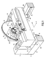
- the embodiment of the machine tool shown in Fig. 1 comprises a frame 1 which is provided with two frame blocks 3 and 5 which are situated at a distance from one another and which extend substantially parallel to one another in a horizontal direction represented as the y-direction in Fig. 1.
- the two frame blocks 3 and 5 are interconnected at one end of each of these frame blocks by means of a cross beam 7 which extends in a horizontal x-direction perpendicular to the y-direction indicated in Fig. 1.
- a vertical, disc-shaped support 9 of a plate-shaped workpiece 11 has its bearings in the cross beam 7 of the frame 1.
- the support 9 is rotatable about an axis of rotation 13, which is substantially parallel to the y-direction, by driving means which are not shown.
- the workpiece 11 in that case is fastened to a side 15 of the support 9 facing away from the cross beam 7.
- a girder 17 (carrier) is provided at the side 15 of the support 9, which girder extends in the x-direction parallel to the cross beam 7. Near its two ends, the girder 17 is movably guided along a flat guide 23 of the frame block 3 and a flat guide 25 of the frame block 5 by means of static fluid bearings 19 and 21, respectively, the guides 23 and 25 being formed by upper surfaces of the frame blocks 3 and 5, which two upper surfaces are situated in a horizontal plane parallel to the x- and y-directions.
- the static fluid bearings 19, 21 are of a type which is known per se and are not indicated further in Fig. 1.
- roller members 27 and 29 which bear on a straight guide rail 31 of the frame block 3 and a straight guide rail 33 of the frame block 5, respectively, the guide rails 31 and 33 extending parallel to the y-direction on the mutually facing lateral surfaces of the frame blocks 3 and 5.
- the girder 17 can be moved by hand by an operator of the machine tool with little force in the y-direction along the frame blocks 3 and 5, undesirable displacements in the x-direction being prevented by the guide rails 31 and 33 and the roller members 27 and 29.
- the girder 17 constitutes a carrier for a positioning device 35 by which a tool 37 fastened to the positioning device 35, such as, for example, a chisel, is movable relative to the workpiece 11.
- the tool 37 is fastened to a ⁇ -carriage 45 of the positioning device 35, which ⁇ carriage is rotatably guided about an axis of rotation 47 indicated in Fig.
- the girder 17 is coupled to the cross beam 7 of the frame 1 by means of coupling members 51 in the operational position of the machine tool represented in Fig. 1.
- the workpiece 11 fastened to the support 9 can be machined by the tool 37 fastened to the positioning device 35 through a rotational movement of the workpiece 11 about the axis of rotation 13, a feed motion of the transverse carriage 43 in the y-direction, and a displacement of the longitudinal carriage 41 in the x-direction.
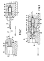
- the coupling members 51 each comprise a first block 53 attached to the girder 17 and comprising a circular cylindrical chamber 55 with a centreline 57 which is parallel to the y-direction.
- a cylinder 59 provided with a circular cylindrical shell 61 whose centreline 63 is situated in a plane transverse to the x-direction and intersects the centreline 57 of the chamber 55 in point of intersection 65, with a ring-shaped bottom 67 transverse to the centreline 63 of the shell 61, and with a head 69 which is hinged on the first block 53 by means of a pivot pin 71 which goes through the point of intersection 65 and extends in the x-direction.
- the chamber 55 surrounds the shell 61 with some clearance, so that the cylinder 59 in the situation represented in Fig. 2 can pivot through small angles about an axis which goes through the intersection point 65 and is parallel to the x-direction.
- a piston 73 is present in the cylinder 59.
- the piston 73 is formed by a head of a bolt 75, while a rod 77 of the piston 73 is formed by a shaft of the bolt 75, whose centreline coincides with the centreline 63 of the cylinder shell 61.
- the rod 77 is provided with screw thread 79 at its free end.
- this block 53 is bounded by a first curved support surface 81 of the block 53, which support surface 81 forms a boundary of a spherical surface whose centre is situated on the centreline 63 of the cylinder shell 61.
- the coupling members 51 each comprise a second block 83 attached to the cross beam 7 of the frame 1.
- a stepped bore is provided in the second block 83, whose centreline coincides with the centreline 57 of the chamber 55 of the first block 53.
- the said stepped bore comprises two bore portions 85 and 87 which are interconnected by a bore portion 89 whose diameter is smaller than the diameters of the bore portions 85 and 87.
- the boundary surface of the support piece 91 facing the girder 17 forms a second curved support surface 93 whose shape is complementary to that of the first support surface 81 of the first block 53.
- the support piece 91 is further provided with a bore 95 which is situated in the extended direction of the bore portion 89 of the second block 83 and whose diameter equals the diameter of the bore portion 89.
- the two mutually fitting curved support surfaces 81 and 93 are in pressure contact with one another in the operational position.
- the support surfaces 81, 93 are manufactured accurately and are provided in an accurate position relative to the girder 17 and the cross beam 7, respectively.
- the girder 17 with the positioning device 35 provided on it is arranged in an accurate position relative to the cross beam 7 of the frame 1 with the support 9 of the workpiece 11 journalled in it, which renders possible an accurate positioning of the tool 37 relative to the workpiece 11 by means of the positioning device 35.
- the fluid present between the pistons 73 and the bottoms 67 in the cylinders 59 of the coupling members 51 is first depressurized, upon which the nuts 97 are unscrewed from the rods 77. Then the static fluid bearings 19 and 21 are activated, after which the girder 17 with the positioning device 35 is moved along the flat guides 23 and 25 of the frame blocks 3 and 5 by hand in a direction away from the support 9 over such a distance that the space thus created between the girder 17 and the support 9 is accessible to the operator for fastening the workpiece to or removing it from the support 9.
- the static fluid bearings 19 and 21 can be de-activated, so that then the girder 17 will rest squarely on the frame blocks 3 and 5.
- the operator of the machine tool is also capable of fastening a tool to or removing it from the positioning device 35 in a simple manner.
- the operator of the machine tool will again activate the static fluid bearings 19 and 21, and move the girder 17 towards the support 9 in such a way that the rods 77 of the coupling members 51 return to the position shown in Fig. 3.
- the nuts 77 are then screwed on the ends of the rods 77 again by hand, after which pressurized fluid is supplied to the cylinders 59 of the coupling members 51 between the pistons 73 and the bottoms 67.
- the rods 77 are tensioned again in this way, so that a rigid and accurate coupling of the girder 17 to the cross beam 7 of the frame 1 is realised.
- the machine tool described above comprises a vertically arranged disc-shaped support on which a plate-shaped workpiece is clamped. More particularly, so-called masters for projection television screens in the form of circular Fresnel lenses are manufactured with these machine tools by means of a cutting operation. It should be noted that other embodiments of machine tools are also possible, provided with a carrier on which a positioning device for a tool is present and which is movable relative to the workpiece, while a space accessible to an operator of the machine tool is created through displacement of the carrier relative to the workpiece.
- the machine tool may be provided with, for instance, a drum-shaped support rotatable about a horizontal axis of rotation with a flexible, plate-shaped workpiece clamped around this support, the carrier of the positioning device being displaceable along a straight guide of the frame in a direction transverse to the said axis of rotation.
- a machine tool for example, masters for linear Fresnel lenses may be manufactured through a cutting operation of the tool.
- the carrier of the positioning device may also be guided along the frame in a conventional manner such as, for example, by means of roller members attached to the carrier and guide rails attached to the frame blocks. If these types of guidance are used, an operator of the machine tool will have to exert a greater force on the carrier when displacing the latter than in the case of static fluid bearings.
- the static fluid bearings by which the carrier of the positioning device is guided along the frame blocks may also be operational in the operational condition of the machine tool described above. Coupling of the carrier to the frame in this condition takes place exclusively through the said coupling members, so that an optimal positioning accuracy is achieved.
- the coupling members described above provide a particularly rigid, accurate, and relatively simple coupling between the carrier and the frame.
- other coupling members such as, for example, coupling members provided with electromagnetic couplings of a known type, may be used.
- An accurate positioning of the carrier relative to the frame may be achieved in a simple manner with the use of these alternative coupling members through the use of the said accurately mating support surfaces.
Landscapes
- Engineering & Computer Science (AREA)
- Mechanical Engineering (AREA)
- Machine Tool Units (AREA)
- Turning (AREA)
Applications Claiming Priority (2)
| Application Number | Priority Date | Filing Date | Title |
|---|---|---|---|
| NL9001014A NL9001014A (nl) | 1990-04-27 | 1990-04-27 | Gereedschapsmachine met verplaatsbare positioneerinrichting. |
| NL9001014 | 1990-04-27 |
Publications (3)
| Publication Number | Publication Date |
|---|---|
| EP0459544A2 true EP0459544A2 (de) | 1991-12-04 |
| EP0459544A3 EP0459544A3 (en) | 1992-07-08 |
| EP0459544B1 EP0459544B1 (de) | 2000-10-11 |
Family
ID=19857019
Family Applications (1)
| Application Number | Title | Priority Date | Filing Date |
|---|---|---|---|
| EP91200959A Expired - Lifetime EP0459544B1 (de) | 1990-04-27 | 1991-04-22 | Werkzeugmaschine mit verschiebbarer Positionierungsvorrichtung |
Country Status (5)
| Country | Link |
|---|---|
| US (1) | US5105693A (de) |
| EP (1) | EP0459544B1 (de) |
| JP (1) | JPH04226801A (de) |
| DE (1) | DE69132440T2 (de) |
| NL (1) | NL9001014A (de) |
Cited By (2)
| Publication number | Priority date | Publication date | Assignee | Title |
|---|---|---|---|---|
| WO1996029176A1 (en) * | 1995-03-17 | 1996-09-26 | The Boeing Company | Self locating device for fixturing very large objects |
| WO2004091862A3 (de) * | 2003-04-15 | 2005-08-25 | Ssa System Spann Ag | Schnellspannzylinder mit führungseinrichtung für den einzugsnippel |
Families Citing this family (5)
| Publication number | Priority date | Publication date | Assignee | Title |
|---|---|---|---|---|
| NL9100439A (nl) * | 1991-03-12 | 1992-10-01 | Philips Nv | Scheerapparaat. |
| US6457919B1 (en) | 1998-08-11 | 2002-10-01 | William D. Sangster | Multi-purpose machine tool for high volume secondary operations |
| US20110123285A1 (en) * | 2007-08-27 | 2011-05-26 | Hiroyuki Matsuda | Multiaxis machining apparatus |
| CN102209941B (zh) * | 2008-09-18 | 2015-05-06 | Flir系统贸易比利时有限公司 | 用于对材料进行机械加工的系统和方法 |
| US9199715B2 (en) * | 2013-10-10 | 2015-12-01 | The Boeing Company | Self-aligning fitting assemblies and systems and methods including the same |
Family Cites Families (16)
| Publication number | Priority date | Publication date | Assignee | Title |
|---|---|---|---|---|
| GB191401109A (en) * | 1913-01-22 | 1915-07-29 | Karl Krug | Improvements in or relating to Grinding Machines. |
| DE665218C (de) * | 1932-12-04 | 1938-09-20 | Friedrich Deckel Praez S Mecha | Fraesmaschine mit waagerechter Arbeitsspindel und einer aufsetzbaren Winkelfraeseinrichtung |
| US2167755A (en) * | 1938-06-16 | 1939-08-01 | Niles Bement Pond Co | Bench lathe |
| FR1165754A (fr) * | 1957-01-31 | 1958-10-29 | Cazeneuve Sa | Dispositif d'asservissement de l'avance des chariots ou autres dans les machinesoutils |
| CH418094A (de) * | 1964-11-13 | 1966-07-31 | Fischer Ag Georg | Verstellvorrichtung an Werkzeugmaschinen |
| GB1148238A (en) * | 1966-10-06 | 1969-04-10 | Hitachi Seiki Kabushiki Kaisha | Improvements in or relating to capstan lathes |
| US3555963A (en) * | 1968-10-01 | 1971-01-19 | Gen Electric | Removable head for a machine tool |
| DE2356799A1 (de) * | 1973-11-14 | 1975-05-15 | Scharmann & Co | Horizontal-bohr- und fraeswerk, mit einem die werkzeuge tragenden werkzeugmagazin |
| US4210038A (en) * | 1977-07-05 | 1980-07-01 | Continuance Curve Contact Lenses, Inc. | Lathe having a guided movable cutter |
| US4209206A (en) * | 1977-08-20 | 1980-06-24 | Rolls-Royce Limited | Rotary mounting for use especially with measuring apparatus |
| JPS57132969A (en) * | 1981-02-03 | 1982-08-17 | Shibayama Kikai Kk | Spindle slant adjusting device in plane or spherical rotor grinder, fine grinding machine, lapping machine and polishing machine |
| EP0083660B1 (de) * | 1981-07-15 | 1989-02-01 | Matsushita Electric Industrial Co., Ltd. | Einrichtung zum positionieren eines kreuztisches |
| JPS59166410A (ja) * | 1983-03-11 | 1984-09-19 | Kawasaki Steel Corp | 溶接装置用切断装置 |
| DE3405601A1 (de) * | 1984-02-16 | 1985-08-22 | Gasa-Produktionsgesellschaft für Sondermaschinen mbH, 8752 Hösbach | Balkenanordnung |
| CH668376A5 (de) * | 1984-10-11 | 1988-12-30 | Schaudt Maschinenbau Gmbh | Schleifmaschine. |
| DE3680205D1 (de) * | 1986-04-17 | 1991-08-14 | Meyer & Burger Ag Maschf | Verfahren zum trennen eines stabes in teilstuecke, trennschleifmaschine zur durchfuehrung dieses verfahrens und verwendung dieser trennschleifmaschine. |
-
1990
- 1990-04-27 NL NL9001014A patent/NL9001014A/nl not_active Application Discontinuation
- 1990-11-26 US US07/619,170 patent/US5105693A/en not_active Expired - Lifetime
-
1991
- 1991-04-22 EP EP91200959A patent/EP0459544B1/de not_active Expired - Lifetime
- 1991-04-22 DE DE69132440T patent/DE69132440T2/de not_active Expired - Fee Related
- 1991-04-26 JP JP3123141A patent/JPH04226801A/ja not_active Ceased
Cited By (3)
| Publication number | Priority date | Publication date | Assignee | Title |
|---|---|---|---|---|
| WO1996029176A1 (en) * | 1995-03-17 | 1996-09-26 | The Boeing Company | Self locating device for fixturing very large objects |
| WO2004091862A3 (de) * | 2003-04-15 | 2005-08-25 | Ssa System Spann Ag | Schnellspannzylinder mit führungseinrichtung für den einzugsnippel |
| US7520495B2 (en) | 2003-04-15 | 2009-04-21 | Ssa System-Spann Ag | Rapid-action clamping cylinder comprising a guiding device |
Also Published As
| Publication number | Publication date |
|---|---|
| EP0459544B1 (de) | 2000-10-11 |
| DE69132440D1 (de) | 2000-11-16 |
| JPH04226801A (ja) | 1992-08-17 |
| DE69132440T2 (de) | 2001-04-26 |
| NL9001014A (nl) | 1991-11-18 |
| US5105693A (en) | 1992-04-21 |
| EP0459544A3 (en) | 1992-07-08 |
Similar Documents
| Publication | Publication Date | Title |
|---|---|---|
| CA1212827A (en) | Motor vehicle body repair bench | |
| JP3452630B2 (ja) | フレキシブル機械加工治具 | |
| EP0459544B1 (de) | Werkzeugmaschine mit verschiebbarer Positionierungsvorrichtung | |
| US4642861A (en) | Machine tool construction | |
| CN112222534A (zh) | 一种用于机械制造的抗震型精雕装置 | |
| JP2000117572A (ja) | 工作機械のパレットクランプ装置 | |
| US5711287A (en) | Reciprocating slurry saw | |
| CN113211143B (zh) | 转向节上下耳内外侧粗铣加工定位装置 | |
| CN209868001U (zh) | 电动门泵减速器壳体的机加工工装 | |
| US4688779A (en) | Machine tool vise | |
| US6824142B2 (en) | Method of alignably supporting a work piece for rotary movements | |
| CN116810450A (zh) | 一种大型零件加工定位装置 | |
| US4269001A (en) | Work clamping fixture | |
| CN212665371U (zh) | 一种加工用的固定设备 | |
| CN217513367U (zh) | 一种支顶式平面定位夹装设备 | |
| CN223338950U (zh) | 一种螺栓钻孔加工定位装置 | |
| CN216729593U (zh) | 一种机床尾座 | |
| JPH091436A (ja) | 工作機械の移動体のクランプ機構 | |
| KR102882716B1 (ko) | 플랜지 홀 가공장치 | |
| RU2116166C1 (ru) | Устройство для обработки направляющих станин | |
| CN222767789U (zh) | 传动轴外壳镗孔加工用定位工装 | |
| CN223684943U (zh) | 一种定位退出支撑不退出夹具夹紧结构 | |
| CN215615248U (zh) | 一种液压支架结构件平行铰接孔加工装置 | |
| CN216028444U (zh) | 一种倒角机及其定位装置 | |
| CN216126844U (zh) | 一种框架加工用辅助治具 |
Legal Events
| Date | Code | Title | Description |
|---|---|---|---|
| PUAI | Public reference made under article 153(3) epc to a published international application that has entered the european phase |
Free format text: ORIGINAL CODE: 0009012 |
|
| AK | Designated contracting states |
Kind code of ref document: A2 Designated state(s): DE FR GB IT |
|
| PUAL | Search report despatched |
Free format text: ORIGINAL CODE: 0009013 |
|
| AK | Designated contracting states |
Kind code of ref document: A3 Designated state(s): DE FR GB IT |
|
| 17P | Request for examination filed |
Effective date: 19921229 |
|
| 17Q | First examination report despatched |
Effective date: 19930716 |
|
| RAP3 | Party data changed (applicant data changed or rights of an application transferred) |
Owner name: KONINKLIJKE PHILIPS ELECTRONICS N.V. |
|
| APAB | Appeal dossier modified |
Free format text: ORIGINAL CODE: EPIDOS NOAPE |
|
| GRAG | Despatch of communication of intention to grant |
Free format text: ORIGINAL CODE: EPIDOS AGRA |
|
| GRAH | Despatch of communication of intention to grant a patent |
Free format text: ORIGINAL CODE: EPIDOS IGRA |
|
| 17Q | First examination report despatched |
Effective date: 19930716 |
|
| GRAH | Despatch of communication of intention to grant a patent |
Free format text: ORIGINAL CODE: EPIDOS IGRA |
|
| GRAA | (expected) grant |
Free format text: ORIGINAL CODE: 0009210 |
|
| AK | Designated contracting states |
Kind code of ref document: B1 Designated state(s): DE FR GB IT |
|
| REF | Corresponds to: |
Ref document number: 69132440 Country of ref document: DE Date of ref document: 20001116 |
|
| ITF | It: translation for a ep patent filed | ||
| ET | Fr: translation filed | ||
| PLBE | No opposition filed within time limit |
Free format text: ORIGINAL CODE: 0009261 |
|
| STAA | Information on the status of an ep patent application or granted ep patent |
Free format text: STATUS: NO OPPOSITION FILED WITHIN TIME LIMIT |
|
| 26N | No opposition filed | ||
| REG | Reference to a national code |
Ref country code: GB Ref legal event code: IF02 |
|
| PGFP | Annual fee paid to national office [announced via postgrant information from national office to epo] |
Ref country code: FR Payment date: 20030424 Year of fee payment: 13 |
|
| PGFP | Annual fee paid to national office [announced via postgrant information from national office to epo] |
Ref country code: GB Payment date: 20030430 Year of fee payment: 13 |
|
| PGFP | Annual fee paid to national office [announced via postgrant information from national office to epo] |
Ref country code: DE Payment date: 20030616 Year of fee payment: 13 |
|
| PG25 | Lapsed in a contracting state [announced via postgrant information from national office to epo] |
Ref country code: GB Free format text: LAPSE BECAUSE OF NON-PAYMENT OF DUE FEES Effective date: 20040422 |
|
| PG25 | Lapsed in a contracting state [announced via postgrant information from national office to epo] |
Ref country code: DE Free format text: LAPSE BECAUSE OF NON-PAYMENT OF DUE FEES Effective date: 20041103 |
|
| GBPC | Gb: european patent ceased through non-payment of renewal fee |
Effective date: 20040422 |
|
| PG25 | Lapsed in a contracting state [announced via postgrant information from national office to epo] |
Ref country code: FR Free format text: LAPSE BECAUSE OF NON-PAYMENT OF DUE FEES Effective date: 20041231 |
|
| REG | Reference to a national code |
Ref country code: FR Ref legal event code: ST |
|
| PG25 | Lapsed in a contracting state [announced via postgrant information from national office to epo] |
Ref country code: IT Free format text: LAPSE BECAUSE OF NON-PAYMENT OF DUE FEES;WARNING: LAPSES OF ITALIAN PATENTS WITH EFFECTIVE DATE BEFORE 2007 MAY HAVE OCCURRED AT ANY TIME BEFORE 2007. THE CORRECT EFFECTIVE DATE MAY BE DIFFERENT FROM THE ONE RECORDED. Effective date: 20050422 |
|
| APAH | Appeal reference modified |
Free format text: ORIGINAL CODE: EPIDOSCREFNO |