EP0459286B1 - Dispositif de support de batterie pour véhicule du type scooter - Google Patents
Dispositif de support de batterie pour véhicule du type scooter Download PDFInfo
- Publication number
- EP0459286B1 EP0459286B1 EP91108254A EP91108254A EP0459286B1 EP 0459286 B1 EP0459286 B1 EP 0459286B1 EP 91108254 A EP91108254 A EP 91108254A EP 91108254 A EP91108254 A EP 91108254A EP 0459286 B1 EP0459286 B1 EP 0459286B1
- Authority
- EP
- European Patent Office
- Prior art keywords
- battery
- holding device
- battery box
- down tube
- battery holding
- Prior art date
- Legal status (The legal status is an assumption and is not a legal conclusion. Google has not performed a legal analysis and makes no representation as to the accuracy of the status listed.)
- Expired - Lifetime
Links
- 239000007858 starting material Substances 0.000 claims description 15
- 238000005192 partition Methods 0.000 claims description 7
- 238000012856 packing Methods 0.000 claims description 3
- 238000007789 sealing Methods 0.000 claims description 3
- XLYOFNOQVPJJNP-UHFFFAOYSA-N water Substances O XLYOFNOQVPJJNP-UHFFFAOYSA-N 0.000 description 5
- 238000012423 maintenance Methods 0.000 description 3
- 230000002093 peripheral effect Effects 0.000 description 3
- 229920003002 synthetic resin Polymers 0.000 description 3
- 239000000057 synthetic resin Substances 0.000 description 3
- 230000004308 accommodation Effects 0.000 description 2
- 230000000694 effects Effects 0.000 description 2
- 230000005484 gravity Effects 0.000 description 2
- 239000000463 material Substances 0.000 description 2
- 230000003014 reinforcing effect Effects 0.000 description 1
Images


Classifications
-
- B—PERFORMING OPERATIONS; TRANSPORTING
- B62—LAND VEHICLES FOR TRAVELLING OTHERWISE THAN ON RAILS
- B62K—CYCLES; CYCLE FRAMES; CYCLE STEERING DEVICES; RIDER-OPERATED TERMINAL CONTROLS SPECIALLY ADAPTED FOR CYCLES; CYCLE AXLE SUSPENSIONS; CYCLE SIDE-CARS, FORECARS, OR THE LIKE
- B62K11/00—Motorcycles, engine-assisted cycles or motor scooters with one or two wheels
-
- B—PERFORMING OPERATIONS; TRANSPORTING
- B62—LAND VEHICLES FOR TRAVELLING OTHERWISE THAN ON RAILS
- B62J—CYCLE SADDLES OR SEATS; AUXILIARY DEVICES OR ACCESSORIES SPECIALLY ADAPTED TO CYCLES AND NOT OTHERWISE PROVIDED FOR, e.g. ARTICLE CARRIERS OR CYCLE PROTECTORS
- B62J6/00—Arrangement of optical signalling or lighting devices on cycles; Mounting or supporting thereof; Circuits therefor
-
- H—ELECTRICITY
- H01—ELECTRIC ELEMENTS
- H01M—PROCESSES OR MEANS, e.g. BATTERIES, FOR THE DIRECT CONVERSION OF CHEMICAL ENERGY INTO ELECTRICAL ENERGY
- H01M50/00—Constructional details or processes of manufacture of the non-active parts of electrochemical cells other than fuel cells, e.g. hybrid cells
- H01M50/20—Mountings; Secondary casings or frames; Racks, modules or packs; Suspension devices; Shock absorbers; Transport or carrying devices; Holders
- H01M50/271—Lids or covers for the racks or secondary casings
-
- B—PERFORMING OPERATIONS; TRANSPORTING
- B60—VEHICLES IN GENERAL
- B60R—VEHICLES, VEHICLE FITTINGS, OR VEHICLE PARTS, NOT OTHERWISE PROVIDED FOR
- B60R16/00—Electric or fluid circuits specially adapted for vehicles and not otherwise provided for; Arrangement of elements of electric or fluid circuits specially adapted for vehicles and not otherwise provided for
- B60R16/02—Electric or fluid circuits specially adapted for vehicles and not otherwise provided for; Arrangement of elements of electric or fluid circuits specially adapted for vehicles and not otherwise provided for electric constitutive elements
- B60R16/04—Arrangement of batteries
-
- Y—GENERAL TAGGING OF NEW TECHNOLOGICAL DEVELOPMENTS; GENERAL TAGGING OF CROSS-SECTIONAL TECHNOLOGIES SPANNING OVER SEVERAL SECTIONS OF THE IPC; TECHNICAL SUBJECTS COVERED BY FORMER USPC CROSS-REFERENCE ART COLLECTIONS [XRACs] AND DIGESTS
- Y02—TECHNOLOGIES OR APPLICATIONS FOR MITIGATION OR ADAPTATION AGAINST CLIMATE CHANGE
- Y02E—REDUCTION OF GREENHOUSE GAS [GHG] EMISSIONS, RELATED TO ENERGY GENERATION, TRANSMISSION OR DISTRIBUTION
- Y02E60/00—Enabling technologies; Technologies with a potential or indirect contribution to GHG emissions mitigation
- Y02E60/10—Energy storage using batteries
Definitions
- the present invention relates to a battery holding device, according to the pre-characterizing part of claim 1.
- a device of this type is known from FR-A-2 532 897.
- a vehicle body In a scooter-type vehicle such as motorcycle, a vehicle body has a central portion downwardly curved thereby to form a flat floor step portion. At the front portion of the central portion of the vehicle body, a front fork is covered by a leg shield from the lower portion of a handle, and the rear portion thereof is extended upwardly to constitute a rear body on which a seat is arranged.
- This is a basic layout of the scooter-type vehicle.
- a battery is usually located so as to extend upwardly behind the rear end of the floor step continuous to the rear body.
- a unit-swing-type engine is generally arranged, thus being narrow in space for the arrangement of the battery.
- the battery is usually arranged with no shield or cover and, accordingly, there may be liably caused battery trouble by the splashing of water or mud during the running of the vehicle.
- the prior art battery holding device disclosed in the above-identifical FR-A-2 532 897 can be disposed also at positions which cannot easily accessed to. To this end, the battery is hermetically sealed and does not require any refillment of water during the lifetime thereof.
- One possible location of the plate like battery holder is below the step board. The plate like battery holder rests on a horizontal portion of the downtube and a lateral bracket member, which supports the outer region of the step board.
- the object of the present invention is to provide a battery holding device of a scooter-type vehicle arranged at a lower portion of a vehicle body by utilizing a dead space and capable of allowing access to the battery.
- This object can be achieved according to the present invention by the features of claim 1.
- the battery box is subjected to a water-proof treatment.
- the battery box there can be disposed an electric equipment such as starter relay together with the battery.
- the battery box is divided into two compartments, one being for accommodating the battery and another being for accommodating a plurality of electric equipments, by a partition plate formed integrally with an inner wall of the battery box.
- the battery holding device of the present invention since the battery is located in a space, conventionally a dead space, below the floor step portion of the vehicle body in a hermetically sealed manner in the battery box.
- the battery is prevented from being suffered from splashing of water or mud.
- the battery box Since the battery box is disposed in the space which is conventionally a dead space, so that a space in which a battery is conventionally arranged can be utilized for other purpose or arrangement of other equipments, thus being effective in utilization of the space.
- the battery box having relatively heavy weight is located at the lower portion of the vehicle body, so that the running stability of the vehicle can be surely maintained.
- the electric equipment such as starter relay can be accommodated in the battery box together with the battery, so that the electric equipment can be stably maintained and the maintenance performance can be also improved.
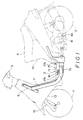
- Fig. 1 is an illustration of a side view of a scooter-type motorcycle to which the present invention is applicable.
- the scooter-type motorcycle is provided with a vehicle body supported by a front wheel 1 and a rear wheel 2, and the central portion of the vehicle body is downwardly frontwardly curved to form a flat floor step portion 3.
- the rear portion of the vehicle body extends upwardly from the rear side of the floor step portion 3 and a seat 4 is disposed to the rear portion.
- a rider of the scooter-type motorcycle sits on the seat 4 with legs being on the floor step portion 3 and hands gripping a handle 5.
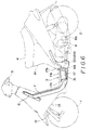
- Fig. 2 shows a part of a frame structure of the scooter-type motorcycle of Fig. 1, in which one down tube 7 connected to a head pipe 6 leads downwardly and then extends rearwardly.
- a unit-swing-type engine unit 8 is pivotally supported by the rear end portion of the down tube 7 as shown in Fig. 1 and a starter motor 8a is disposed for the engine unit 8.
- the down tube 7 is provided with a horizontal portion 7a on both the sides of which are arranged step board base plates 10 through a central attachment plate 9.
- a step board 11, generally made of a synthetic resin material, is applied to the base plates 10 thereby to form the flat floor step portion 3.
- the front portion of the floor step portion 3 is continuous to a leg shield 13 covering the head pipe 6 and a front fork 12, and the rear portion of the floor step portion 3 is continuous to a rear body 14 extending upwardly, on which the seat 4 is rested.
- the step board 11 may be formed as an extension of the leg shield 13.
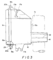
- a battery box 15 is arranged on one side below the step board 11.
- the battery box 15 is formed of a water-proof material, such as synthetic resin or the outer surface of the battery box is subjected to a water-proof treatment.
- the battery box 15 is provided with an opening 15a formed to the outside surface of the battery box 15 and a support arm 16 is integrally formed to the inside surface 15b thereof so as to extend inside.
- Bracket pieces 17a and 17b are formed to the upper end portion of the outside surface and clamp members 18a and 18b are also formed around the opening 15a.
- a cap 19 is applied to the opening 15a and the cap 19 is clamped by the engagement of clamping pieces 20a and 20b formed as flanges to the peripheral edge of the cap 19 with the clamp members 18a and 18b.
- the support arm 16 is mounted on a rearwardly extending portion 7a of the down tube 7 and the bracket pieces 17a and 17b are fastened to bracket pieces 21a and 21b, respectively, formed to the attachment plate 9 and the step board base plates 10, whereby the battery box 15 is fixed. Accordingly, the the battery box 15 is disposed below the step board 11 in a space which is not utilized in the conventional scooter-type motorcycle as dead space.
- a battery and associated electrical equipments such as a starter relay are accommodated in the battery box 15 and hermetically sealed by the cap 19, which is positioned to the transversely outside of the vehicle body. Accordingly, the battery can be easily accommodated into or taken out from the battery box 15 by removing the cap 19 from the outside of the vehicle body.
- the support arm 16 has an upper, as viewed, flat surface and a lower surface on which are formed a plurality of ribs 22 extending substantially perpendicular to the longitudinal axis of the down tube portion 7a so that the lower edges of the ribs 22 abut against the down tube portion 7a.
- a plurality of ribs 23 are formed on the back surface of the step board 11 so as to extend downwardly such that the front ends of the ribs 23 abut against the upper surface of the support arm 16.
- the central portion of the step board 11 is carried by the down tube portion 7a through the support arm 16 to thereby reinforce the step board 11 made of a synthetic resin, for example, and prevent the deflection thereof which may be caused by the weight of the legs rested on the floor step portion 3.
- a rubber made packing 29 may be embedded in the peripheral edge portion of the cap 19 to improve the sealing performance at a time of closing the cap 19.
- the battery box 15 is held below the floor step portion 3 which is per se positioned at the lower portion of the vehicle body, the gravity center of the vehicle body can be set to a lower portion thereof, thus the scooter-type motorcycle being maintained stably and increasing the running stability thereof.
- the battery is accommodated in the battery box 15, so that the battery itself can be protected from the splashing of water or mud.
- the battery can be easily accommodated into and taken out from the battery box 15 from the outer side portion of the vehicle body with ease, thus improving the maintenance performance.
- the support arm 16 is rested to the down tube portion 7a, numbers of the parts or equipments for fixing the support arm to the frame can be reduced as well as for reinforcing the step board 11. Since the battery is arranged near the starter of the engine, harnesses can be shortened and since the starter relay can be accommodated at the same time of the accommodation of the battery, the relay is arranged between a starter motor and the battery, thus improving the motor efficiency and starting performance.
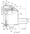
- a battery box 116 according to another embodiment of the present invention is arranged below the floor step portion 3.
- the battery box 116 is provided with an opening 116a formed to the outside surface of the battery box 116 and a support arm 16 is integrally formed with the inside surface 116b thereof so as to extend inside.
- Bracket pieces 17a and 17b are formed to the upper end portion of the outside surface and clamp members 18a and 18b are also formed around the opening 116a.
- the battery box 116 is secured in the manner that the support arm 16 is mounted on the down tube portion 7a and the bracket pieces 17a and 17b are connected to bracket pieces 126a and 126b (Fig. 7) formed to the attachment plate 9 and the step board 11.
- the interior of the battery box 116 is separated into two compartments in the longitudinal direction, in a state shown in Fig. 6, of the vehicle body by a partition plate 127 formed integrally with the body of the battery box 116.
- a battery 117 is accommodated in the front, i.e. front wheel side, compartment and a starter relay 118 is accommodated in the rear, i.e. engine unit or rear wheel side, compartment.
- the front end of the partition plate 127 is formed as a flat projection 127a which is engaged with a hole, not shown, formed to the starter relay 118 to secure the same to the partition plate 127.
- a fuse holder 128 is also disposed on the side surface of the partition plate 127 and integrally with the body of the battery box 116.
- the fuse holder 128 comprises two parts, each in C-shape, facing each other, and a fuse box 120 in which a fuse 119 is accommodated is plugged tightly into the fuse holder 128.
- the battery box 116 of this embodiment is also closed hermetically by a cap 124 and the battery box 116 is also arranged in the vehicle body so that the cap 124 is directed to the transverse side of the vehicle body thereby to make ensure the easy accommodation and take-out of the battery 117, the starter relay 118 and the fuse box 120 together or separately.
- a rubber made packing 29 may be embedded in the peripheral edge portion of the cap 124 to improve the sealing performance at a time of closing the cap 124.
- the following advantageous effects can be achieved. Namely, since the battery, the starter relay and the fuse are compactly assembled in the battery box, the length of wires connecting these electrical equipments can be made short, thus effectively reducing the electric resistance and improving the maintenance performance. The total weight can be also reduced. Moreover, since the battery relatively having a heavy weight is disposed at the lowest portion of the vehicle body, the center of gravity of the vehicle itself is set to a low position, thus improving the running stability of the vehicle.
Landscapes
- Chemical & Material Sciences (AREA)
- Chemical Kinetics & Catalysis (AREA)
- Electrochemistry (AREA)
- General Chemical & Material Sciences (AREA)
- Engineering & Computer Science (AREA)
- Mechanical Engineering (AREA)
- Automatic Cycles, And Cycles In General (AREA)
- Battery Mounting, Suspending (AREA)
Claims (9)
- Dispositif de support de batterie d'un véhicule du type scooter, dans lequel un marchepied (11) est posé sur une boucle inférieure (7, 7a) s'étendant vers le bas et ensuite vers l'arrière depuis un tuyau de tête (6), le marchepied (11) étant disposé des deux côtés de la boucle inférieure (7, 7a), et une partie repose-pieds (3) est formée sur le marchepied (11), sur une partie basse d'un chassis de véhicule, entre une poignée (5) et un siège (4) sur lequel s'assied un conducteur, et un support ou boîtier de batterie (15, 116) servant à loger une batterie (117) est disposé sur le côté de la boucle inférieure (7, 7a) qui est situé au-dessous du marchepied (11),
caractérisé en ce que le support de batterie comprend un boîtier ou support (15, 16) pourvu d'une ouverture (15a, 16a) qui est recouverte par un moyen formant couvercle (19, 24) tourné transversalement vers l'extérieur du chassis de véhicule, et le support de batterie (15) est également pourvu d'un bras de support (16) s'étendant vers l'intérieur, vers la boucle inférieure (7, 7a), le bras de support (16) présente une partie inférieure (22) qui vient en butée contre la boucle inférieure (7, 7a) et le bras de support (16) est également pourvu d'une partie supérieure plane, de manière à supporter la partie centrale inférieure (23) du marchepied (11). - Dispositif de support de batterie selon la revendication 1, dans lequel la partie inférieure du bras de support (16) est pourvue d'une pluralité de nervures (22) s'étendant dans une direction comprise dans un plan pratiquement perpendiculaire à l'axe longitudinal de la boucle inférieure (7a).
- Dispositif de support de batterie selon la revendication 1 ou 2, dans lequel la pluralité de nervures (22) est formée sur la partie centrale inférieure du marchepied (11), de manière que les extrémités s'étendant vers le bas des nervures (23) viennent en butée contre la partie supérieure plane du bras de support (16).
- Dispositif de support de batterie selon la revendication 1, dans lequel le boîtier de batterie (15, 15) est soumis à un traitement d'étanchement à l'eau.
- Dispositif de support de batterie selon la revendication 1, dans lequel le moyen formant couvercle (19) est pourvu d'une garniture (29) servant à sceller hermétiquement l'ouverture (15a) du boîtier de batterie.
- Dispositif de support de batterie selon la revendication 1, dans lequel un équipement électrique (118-120, 128) est disposé dans le boîtier de batterie (116), conjointement avec la batterie (117).
- Dispositif de support de batterie selon la revendication 6, dans lequel l'équipement électrique (118-120, 128) est un relais de démarreur (118).
- Dispositif de support de batterie selon la revendication 1, dans lequel le boîtier de batterie (116) est divisé en deux compartiments, l'un étant destiné à loger la batterie (117) et un autre à loger une pluralité d'équipements électriques (128, 119), au moyen d'une plaque de séparation (127) formée d'un seul tenant avec une paroi intérieure du boîtier de batterie (116).
- Dispositif de support de batterie selon la revendication 8, dans lequel les équipements électriques (118-120, 128) sont un relais de démarreur (118) et des moyens fusibles (119, 120, 128) et dans lequel le relais de démarreur (118) est fixé à la plaque de séparation (127) et le moyen fusible (119-120, 128) comprend un support de fusible (128) réalisé d'un seul tenant avec le boîtier de batterie (116) et un fusible (119, 120) destiné à être enfiché dans le support de fusible (128).
Applications Claiming Priority (4)
| Application Number | Priority Date | Filing Date | Title |
|---|---|---|---|
| JP53099/90 | 1990-05-23 | ||
| JP5309990U JPH0810551Y2 (ja) | 1990-05-23 | 1990-05-23 | スクータ型車両のバッテリ保持装置 |
| JP1990112057U JP2538698Y2 (ja) | 1990-10-29 | 1990-10-29 | スクータ型車両のバッテリ保持装置 |
| JP112057/90 | 1990-10-29 |
Publications (2)
| Publication Number | Publication Date |
|---|---|
| EP0459286A1 EP0459286A1 (fr) | 1991-12-04 |
| EP0459286B1 true EP0459286B1 (fr) | 1994-11-23 |
Family
ID=26393808
Family Applications (1)
| Application Number | Title | Priority Date | Filing Date |
|---|---|---|---|
| EP91108254A Expired - Lifetime EP0459286B1 (fr) | 1990-05-23 | 1991-05-22 | Dispositif de support de batterie pour véhicule du type scooter |
Country Status (4)
| Country | Link |
|---|---|
| EP (1) | EP0459286B1 (fr) |
| KR (1) | KR910019847A (fr) |
| DE (1) | DE69105237T2 (fr) |
| ES (1) | ES2064003T3 (fr) |
Cited By (1)
| Publication number | Priority date | Publication date | Assignee | Title |
|---|---|---|---|---|
| CN100473578C (zh) * | 2004-11-25 | 2009-04-01 | 光阳工业股份有限公司 | 摩托车 |
Families Citing this family (8)
| Publication number | Priority date | Publication date | Assignee | Title |
|---|---|---|---|---|
| JP2981963B2 (ja) * | 1993-08-31 | 1999-11-22 | 本田技研工業株式会社 | 自動二・三輪車におけるバッテリ配置構造 |
| JP3526628B2 (ja) * | 1994-07-25 | 2004-05-17 | 本田技研工業株式会社 | スクータの電装品取付構造 |
| JP3674879B2 (ja) * | 1995-09-11 | 2005-07-27 | 本田技研工業株式会社 | スクータ型自動二輪車用バッテリ取付装置 |
| FR2859684B1 (fr) * | 2003-09-16 | 2006-03-17 | Peugeot Motocycles | Vehicule de type scooter |
| JP2006142874A (ja) | 2004-11-16 | 2006-06-08 | Yamaha Motor Co Ltd | 鞍乗型車両、及び、ランプ取付方法 |
| JP2006182124A (ja) | 2004-12-27 | 2006-07-13 | Yamaha Motor Co Ltd | 自動二輪車 |
| JP2006182269A (ja) * | 2004-12-28 | 2006-07-13 | Yamaha Motor Co Ltd | 自動二輪車 |
| WO2013144975A2 (fr) * | 2012-03-29 | 2013-10-03 | Tvs Motor Company Limited | Système de démarrage électrique pour un véhicule à moteur à combustion interne |
Family Cites Families (2)
| Publication number | Priority date | Publication date | Assignee | Title |
|---|---|---|---|---|
| JPS5950885A (ja) * | 1982-09-14 | 1984-03-24 | 本田技研工業株式会社 | 自動二輪車 |
| GB2183081A (en) * | 1985-11-19 | 1987-05-28 | John Malcolm Bradley | Battery case |
-
1991
- 1991-05-22 DE DE69105237T patent/DE69105237T2/de not_active Expired - Fee Related
- 1991-05-22 ES ES91108254T patent/ES2064003T3/es not_active Expired - Lifetime
- 1991-05-22 EP EP91108254A patent/EP0459286B1/fr not_active Expired - Lifetime
- 1991-05-22 KR KR1019910008270A patent/KR910019847A/ko not_active Application Discontinuation
Cited By (1)
| Publication number | Priority date | Publication date | Assignee | Title |
|---|---|---|---|---|
| CN100473578C (zh) * | 2004-11-25 | 2009-04-01 | 光阳工业股份有限公司 | 摩托车 |
Also Published As
| Publication number | Publication date |
|---|---|
| EP0459286A1 (fr) | 1991-12-04 |
| DE69105237D1 (de) | 1995-01-05 |
| ES2064003T3 (es) | 1995-01-16 |
| KR910019847A (ko) | 1991-12-19 |
| DE69105237T2 (de) | 1995-04-06 |
Similar Documents
| Publication | Publication Date | Title |
|---|---|---|
| KR101479434B1 (ko) | 전동 차량 구동 장치 | |
| JP5417104B2 (ja) | 鞍乗り型車両のバッテリ周辺構造 | |
| US6647121B2 (en) | Motorcycle audio system | |
| JP5938249B2 (ja) | 電動式鞍乗り型車両のバッテリユニット | |
| EP0459286B1 (fr) | Dispositif de support de batterie pour véhicule du type scooter | |
| KR100472329B1 (ko) | 자동 이륜차의 시트 록 장치 및 그래브 레일의 부착 구조 | |
| JP3691771B2 (ja) | 電動自転車 | |
| JP3272542B2 (ja) | 自動二輪車の部品取付構造 | |
| JPH08225091A (ja) | 自動二,三輪車の補機類取付構造 | |
| JPWO2004078568A1 (ja) | 鞍乗型車両 | |
| US8960351B1 (en) | Utility vehicle | |
| JP3526628B2 (ja) | スクータの電装品取付構造 | |
| JP2915651B2 (ja) | 自動二輪車のバッテリ配置構造 | |
| KR100573856B1 (ko) | 자동이륜차에 있어서의 전기부품 배치구조 | |
| JP2006182269A (ja) | 自動二輪車 | |
| JP3999528B2 (ja) | 自動二輪車 | |
| EP3689724B1 (fr) | Véhicule hybride | |
| JPH0592782A (ja) | 自動二輪車のバツテリ収納箱 | |
| KR960004436Y1 (ko) | 스쿠터형 차량의 밧데리 지지장치 | |
| JP2022083187A (ja) | バッテリ | |
| JP3367760B2 (ja) | 車両の車体構造 | |
| JPH0672378A (ja) | 電動式スクータ型車両 | |
| JPS6324076Y2 (fr) | ||
| CN217048901U (zh) | 踏板式电动车 | |
| EP4012827A1 (fr) | Batterie |
Legal Events
| Date | Code | Title | Description |
|---|---|---|---|
| PUAI | Public reference made under article 153(3) epc to a published international application that has entered the european phase |
Free format text: ORIGINAL CODE: 0009012 |
|
| 17P | Request for examination filed |
Effective date: 19910522 |
|
| AK | Designated contracting states |
Kind code of ref document: A1 Designated state(s): DE ES FR IT |
|
| 17Q | First examination report despatched |
Effective date: 19930827 |
|
| GRAA | (expected) grant |
Free format text: ORIGINAL CODE: 0009210 |
|
| AK | Designated contracting states |
Kind code of ref document: B1 Designated state(s): DE ES FR IT |
|
| REF | Corresponds to: |
Ref document number: 69105237 Country of ref document: DE Date of ref document: 19950105 |
|
| REG | Reference to a national code |
Ref country code: ES Ref legal event code: FG2A Ref document number: 2064003 Country of ref document: ES Kind code of ref document: T3 |
|
| ET | Fr: translation filed | ||
| ITF | It: translation for a ep patent filed | ||
| PLBE | No opposition filed within time limit |
Free format text: ORIGINAL CODE: 0009261 |
|
| STAA | Information on the status of an ep patent application or granted ep patent |
Free format text: STATUS: NO OPPOSITION FILED WITHIN TIME LIMIT |
|
| 26N | No opposition filed | ||
| PGFP | Annual fee paid to national office [announced via postgrant information from national office to epo] |
Ref country code: FR Payment date: 20040510 Year of fee payment: 14 |
|
| PGFP | Annual fee paid to national office [announced via postgrant information from national office to epo] |
Ref country code: ES Payment date: 20040518 Year of fee payment: 14 |
|
| PGFP | Annual fee paid to national office [announced via postgrant information from national office to epo] |
Ref country code: DE Payment date: 20040603 Year of fee payment: 14 |
|
| PG25 | Lapsed in a contracting state [announced via postgrant information from national office to epo] |
Ref country code: IT Free format text: LAPSE BECAUSE OF NON-PAYMENT OF DUE FEES;WARNING: LAPSES OF ITALIAN PATENTS WITH EFFECTIVE DATE BEFORE 2007 MAY HAVE OCCURRED AT ANY TIME BEFORE 2007. THE CORRECT EFFECTIVE DATE MAY BE DIFFERENT FROM THE ONE RECORDED. Effective date: 20050522 |
|
| PG25 | Lapsed in a contracting state [announced via postgrant information from national office to epo] |
Ref country code: ES Free format text: LAPSE BECAUSE OF NON-PAYMENT OF DUE FEES Effective date: 20050523 |
|
| PG25 | Lapsed in a contracting state [announced via postgrant information from national office to epo] |
Ref country code: DE Free format text: LAPSE BECAUSE OF NON-PAYMENT OF DUE FEES Effective date: 20051201 |
|
| PG25 | Lapsed in a contracting state [announced via postgrant information from national office to epo] |
Ref country code: FR Free format text: LAPSE BECAUSE OF NON-PAYMENT OF DUE FEES Effective date: 20060131 |
|
| REG | Reference to a national code |
Ref country code: FR Ref legal event code: ST Effective date: 20060131 |
|
| REG | Reference to a national code |
Ref country code: ES Ref legal event code: FD2A Effective date: 20050523 |