EP0458705B1 - Heater unit structure of air mixing apparatus for automotive vehicle - Google Patents
Heater unit structure of air mixing apparatus for automotive vehicle Download PDFInfo
- Publication number
- EP0458705B1 EP0458705B1 EP91401346A EP91401346A EP0458705B1 EP 0458705 B1 EP0458705 B1 EP 0458705B1 EP 91401346 A EP91401346 A EP 91401346A EP 91401346 A EP91401346 A EP 91401346A EP 0458705 B1 EP0458705 B1 EP 0458705B1
- Authority
- EP
- European Patent Office
- Prior art keywords
- duct
- instrument panel
- vent duct
- defroster
- heater unit
- Prior art date
- Legal status (The legal status is an assumption and is not a legal conclusion. Google has not performed a legal analysis and makes no representation as to the accuracy of the status listed.)
- Expired - Lifetime
Links
Images


Classifications
-
- B—PERFORMING OPERATIONS; TRANSPORTING
- B60—VEHICLES IN GENERAL
- B60H—ARRANGEMENTS OF HEATING, COOLING, VENTILATING OR OTHER AIR-TREATING DEVICES SPECIALLY ADAPTED FOR PASSENGER OR GOODS SPACES OF VEHICLES
- B60H1/00—Heating, cooling or ventilating [HVAC] devices
- B60H1/00007—Combined heating, ventilating, or cooling devices
- B60H1/00021—Air flow details of HVAC devices
- B60H1/00028—Constructional lay-out of the devices in the vehicle
Definitions
- the present invention relates to a heater unit structure arrangement for an air mixing apparatus for an automotive vehicule, such as disclosed in the general part of the generic claim.
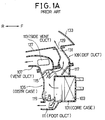
- FIG. 1A A conventional heater unit structure arrangement of this kind is shown on figure 1A.
- This heater unit structure arrangement includes a core case 101 having a heating heat exchanger 103 (e.g. heater core), and an air distribution case 105 connectable to a vent duct 107, a defroster duct 109, and a foot duct 111, respectively.
- a heating heat exchanger 103 e.g. heater core
- an air distribution case 105 connectable to a vent duct 107, a defroster duct 109, and a foot duct 111, respectively.
- Two side vent ducts 113 extending between the driver seat side and the front passenger seat side are usually formed integral with the vent duct 107.
- the assembly procedure is as follows : the heater unit is fixed to the vehicle body ; the respective ducts 107, 109 and 111 are attached to the distribution case 105 ; the instrument panel 127 is fixed to the vehicle body ; and the defroster ducts 109 are finally attached to opening portions 129 of the instrument panel 127.
- the assembly work can be completed by attaching the respective ducts 107, 109, and 111 to the distribution case 105 before attaching the instrument panel 127, there exists a problem in that it takes much time to attach each duct one by one to the distribution case 105 and therefore the assembly productivity is extremely low.
- the instrument panel 127 is large in size and therefore easily deformable in shape, a troublesome assembly work is required to fit a blowing outlet 131 of the defroster duct 109 (for blowing out air toward the windshield 133) to the opening portion 129 of the instrument panel 127.
- the heater unit structure arrangement proposed by the invention comprises the features which are set forth in the characterizing part of the generic claim.
- the method for establishing the heater unit structure arrangement according to claim 1 includes the features which are set forth in the characterizing part of claim 2.
- the guide duct connectable to a side vent duct formed into a complicated shape and extending to the driver seat side is formed integral with the distribution case and therefore the complicated-shape side vent duct is connected to the distribution case via the guide duct, it is possible to previously attach the vent duct extending to the front passenger seat side and the defroster ducts to the instrument panel, so that workability of various duct asembly can be improved markedly.
- the vent duct and the defroster ducts can be previously and securely connected to the instrument panel, it is possible to prevent air leakage through the connecting portions between the two.
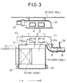
- Fig. 2 is an air mixing apparatus for an automotive vehicle, which comprises a blower unit 1, a cooling unit 3, and a heater unit 5.
- the blower unit 1 is provided with a motor fan (not shown), an outside air introducing port 7 for introducing outside air into the vehicle room by the motor fan, and an inside air introducing port 9 for introducing vehicle inside air thereinto by the motor fan.
- the respective ports 7 and 9 can be closed or opened by a pivotal flapper 11 actuated in response to a change-over mode switch (not shown).
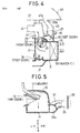
- the heater unit 5 is formed with a core case 15 for housing a heater core 13 and a distribution case 17 communicating with the core case 15, as shown in Fig. 4.
- An air mix door 19 (shown in Fig. 5) is disposed on the upstream side of the heater core 13 through which coolant of an engine (not shown) is passed.
- the coolant temperature increases with increasing engine temperature.
- the distribution case 17 is formed with first and second upper duct connecting ports 25 and 27 connectable to a side vent duct 21 extending to the front passenger seat side and two defroster ducts 23, respectively on the upper surface thereof. Further, the distribution case 17 is formed with a third duct connecting port 31 connectable to a bifurcated rear duct 29 and a foot blowing port 33, on the lower part thereof. Therefore, when a defroster door 30, a door 32 and a foot door 34 are pivoted from the respective solid line positions to the dot-dot-dashed line positions or vice versa in Fig. 4, it is possible to control the amount of air passed through the respective ducts 23, 21 and 29, in various combination modes.
- the air mix door 19 can be controllably pivoted in response to signals from an inside-outside temperature selecting switch; and the defroster door 30, the vent door 32 and the foot door 34 can be controllably provided in response to signals from a blower port selecting switch.
- the distribution case 17 is formed with a guide duct 37 connectable to a side vent duct 35 extending to a driver seat side and fixed to the vehicle body.
- the guide duct 37 is formed into a curved shape extending from the upper opening 37a to the lower side thereof so as to be connectable to the side vent duct 35.
- the vent duct 21 is formed with two center vent blowing outlets 41 and a connecting port 45 connected to a side vent duct 43 extending to the front passenger seat (the leftward side in Fig. 2).
- the vent duct 21 and the side vent duct 43 and further the defroster ducts 23 are all previously attached to the inside surface of the instrument panel 47 with respective brackets 21a, 23a, and 43a, respectively.
- each blowing outlet 23b of each defroster duct 23 is securely located and connected to the opening 47a of the instrument panel 47 as shown in Fig, 4.
- 49 denotes a front windshield and 51 denotes a sealing urethane sandwiched between the distributing case 17 and the defroster duct 23.
- the assembling procedure is as follows: the heater unit 5 is fixed to the vehicle body; the side vent duct 35 on the driver seat side is connected to the guide duct 37 of the distributing case 17 and fixed to the vehicle body; the vent duct 21 and the two defroster ducts 23 are previously connected to the instrument panel 47; the instrument panel 47 is temporality mounted on the vehicle body; the vent duct 21 and the two defroster ducts 23 connected to the instrument panel 47 is fitted from above to the first and second duct connecting ports 25 and 27 of the distributing case 17, and the instrument panel 47 is fixed to the vehicle body. Therefore, it is possible to simultaneously connect the side vent duct 43 and the vent duct 21 and the two defroster ducts 23 to the heater unit 5 simultaneously when the instrument panel 47 is fixed to the vehicle body.
- the distributing case 17 is formed with the curved guide duct 37 connectable to the driver-side vent duct, it is possible to previously attach the passenger-side vent duct and the defroster ducts to the instrument panel, thus it being possible to markedly improve the workability of the duct assembly.
- blowing outlets of the defroster ducts can be previously and securely attached to the instrument panel, it is possible to effectively blow out air without leakage through the connection portions of the blowing outlets.
Landscapes
- Physics & Mathematics (AREA)
- Thermal Sciences (AREA)
- Engineering & Computer Science (AREA)
- Mechanical Engineering (AREA)
- Air-Conditioning For Vehicles (AREA)
Applications Claiming Priority (2)
| Application Number | Priority Date | Filing Date | Title |
|---|---|---|---|
| JP133986/90 | 1990-05-25 | ||
| JP2133986A JP2566044B2 (ja) | 1990-05-25 | 1990-05-25 | 車両用空気調和装置のヒータユニット構造 |
Publications (3)
| Publication Number | Publication Date |
|---|---|
| EP0458705A2 EP0458705A2 (en) | 1991-11-27 |
| EP0458705A3 EP0458705A3 (en) | 1992-05-27 |
| EP0458705B1 true EP0458705B1 (en) | 1995-02-08 |
Family
ID=15117715
Family Applications (1)
| Application Number | Title | Priority Date | Filing Date |
|---|---|---|---|
| EP91401346A Expired - Lifetime EP0458705B1 (en) | 1990-05-25 | 1991-05-24 | Heater unit structure of air mixing apparatus for automotive vehicle |
Country Status (4)
| Country | Link |
|---|---|
| US (1) | US5217405A (ja) |
| EP (1) | EP0458705B1 (ja) |
| JP (1) | JP2566044B2 (ja) |
| DE (1) | DE69107239T2 (ja) |
Cited By (1)
| Publication number | Priority date | Publication date | Assignee | Title |
|---|---|---|---|---|
| US8944144B2 (en) | 2003-03-13 | 2015-02-03 | Valeo Systemes Thermiques | Heating and ventilation and/or air conditioning device with a compact construction for a motor vehicle passenger compartment |
Families Citing this family (28)
| Publication number | Priority date | Publication date | Assignee | Title |
|---|---|---|---|---|
| US6352862B1 (en) * | 1989-02-17 | 2002-03-05 | Unilever Patent Holdings B.V. | Analytical test device for imuno assays and methods of using same |
| US5335718A (en) * | 1992-04-02 | 1994-08-09 | Ford Motor Company | Space-efficient air conditioning/heating module |
| FR2700502B1 (fr) * | 1993-01-19 | 1995-02-17 | Renault | Dispositif distributeur d'air d'une installation de chauffage et de climatisation de véhicule automobile. |
| ES2081678T3 (es) * | 1993-12-20 | 1996-03-16 | Siemens Ag | Aparato acondicionador de aire o calefactor, en especial para ser instalado en un automovil. |
| JP3672586B2 (ja) | 1994-03-24 | 2005-07-20 | 株式会社半導体エネルギー研究所 | 補正システムおよびその動作方法 |
| FR2735426B1 (fr) * | 1995-06-14 | 1997-07-18 | Valeo Climatisation | Dispositif de chauffage-ventilation et/ou de climatisation de l'habitacle d'un vehicule automobile |
| US5673964A (en) * | 1995-08-04 | 1997-10-07 | Ford Motor Company | Integral center-mounted airhandling system with integral instrument panel air-conditioning duct and structural beam |
| DE59707343D1 (de) | 1996-01-27 | 2002-07-04 | Volkswagen Ag | Luftkanalanordnung zur Fondbelüftung und/oder -Heizung eines Kraftfahrzeuges |
| US5988263A (en) * | 1997-07-08 | 1999-11-23 | Valeo Climate Control, Inc. | Mixing device for air conditioning system |
| DE19751652A1 (de) * | 1997-11-21 | 1999-05-27 | Behr Gmbh & Co | Heizungs- und/oder Klimaanlage für ein Fahrzeug, insbesondere für einen Personenkraftwagen |
| DE19839520C1 (de) * | 1998-08-29 | 2000-02-17 | Daimler Chrysler Ag | Klimaanlage |
| US6186885B1 (en) * | 1999-02-18 | 2001-02-13 | Ford Motor Company | Integrated HVAC system for an automotive vehicle |
| IT1308375B1 (it) * | 1999-02-19 | 2001-12-17 | Magneti Marelli Spa | Gruppo di scambio termico preassemblato e veicolo munito di talegruppo. |
| JP2001209358A (ja) | 2000-01-26 | 2001-08-03 | Seiko Epson Corp | 表示画像のムラ補正 |
| WO2001068392A1 (fr) * | 2000-03-13 | 2001-09-20 | Zexel Valeo Climate Control Corporation | Systeme de climatisation d'automobile |
| DE10112969B4 (de) * | 2001-03-14 | 2009-07-30 | Behr Gmbh & Co. Kg | Klimaanlage für ein Kraftfahrzeug |
| US6769978B2 (en) | 2001-12-21 | 2004-08-03 | Modine Manufacturing Company | Method and apparatus for controlling airflow in a vehicular HVAC system |
| KR100482594B1 (ko) * | 2003-04-14 | 2005-04-14 | 현대자동차주식회사 | 차량의 성에 제거 장치 |
| US6942564B1 (en) * | 2004-02-27 | 2005-09-13 | Denso International America, Inc. | Passenger foot duct |
| DE102004015270A1 (de) * | 2004-03-29 | 2005-10-20 | Valeo Klimasysteme Gmbh | Luftbehandlungsanlagengehäusestruktur |
| DE102004024069A1 (de) * | 2004-05-13 | 2005-12-08 | Behr Gmbh & Co. Kg | System zur Kraftfahrzeug-Belüftung und/oder -Temperierung |
| WO2006000434A1 (de) * | 2004-06-24 | 2006-01-05 | Behr Gmbh & Co. Kg | Klimaanlage, insbesondere kraftfahrzeug-klimaanlage |
| PL1634735T3 (pl) * | 2004-09-10 | 2008-06-30 | Behr France Rouffach Sas | Modułowy klimatyzator samochodowy |
| JP4814676B2 (ja) * | 2006-03-31 | 2011-11-16 | 株式会社 日立ディスプレイズ | 自発光型表示装置 |
| US9851114B2 (en) * | 2011-02-15 | 2017-12-26 | Trane International Inc. | HVAC system with multipurpose cabinet for auxiliary heat transfer components |
| US10377347B2 (en) * | 2015-03-09 | 2019-08-13 | Ford Global Technologies, Llc | Low-profile ventilation system for a motor vehicle and related method of providing a low-profile ventilation system |
| DE102015112379A1 (de) * | 2015-07-29 | 2017-02-02 | Halla Visteon Climate Control Corp. | Kompakte Wärmeübertrager-Gebläse-Einheit für Kraftfahrzeuge |
| US10787154B2 (en) | 2016-09-07 | 2020-09-29 | Ford Global Technologies, Llc | Windshield defroster with secondary ducted outlet |
Family Cites Families (8)
| Publication number | Priority date | Publication date | Assignee | Title |
|---|---|---|---|---|
| US2787888A (en) * | 1953-12-18 | 1957-04-09 | Gen Motors Corp | Air conditioning systems |
| JPS5844013Y2 (ja) * | 1979-11-17 | 1983-10-05 | 株式会社ボッシュオートモーティブ システム | 自動車用空調装置のヒ−タユニツト |
| JPS60209318A (ja) * | 1984-04-04 | 1985-10-21 | Nissan Motor Co Ltd | 自動車用空気調和装置のヒ−タユニツト |
| JPS6115618U (ja) * | 1984-07-04 | 1986-01-29 | 日産自動車株式会社 | 空調装置 |
| JPH0755615B2 (ja) * | 1986-06-04 | 1995-06-14 | 日本電装株式会社 | 車両用空気調和装置 |
| JPH085306B2 (ja) * | 1986-12-27 | 1996-01-24 | 日本電装株式会社 | 車両用空気調和装置 |
| FR2615148B1 (fr) * | 1987-05-12 | 1992-03-27 | Valeo | Corps d'appareil rigide pour installation de chauffage de vehicule automobile |
| JPH0723290Y2 (ja) * | 1987-09-08 | 1995-05-31 | 日野自動車工業株式会社 | 自動車暖房装置のヒータケーシング |
-
1990
- 1990-05-25 JP JP2133986A patent/JP2566044B2/ja not_active Expired - Fee Related
-
1991
- 1991-05-23 US US07/704,433 patent/US5217405A/en not_active Expired - Lifetime
- 1991-05-24 EP EP91401346A patent/EP0458705B1/en not_active Expired - Lifetime
- 1991-05-24 DE DE69107239T patent/DE69107239T2/de not_active Expired - Fee Related
Cited By (1)
| Publication number | Priority date | Publication date | Assignee | Title |
|---|---|---|---|---|
| US8944144B2 (en) | 2003-03-13 | 2015-02-03 | Valeo Systemes Thermiques | Heating and ventilation and/or air conditioning device with a compact construction for a motor vehicle passenger compartment |
Also Published As
| Publication number | Publication date |
|---|---|
| JP2566044B2 (ja) | 1996-12-25 |
| DE69107239D1 (de) | 1995-03-23 |
| JPH0431120A (ja) | 1992-02-03 |
| EP0458705A2 (en) | 1991-11-27 |
| EP0458705A3 (en) | 1992-05-27 |
| DE69107239T2 (de) | 1995-10-05 |
| US5217405A (en) | 1993-06-08 |
Similar Documents
| Publication | Publication Date | Title |
|---|---|---|
| EP0458705B1 (en) | Heater unit structure of air mixing apparatus for automotive vehicle | |
| US5101883A (en) | Method of assembly of single and multi-zone vehicle heating and a/c systems | |
| JP3931818B2 (ja) | 車両用空調装置 | |
| JP2000238523A (ja) | 自動車用一体型hvacシステム | |
| WO2001068392A1 (fr) | Systeme de climatisation d'automobile | |
| GB2065866A (en) | Air conditioner for automobile | |
| US6675598B2 (en) | Vehicle air conditioner with arrangement structure of face ducts | |
| EP1284882B1 (en) | Dashboard assembly | |
| US20020068521A1 (en) | Vehicle air conditioner and mounting structure | |
| JP3877191B2 (ja) | 車両用空調ユニットを含むユニットアセンブリ | |
| JPH11208241A (ja) | 自動車用空気調和装置 | |
| JP2000190755A (ja) | インストルメントパネル | |
| JP2002079820A (ja) | 自動車用空調装置 | |
| JP3294659B2 (ja) | 車両用空調装置 | |
| JPH0712110Y2 (ja) | 自動車の空調装置 | |
| JP4040342B2 (ja) | インストルメントパネル | |
| JP4186624B2 (ja) | 車両用空調装置 | |
| JPH0751930Y2 (ja) | トラック用空気調和装置 | |
| JP3414884B2 (ja) | 車両用空調ユニットとダクトとの接続構造 | |
| JP2001010329A (ja) | 車両用空調装置 | |
| JP2002178794A (ja) | インストルメントパネル構造 | |
| JP3873810B2 (ja) | 車両用ダクト構造 | |
| JP3617147B2 (ja) | 車両の空調操作装置 | |
| JPH0748411Y2 (ja) | 車両用デフロスタダクト構造 | |
| JP2002036851A (ja) | 空調装置の車両搭載構造および車両搭載方法 |
Legal Events
| Date | Code | Title | Description |
|---|---|---|---|
| PUAI | Public reference made under article 153(3) epc to a published international application that has entered the european phase |
Free format text: ORIGINAL CODE: 0009012 |
|
| 17P | Request for examination filed |
Effective date: 19910617 |
|
| AK | Designated contracting states |
Kind code of ref document: A2 Designated state(s): DE FR GB |
|
| PUAL | Search report despatched |
Free format text: ORIGINAL CODE: 0009013 |
|
| AK | Designated contracting states |
Kind code of ref document: A3 Designated state(s): DE FR GB |
|
| 17Q | First examination report despatched |
Effective date: 19930906 |
|
| RBV | Designated contracting states (corrected) |
Designated state(s): DE GB |
|
| GRAA | (expected) grant |
Free format text: ORIGINAL CODE: 0009210 |
|
| AK | Designated contracting states |
Kind code of ref document: B1 Designated state(s): DE GB |
|
| REF | Corresponds to: |
Ref document number: 69107239 Country of ref document: DE Date of ref document: 19950323 |
|
| PLBE | No opposition filed within time limit |
Free format text: ORIGINAL CODE: 0009261 |
|
| STAA | Information on the status of an ep patent application or granted ep patent |
Free format text: STATUS: NO OPPOSITION FILED WITHIN TIME LIMIT |
|
| 26N | No opposition filed | ||
| REG | Reference to a national code |
Ref country code: GB Ref legal event code: IF02 |
|
| PGFP | Annual fee paid to national office [announced via postgrant information from national office to epo] |
Ref country code: DE Payment date: 20070517 Year of fee payment: 17 |
|
| PGFP | Annual fee paid to national office [announced via postgrant information from national office to epo] |
Ref country code: GB Payment date: 20070523 Year of fee payment: 17 |
|
| GBPC | Gb: european patent ceased through non-payment of renewal fee |
Effective date: 20080524 |
|
| PG25 | Lapsed in a contracting state [announced via postgrant information from national office to epo] |
Ref country code: DE Free format text: LAPSE BECAUSE OF NON-PAYMENT OF DUE FEES Effective date: 20081202 |
|
| PG25 | Lapsed in a contracting state [announced via postgrant information from national office to epo] |
Ref country code: GB Free format text: LAPSE BECAUSE OF NON-PAYMENT OF DUE FEES Effective date: 20080524 |