EP0458021A1 - Entrepôt avec rayonnages pour matériel recueilli dans des cassettes autoporteuses - Google Patents
Entrepôt avec rayonnages pour matériel recueilli dans des cassettes autoporteuses Download PDFInfo
- Publication number
- EP0458021A1 EP0458021A1 EP91103573A EP91103573A EP0458021A1 EP 0458021 A1 EP0458021 A1 EP 0458021A1 EP 91103573 A EP91103573 A EP 91103573A EP 91103573 A EP91103573 A EP 91103573A EP 0458021 A1 EP0458021 A1 EP 0458021A1
- Authority
- EP
- European Patent Office
- Prior art keywords
- cassettes
- cassette
- receiving
- transport carriage
- trolley
- Prior art date
- Legal status (The legal status is an assumption and is not a legal conclusion. Google has not performed a legal analysis and makes no representation as to the accuracy of the status listed.)
- Granted
Links
Images


Classifications
-
- B—PERFORMING OPERATIONS; TRANSPORTING
- B65—CONVEYING; PACKING; STORING; HANDLING THIN OR FILAMENTARY MATERIAL
- B65G—TRANSPORT OR STORAGE DEVICES, e.g. CONVEYORS FOR LOADING OR TIPPING, SHOP CONVEYOR SYSTEMS OR PNEUMATIC TUBE CONVEYORS
- B65G1/00—Storing articles, individually or in orderly arrangement, in warehouses or magazines
- B65G1/02—Storage devices
- B65G1/04—Storage devices mechanical
- B65G1/0442—Storage devices mechanical for elongated articles
-
- B—PERFORMING OPERATIONS; TRANSPORTING
- B65—CONVEYING; PACKING; STORING; HANDLING THIN OR FILAMENTARY MATERIAL
- B65G—TRANSPORT OR STORAGE DEVICES, e.g. CONVEYORS FOR LOADING OR TIPPING, SHOP CONVEYOR SYSTEMS OR PNEUMATIC TUBE CONVEYORS
- B65G1/00—Storing articles, individually or in orderly arrangement, in warehouses or magazines
- B65G1/02—Storage devices
- B65G1/04—Storage devices mechanical
- B65G1/0471—Storage devices mechanical with access from beneath
-
- B—PERFORMING OPERATIONS; TRANSPORTING
- B65—CONVEYING; PACKING; STORING; HANDLING THIN OR FILAMENTARY MATERIAL
- B65G—TRANSPORT OR STORAGE DEVICES, e.g. CONVEYORS FOR LOADING OR TIPPING, SHOP CONVEYOR SYSTEMS OR PNEUMATIC TUBE CONVEYORS
- B65G1/00—Storing articles, individually or in orderly arrangement, in warehouses or magazines
- B65G1/02—Storage devices
- B65G1/04—Storage devices mechanical
- B65G1/137—Storage devices mechanical with arrangements or automatic control means for selecting which articles are to be removed
- B65G1/1373—Storage devices mechanical with arrangements or automatic control means for selecting which articles are to be removed for fulfilling orders in warehouses
- B65G1/1378—Storage devices mechanical with arrangements or automatic control means for selecting which articles are to be removed for fulfilling orders in warehouses the orders being assembled on fixed commissioning areas remote from the storage areas
Definitions
- the invention relates to a shelf storage for self-supporting cassettes, rod-shaped or plate-shaped material with a plurality of racks arranged in alignment transversely to the longitudinal direction of the material and separated from one another by shelf aisles, fastened one above the other on vertical shelf supports, extending horizontally across the longitudinal direction of the material into the adjacent shelf aisle
- a storage and retrieval device which can be moved transversely to the longitudinal direction of the material above or to the side of the shelves, through which the supports of the cassettes can be gripped on the front and the cassettes transversely to the Shelf aisles and can be moved up and down in them
- a transport trolley which can be moved longitudinally below the lowest shelf compartments transversely to the material and has at least two receiving spaces arranged next to one another for the cassettes, and finally with at least one station arranged outside the shelves in the direction of travel of the trolley and accessible by the trolley with the cassettes for
- Such a device is the subject of the older German patent application P 39 22 964.5, which, in an improvement to the subject of DE-OS 37 08 401, specifies a possibility, such as the change between a cassette to be stored in the rack storage on the one hand and a cassette to be subsequently removed from the storage rack on the other can be done faster.
- the cassettes on the transport trolley can be moved by appropriate means while it is traveling between the removal station and the racking warehouse, so that at a single meeting point between the transport trolley and the storage and retrieval unit, the next cassette can be placed on the transport trolley and the returned cassette can be removed from the transport trolley, in order to then be brought to the place within the rack warehouse from which the cassette to be subsequently removed from the rack warehouse was removed.
- the station for storing and retrieving or for further processing of the material contained in the cassettes is arranged in the longitudinal direction of the material next to the rack warehouse, so that the cassettes from the trolley in the longitudinal direction of the material, for example, with the help a roller conveyor can be moved out to this station.
- the shelf storage should have several blocks lying closely next to one another in the longitudinal direction of the material, the possibility exists for such a station only for an outer row of shelves, while for the other rows of shelves, the cassettes can only be extended via the end faces of the rows of shelves lying transversely to the material longitudinal direction .
- the older German patent application mentioned contains a simple, front-side removal location, which, however, only enables the handling of a cassette, for example for refilling with new material. With such a swap space, however, the storage and retrieval of the material takes a relatively long time and is cumbersome.
- the object of the invention is therefore to provide a front-end station for storing and retrieving material contained in self-supporting cassettes, which in connection with the transport trolley described allows a quick change between at least two cassettes and possibly also offers the possibility that an operator without Problems - possibly with the help of a buffer zone - has stored several cassettes in front of them and picked or stored them can. All in all, the invention is intended to design the end station for storing and retrieving in such a way that the function and mode of operation of the transport carriage can be maintained and the seasons and the performance of the entire rack warehouse are not restricted by this station.
- the station for storage and retrieval has two stacking storage levels for the cassettes, the lower storage level corresponding to the first storage level mentioned at the outset that the upper storage level is in the direction of the lower storage level towering over the trolley by a cassette width, that the trolley has a lifting device in the direction of travel opposite the storage and retrieval station for lifting the cassette there to the level of the upper receiving level, and that the receiving levels and the trolley with means are equipped for changing the cassettes between the receiving levels and the transport trolley.
- the transport trolley at the storage and retrieval station can simultaneously set down a cassette on the upper receiving level with the aid of the lifting device and remove a cassette from the lower receiving level with its receiving space which is adjacent to the storage and retrieval station .
- the transport trolley at the storage and retrieval station can simultaneously set down a cassette on the upper receiving level with the aid of the lifting device and remove a cassette from the lower receiving level with its receiving space which is adjacent to the storage and retrieval station .
- cassettes can be accommodated transversely to the longitudinal direction of the material on the receiving planes of the station for storage and retrieval, and that the receiving plane have means for displacing the cassettes transversely to the longitudinal direction of the material.
- a larger range of cassettes can be present on both receiving levels, so that the operator working at the station for storage and retrieval does not have to rely, at least for a short time, on a single cassette change between the trolley and the station.
- the displacement means of the station for storage and retrieval can be formed by a roller conveyor that can be driven in both directions of rotation or corresponding roller conveyor sections.
- a roller conveyor or the roller conveyor sections mentioned the cassettes can be moved piece by piece to the longitudinal direction of the material to the operator's workplace or moved away from it again. The operator can determine this procedure by switching the roller conveyor on or off, depending on the working situation.
- roller conveyors other means of moving the cassettes transversely to the longitudinal extent of the material can of course also be used.
- the displacement means can also be advantageous for the displacement means to be driven by a device which can be driven in both directions transverse to the longitudinal direction of the material are formed in the manner of a chain conveyor or corresponding chain conveyor sections.
- the last cassette location is formed by a vertically movable elevator common to both levels for changing the cassettes between the two levels .
- the operation of this elevator is independent of the travel movements of the trolley and can be carried out by the operator as part of the loading and unloading depending on the working situation.
- the lifting device of the trolley has rollers which can be rotated in both directions for changing the cassette between the lifting device and the upper receiving plane or opposite an adjacent receiving space of the trolley.
- the lifting device can have a horizontally extending receptacle which essentially corresponds to the outer contour of the receiving location of the transport carriage and which can be raised and lowered relative to the transport carriage by means of lifting means.
- the receptacle can have at its ends assigned to the longitudinal ends of the cassettes the rollers which can be driven in both directions of rotation for changing the cassette.
- this or the above-mentioned receptacle can be articulated in a vertically adjustable manner by means of adjustable scissor levers on the trolley, wherein the vertical adjustment of the scissor levers can be carried out in a manner known per se, for example using cylinder-piston units, adjusting spindles or the like.
- each of the receiving locations of the transport carriage adjacent to the lifting device can also have rollers that can be driven in both directions for changing the cassette.
- Another design of the trolley can be designed such that a transfer device movable transversely to the material longitudinal direction on the trolley for lifting and transferring a cassette located in a receiving location of the trolley to another receiving location of the trolley or for removing a cassette from the assigned end of the lower receiving level of the station for storage and retrieval is arranged on the corresponding receiving space of the trolley. So here the transfer device is the equivalent of the aforementioned rotatably driven rollers.
- each slide is connected via vertical, length-adjustable stands to carriages movable on the outer rails stands and is height-adjustable by means of cylinder-piston units, which are articulated on the slide on the one hand and on the other hand in the area of the running gear.
- Each carriage can have support brackets assigned to the two end faces on the cassette for supporting and longitudinal or transverse adjustment of the cassette, the horizontal leg of which underpins the cassette, while its vertical leg is in contact with the cassette end or side wall.
- the vertical leg of the support bracket can be inclined away from the front or side wall of the cassette in order to make it easier to compensate for any offset of the cassettes.
- the receiving space of the trolley having the lifting device when the lifting device is in the lowered position, has effective means for changing a cassette between the storage and retrieval station and the trolley.
- These means can be formed, for example, by a roller conveyor which can be driven in rotation in both directions.
- the receiving space having the lifting device can be moved in between the conveying means of the upper receiving level lying outside in relation to the longitudinal direction of the material relative to the lifting device, from the end thereof facing the shelves.
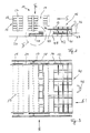
- a rack storage 11 for cassettes 12 containing rod-shaped material essentially consists of shelves 13 arranged next to one another transversely to the longitudinal extent of the cassettes 12 and separated from one another by rack aisles 14.
- the shelves have support arms 15 (see also FIG. 23) which extend horizontally and transversely to the longitudinal direction of the material in the adjacent shelf aisle to form shelf compartments for the cassettes 12, the cassettes engaging with end supports 16 in the form of a U-shaped profile can be brought with the support arms 15.
- the support arms 15 are attached to terminal supports 17 of the shelves 13, which are connected together at their upper end by rails 18 for a storage and retrieval unit 19.
- This storage and retrieval unit 19 is essentially an overhead crane with a lowerable load beam 20 on both sides of the shelves (see FIGS. 7 to 14), load beams 20 being guided over rollers 21 on the shelf supports 17 and also from DE OS 36 02 201 known manner bear fork-shaped load-carrying means 22 which can be brought into engagement with the supports 16 of the cassettes 12. It goes without saying that the load bars 20 arranged on both sides of the shelves 13, which can be raised and lowered via chains 23 starting from the crane 19, are synchronized with one another with regard to their movements.
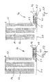
- the juxtaposed arrangement of shelves 13 can be passed underneath along a track 24 arranged between the shelf supports 17 transversely to the longitudinal extent of the cassettes 12 by a transport carriage 25, which is shown in FIGS. 1 and 2 overall in a transverse or end view, the details of which, however, are based on 4 to 6 can be explained.
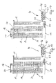
- the transport trolley has a frame-shaped chassis 30 on which there are three receiving places 1, 2, 3 for cassettes 12.
- the middle receiving space between two levels can be raised and lowered with the aid of, for example, cylinder-piston units 31, 32, the stroke range being greater than the height of a cassette.
- the receiving space is essentially formed from a receptacle 33 which can be moved vertically with respect to the base frame or chassis 30 via scissor levers 34 which, in a manner known per se, by the cylinders shown in FIG. Piston units 31, 32 can be actuated.
- the receptacle 33 carries rollers 35, via which the cassette 12 can be moved transversely to the longitudinal extent of the rod-shaped material contained in the cassette.
- the rollers 35 can be driven in rotation in both directions.
- the receiving places 2 and 3 have rollers 36, 37 which can be driven in both directions, so that when the scissor levers 34 are lowered, the cassettes 12 can be exchanged between the receiving places 1, 2 and 3.
- FIG. 6 also shows how the chassis 30 of the transport carriage can be moved on the rails 24 via wheels 38, 39.
- This station has two on top of each other on a frame 41 arranged receiving levels 42, 43 for the cassettes 12, in which case both receiving levels are equipped with roller conveyors 44, 45 which can be driven in both directions and correspond to the rollers or roller conveyors 35, 36 and 37 of the transport carriage 25.
- the upper receiving plane 43 is longer than the lower receiving plane 42 by a cassette width in the direction of the transport carriage 25, so that the transport carriage 25 can approach the lower receiving plane 42 with its receiving station 3 (see FIG. 6) , while at the same time the receiving space 1 in its raised position fits the receiving plane 43.
- the receiving planes 42, 43 have space for a plurality of cassettes arranged next to one another.
- the last cassette space facing an operator 46 is formed by an elevator 47, which is only shown schematically and can be used to bring cassettes from the upper receiving plane 43 to the lower receiving plane 42 or vice versa.
- FIGS. 7 to 20 these figures each showing a side view of a section of a shelf storage in the illustration according to FIG. 2.
- the transport carriage 25 brings a cassette B, which was previously removed from the lower receiving level 42 and is located in the receiving place 3 (see FIG. 6) of the transport carriage 25, into the rack storage 11 accordingly the indicated arrow direction.
- the cassette B is then moved from the (with reference to FIG. 6) receiving space 3 by actuating the rollers 35 to 37 to the receiving space 2.
- the storage and retrieval unit 19 picks up a new cassette A from one of the shelves via the load bars 20 and the load-carrying means 22 located thereon.
- the transport carriage 25 with its central receiving position 1 reaches the foot end of the rack aisle 14 belonging to the cassette A, whereupon the storage and retrieval device 19 according to FIG. 10 places the next succeeding cassette A on the central receiving station 1 of the transport carriage.
- the transport carriage 25 moves according to FIG. 11 by a cassette width so that the storage and retrieval device can accommodate the cassette B to be returned on its support means 16, as shown in FIG. 12.
- the cassette B to be returned can be returned to the place previously occupied by the cassette A by the storage and retrieval unit 19.
- the transport carriage can now drive with the cassette A to the station 40, as can be seen in FIG. 14, which it then reaches in the position shown in FIG. 15.
- the cassette A is raised to the level of the upper receiving plane 43 by actuating the scissors levers 34 according to FIGS. 4 and 5, in order to actuate the rollers 35 on the one hand and the roller conveyor 44 on the other hand, to be transferred from the trolley to the upper receiving level.
- a next cassette C which has already been processed at the station, is transferred from the lower receiving plane 42 by actuating the roller tracks 45 and the rollers 37 to the receiving location 3 of the transport carriage 35, as shown in FIG. 16.
- the receiving space 1 is lowered again according to FIG. 17, and according to FIG. 18 the transport trolley can move down to the rack warehouse for the next round.
- a cassette G used up according to FIG. 17 can be lowered in the manner shown in FIG. 18 by the elevator 47 to the lower receiving plane 42 , as can be seen from Fig. 18. Then, by operating the roller conveyor 45, the cassette G is taken down from the elevator to the lower receiving level in the manner shown in FIG. 19. Now the elevator 47 moves up again, so that the next cassettes of the upper receiving level can be moved up by operating the roller conveyor 44. As a result, according to FIG. 20, the next cassette I is available on the lower receiving level for returning to the rack storage, while on the upper receiving level there is space for the cassette to be next fed to station 40.
- cassette change between transport car 25 and station 40 takes place in a short time Work train instead of the trolley 25 would not have to be moved.
- this cassette change corresponds only to the short time required, as was also necessary according to FIGS. 7 to 12 within the rack warehouse.
- the device described so far is placed on rows of shelves which are only provided with a station for storing and retrieving the material contained in the cassettes at their front end lying transversely to the longitudinal direction of the material.
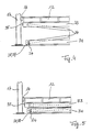
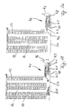
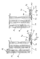
- FIG. 21 shows, in a manner corresponding to the detail view IV according to FIG. 1, a transport trolley which is generally provided with the number 50 and which can cooperate with a removal station 51 which is arranged in the longitudinal direction of the material next to the rack row 11.
- the transport carriage 50 is designed as follows, in the manner that can be seen in particular from FIGS. 21 and 22:
- the transport carriage 50 can be moved on the rails 24 already mentioned with the aid of wheels 52, of which at least one pair is synchronized by a shaft 53, via which the travel drive 55 also takes place with the aid of a motor 54.
- the drive on both sides of the transport carriage could equally well be carried out by a separate motor in a known manner, the motors being synchronized with one another with respect to the driving movements.
- the two other cassette positions 2 and 3 are basically given by a corresponding contact surface of the transport carriage 50 for the cassettes 12, which, as can best be seen from FIG. 21, are given by bars 59 transverse to the longitudinal direction of the cassettes.
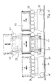
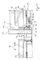
- the transport carriage 50 also has, in the region of both end faces of the cassettes 12, outer rails 60 carried by frame-fixed webs 61, by means of which carriages 62 of a transfer device for the cassettes can be moved on the transport carriage 50 transversely to the longitudinal extent of the cassettes 12.
- the carriages 62 of the transfer device can be adjusted in height via vertical, length-adjustable stands 63 with carriages 64 movable on the outer rails 60 and via a cylinder-piston unit 65, which on the one hand is on the top of the carriage 62 and on the other hand is pivotally articulated in the area of the respective undercarriage 64.
- the carriages 62 also have on both sides the support bracket 70 assigned to the two end faces of the respective cassette 12 for support and longitudinal and, if appropriate, transverse adjustment of the respective cassette, the horizontal leg 71 of which underpins the cassette while its vertical leg 72 is the system against the cassette end wall.
- the vertical leg 72 of the support bracket 70 can expediently be inclined or beveled in the region of its upper, free end from the cassette end wall.
- a cassette 12 can be moved back and forth between the positions 1, 2 and 3 by means of the transfer device (carriage 62) by the action of the cylinder-piston Aggregates 65 raised the respective cassette and is moved along the outer rails 60 by driving the trolleys 64.
- 21 and 22 also show the synchronous, reciprocating drive of the carriages 62 via a motor 73 fastened to the transport carriage 50, which drives a shaft 75 via a chain 74, via the end spur gears 76 of which at both ends of the transport carriage an endless one Chain 77 rotates, which is guided over deflection wheels 78, 79, 80 with its lower, horizontally continuous run through a coupling 81 to the carriage 62.
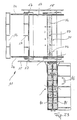
- an unloading station 51 is arranged on the outside of the rack storage. As shown in the top view according to FIG. 23, this has two places 90, 91 next to one another, which are designed as roller conveyors running in the longitudinal direction of the material. On one of these roller conveyors, the transport carriage 50 can deliver a cassette 12 from its central receiving space 1 by the rollers 57 of this receiving space being driven accordingly by the motor 57.
- the central receiving space 1 can be adjusted in height by scissor levers 95, which are articulated on the one hand on a frame 96 carrying the rollers 56 and on the other hand on the frame 59 of the transport carriage 50.
- the scissor levers can in turn be actuated in a manner known per se, for example by a cylinder-piston unit (not shown).
- the frame 96 has a shortened extent in the material longitudinal direction or in the longitudinal direction of the cassettes 12, so that the ends of the cassettes 12 having the supports 16 can protrude freely. One reason for this is so that the carriage 62 forming the transfer device can move freely past the frame 96.
- this also means that a station of the type already described can receive the cassettes with its roller conveyors.
- FIGS. 24 to 28 For this and for the mode of operation of the storage and retrieval station in connection with the transport carriage explained with reference to FIGS. 21 to 23, reference is made to FIGS. 24 to 28. Imagine that the dolly has brought a new cassette A towards the station for storage and retrieval in the manner already described with reference to FIGS. 7 to 15.
- frame 96 with cassette A located thereon is raised into the position shown in FIG. 25, after which it can then be moved into the position shown in FIG. 26.
- the formation of the roller conveyor 100 of the upper receiving plane 43 is made at least at the left first place so that the frame 96 can move in between the rollers 100, ie these rollers only support the respective cassette at their two longitudinal ends.
- at least the front position of the upper receiving plane 43 of the station 40 facing the transport carriage is open in the form of a fork in the direction of the shelves in such a way that the frame 96 can move in between the fork legs.
- the cassette A is placed on the upper receiving plane 43 by lowering the frame 96.
- the transfer device described with reference to FIGS. 21 and 22 can lift a cassette C to be returned from the lower receiving plane 42 of the station 40, here the roller conveyor 45 of the lower receiving plane, seen in the longitudinal direction of the material, must lie within the area occupied by the support bracket 72.
- the ends of the cassettes must protrude freely beyond the roller conveyor 45 in order to be able to be gripped by the transfer device or its support bracket 72.
Landscapes
- Engineering & Computer Science (AREA)
- Mechanical Engineering (AREA)
- Warehouses Or Storage Devices (AREA)
- Intermediate Stations On Conveyors (AREA)
Applications Claiming Priority (2)
| Application Number | Priority Date | Filing Date | Title |
|---|---|---|---|
| DE4016810A DE4016810C1 (fr) | 1990-05-25 | 1990-05-25 | |
| DE4016810 | 1990-05-25 |
Publications (2)
| Publication Number | Publication Date |
|---|---|
| EP0458021A1 true EP0458021A1 (fr) | 1991-11-27 |
| EP0458021B1 EP0458021B1 (fr) | 1993-09-08 |
Family
ID=6407149
Family Applications (1)
| Application Number | Title | Priority Date | Filing Date |
|---|---|---|---|
| EP91103573A Expired - Lifetime EP0458021B1 (fr) | 1990-05-25 | 1991-03-08 | Entrepôt avec rayonnages pour matériel recueilli dans des cassettes autoporteuses |
Country Status (4)
| Country | Link |
|---|---|
| US (1) | US5156514A (fr) |
| EP (1) | EP0458021B1 (fr) |
| JP (1) | JPH04226202A (fr) |
| DE (2) | DE4016810C1 (fr) |
Cited By (33)
| Publication number | Priority date | Publication date | Assignee | Title |
|---|---|---|---|---|
| EP2316755A1 (fr) * | 2009-10-28 | 2011-05-04 | Dr. Ing. h.c. F. Porsche AG | Station de commissionnement |
| AT509693A1 (de) * | 2010-04-02 | 2011-10-15 | Tgw Mechanics Gmbh | Verfahren zum kommissionieren, kommissionierstation und kommissioniersystem |
| AT14005U1 (de) * | 2010-04-02 | 2015-02-15 | Tgw Mechanics Gmbh | Verfahren zum kommissionieren, kommissionierstation und kommissioniersystem |
| CN110510318A (zh) * | 2019-09-05 | 2019-11-29 | 北京极智嘉科技有限公司 | 一种支架、搬运系统及搬运方法 |
| WO2019238697A1 (fr) * | 2018-06-12 | 2019-12-19 | Autostore Technology AS | Système de stockage automatisé |
| WO2019238694A1 (fr) * | 2018-06-12 | 2019-12-19 | Autostore Technology AS | Système de stockage |
| WO2019238645A1 (fr) * | 2018-06-12 | 2019-12-19 | Autostore Technology AS | Véhicule de livraison, système de stockage et de récupération automatisé et procédé de transport de contenants de stockage entre une grille de stockage et de récupération automatisée et un deuxième emplacement |
| WO2019238641A1 (fr) * | 2018-06-12 | 2019-12-19 | Autostore Technology AS | Système et procédés applicables de collecte d'articles à partir de conteneurs de stockage à l'aide d'un opérateur robotique |
| WO2019238639A1 (fr) * | 2018-06-12 | 2019-12-19 | Autostore Technology AS | Système de stockage et de transport de conteneurs de stockage |
| WO2019238664A1 (fr) * | 2018-06-12 | 2019-12-19 | Autostore Technology AS | Système de livraison doté d'un point d'accès et procédé d'accès à un point d'accès du système de livraison |
| CN110861925A (zh) * | 2019-10-10 | 2020-03-06 | 广州秉优信息科技有限公司 | 一种用于相同货物的码垛方法及系统 |
| WO2020115149A1 (fr) * | 2018-12-04 | 2020-06-11 | Kardex Produktion Deutschland Gmbh | Ensemble de stockage pourvu de systèmes de stockage disposés les uns à côté des autres et d'un système de préparation de commandes présentant des chariots de préparation de commande mobiles en va-et-vient |
| WO2020126725A1 (fr) * | 2018-12-20 | 2020-06-25 | Autostore Technology AS | Station d'accès à un conteneur pour un système de stockage et de récupération automatisé |
| CN112262088A (zh) * | 2018-06-12 | 2021-01-22 | 自动存储科技股份有限公司 | 输送车辆、自动储存和取回系统及在自动储存和取回网格与第二位置之间运输储存容器的方法 |
| EP3782929A1 (fr) * | 2019-08-23 | 2021-02-24 | Jungheinrich Aktiengesellschaft | Chariot de chargement en entrepôt de piles de récipient |
| CN112707073A (zh) * | 2019-10-25 | 2021-04-27 | 永恒力股份公司 | 堆垛存放组件和用于运行堆垛存放组件的方法 |
| CN112707074A (zh) * | 2019-10-25 | 2021-04-27 | 永恒力股份公司 | 堆垛存放组件 |
| CN112707075A (zh) * | 2019-10-25 | 2021-04-27 | 永恒力股份公司 | 堆垛存放组件 |
| US11352016B2 (en) | 2018-06-12 | 2022-06-07 | Autostore Technology AS | Storage system |
| US11479407B2 (en) | 2018-01-09 | 2022-10-25 | Autostore Technology AS | Displacement mechanism for a remotely operated vehicle |
| US11485375B2 (en) | 2018-06-12 | 2022-11-01 | Autostore Technology AS | Unloading arrangement and unloading station, as well as method of unloading an item from a storage container |
| US11498757B2 (en) | 2018-06-12 | 2022-11-15 | Autostore Technology AS | Storage system |
| US11505198B2 (en) | 2018-06-12 | 2022-11-22 | Autostore Technology AS | Vehicle tilting device, an access station, a delivery system and a method of accessing a storage container |
| US11572231B2 (en) | 2018-06-12 | 2023-02-07 | Autostore Technology AS | Storage system with modular container handling vehicles |
| US11603107B2 (en) | 2018-06-12 | 2023-03-14 | Autostore Technology AS | Unloading arrangement and unloading station, as well as method of unloading an item from a storage container |
| US11628849B2 (en) | 2018-06-12 | 2023-04-18 | Autostore Technology AS | Express bin lift for automated storage system |
| US11685391B2 (en) | 2018-06-12 | 2023-06-27 | Autostore Technology AS | Automated storage and retrieval system and a method of transporting storage containers between an automated storage and retrieval grid and a second location |
| US11691635B2 (en) | 2018-06-12 | 2023-07-04 | Autostore Technology AS | Storage grid with container accessing station with locking device to lock remotely operated vehicle |
| US11772685B2 (en) | 2018-06-12 | 2023-10-03 | Autostore Technology AS | System for storing and transporting storage containers |
| US11820389B2 (en) | 2018-06-12 | 2023-11-21 | Autostore Technology AS | Container accessing station with lifting device |
| US11873014B2 (en) | 2018-06-12 | 2024-01-16 | Autostore Technology AS | Delivery system with an access point and a method of accessing an access point of the delivery system |
| US11891095B2 (en) | 2018-06-12 | 2024-02-06 | Autostore Technology AS | Method for handling malfunctioning vehicles on a rail system and a storage and retrieval system using such a method |
| US11975744B2 (en) | 2018-06-12 | 2024-05-07 | Autostore Technology AS | Method and system for controlling the operation of container handling vehicles and drones serving an automated storage and retrieval system |
Families Citing this family (27)
| Publication number | Priority date | Publication date | Assignee | Title |
|---|---|---|---|---|
| DE4126669A1 (de) * | 1991-08-13 | 1993-02-18 | Stopa Stahlbau Gmbh & Co Kg | Vorrichtung zur bedienung eines regals zur lagerung von auf paletten befindlichem material |
| US5354169A (en) * | 1991-11-12 | 1994-10-11 | Advanced Technik Gmbh | Storage system for rods |
| US5582497A (en) * | 1992-01-29 | 1996-12-10 | Wing Labo Co., Ltd. | Automatic warehouse system |
| DE4213565A1 (de) * | 1992-04-24 | 1993-10-28 | Keuro Maschinenbau Gmbh | Vorrichtung zur Zusammenstellung von Materialkommissionen aus in einer Wabenregalanlage eingelagertem Lagergut |
| DE9214516U1 (fr) * | 1992-10-27 | 1992-12-17 | Keuro Maschinenbau Gmbh & Co Kg, 7590 Achern, De | |
| DE4317144C2 (de) * | 1993-05-24 | 1996-11-07 | Domag S A H | Regallager |
| JP3344850B2 (ja) * | 1993-12-28 | 2002-11-18 | 株式会社リコー | 部品供給装置 |
| US5672040A (en) * | 1994-03-07 | 1997-09-30 | Sony Corporation | Parts feeding apparatus and parts feeding process |
| DE4416103C2 (de) * | 1994-04-19 | 1999-01-07 | Bellheimer Metallwerk Gmbh | Hochregal |
| DE4439603C2 (de) * | 1994-11-05 | 1999-07-08 | Scheer & Cie C F | Plattenzuführvorrichtung |
| DE29517134U1 (de) * | 1995-10-28 | 1995-12-21 | Keuro Besitz Gmbh & Co | Vorrichtung zum Lagern und Transportieren von langen Werkstücken |
| US6558102B2 (en) * | 1997-08-29 | 2003-05-06 | psb GmbH Förderanlagen und Lagertechnik | High storage shelf system for hanging goods |
| DE29915108U1 (de) * | 1999-08-28 | 2000-03-16 | Kuttler Hans Juergen | Anlage zum Be- bzw. Weiterverarbeiten von Leiterplatten |
| DE10119229B4 (de) * | 2001-04-19 | 2004-04-15 | Rohwedder Microtech Gmbh & Co. Kg | Werkstückträger-Wechseleinrichtung und Wechselverfahren für Werkstückträger |
| DE102008012877A1 (de) | 2008-03-06 | 2009-09-24 | Psb Intralogistics Gmbh | Kommissioniereinrichtung und Verfahren zum Kommissionieren |
| DE102008031811A1 (de) * | 2008-06-26 | 2009-12-31 | Rofobox Gmbh | Serviettenfaltvorrichtung |
| DE102008035651A1 (de) * | 2008-07-31 | 2010-02-11 | Bellheimer Metallwerk Gmbh | Hängelagerung auf übereinander liegenden Lagerplätzen |
| US20110073534A1 (en) * | 2009-09-28 | 2011-03-31 | Niels Linge | Sorting Installation and Method for Sorting Articles |
| ATE543759T1 (de) * | 2009-11-27 | 2012-02-15 | Psb Intralogistics Gmbh | Kommissioniereinrichtung und verfahren zum kommissionieren |
| AT511867A1 (de) | 2011-09-05 | 2013-03-15 | Tgw Mechanics Gmbh | Kommissionierstation und verfahren zum kommissionieren von artikeln aus ladehilfsmitteln |
| DK2620389T3 (en) * | 2012-01-26 | 2016-03-07 | Siemens Ag | Attachment for the blades of a wind turbine and method of transporting blades of a wind turbine thus |
| DE102013005615A1 (de) * | 2013-04-04 | 2014-10-09 | Atlantic C Handels- Und Beratungs-Gmbh | Verfahren und Vorrichtung zum Beladen einer Palette |
| CN105540125B (zh) * | 2016-02-04 | 2019-04-23 | 杭州南江机器人股份有限公司 | 一种仓储自动流转系统 |
| IT201700091532A1 (it) * | 2017-08-08 | 2019-02-08 | Nuova Sima Spa | Sistema di trasporto ed immagazzinamento di piastrelle |
| DE102018215780A1 (de) * | 2018-09-18 | 2020-03-19 | Robert Bosch Gmbh | Vorrichtung und Verfahren zum Handhaben von Lagereinheiten |
| EP3960657B1 (fr) * | 2020-08-26 | 2024-03-27 | Jungheinrich Aktiengesellschaft | Agencement de couches d'empilage |
| NO20210679A1 (en) * | 2021-05-28 | 2022-11-29 | Autostore Tech As | An automated storage and retrieval system with a dynamic storage section and a method of using same |
Citations (4)
| Publication number | Priority date | Publication date | Assignee | Title |
|---|---|---|---|---|
| US4010855A (en) * | 1975-02-27 | 1977-03-08 | Litton Systems, Inc. | Warehouse system with pan transfer apparatus |
| DE3602201A1 (de) * | 1986-01-25 | 1987-10-08 | Keuro Maschinenbau Gmbh | Regalbediengeraet in form eines kranes |
| DE3708401A1 (de) * | 1987-03-14 | 1988-09-29 | Heinz Dipl Ing Dornieden | Langmateriallagereinrichtung und verfahren zu seinem betreiben |
| US4787804A (en) * | 1985-09-16 | 1988-11-29 | Aktiebolaget Knight Konsulterande Ingenjorer | Material handling system |
Family Cites Families (10)
| Publication number | Priority date | Publication date | Assignee | Title |
|---|---|---|---|---|
| DE255114C (fr) * | ||||
| US3426922A (en) * | 1967-04-07 | 1969-02-11 | Dormont Allen Co Inc | Order picking mechanism |
| US3978995A (en) * | 1973-02-15 | 1976-09-07 | Rapistan, Incorporated | Mobile tier picking apparatus for a warehousing system |
| DE2925469C2 (de) * | 1979-06-23 | 1982-07-08 | Stolzer-Lagertechnik GmbH, 7590 Achern | Einrichtung zur Lagerung von stangenförmigem Material und zur selbsttätigen, programmgesteuerten Versorgung einer Trennmaschine mit diesem Material |
| US4450400A (en) * | 1981-12-04 | 1984-05-22 | Gwyn Marion V | Battery replacement system for electric vehicles |
| IT1187368B (it) * | 1985-05-10 | 1987-12-23 | Gd Spa | Sistema di alimentazione automatizzata di materiale di produzione e/o confezionamento da un magazzino a linee di lavoro |
| JPS62105825A (ja) * | 1985-11-01 | 1987-05-16 | Matsushita Electric Ind Co Ltd | 物品搬送方法 |
| DE3733146C1 (en) * | 1987-10-01 | 1988-11-24 | Dalferth & Rogale Gmbh | Apparatus for shifting pallets for the purpose of making workpieces available at the workplace of factory workers |
| AT391845B (de) * | 1988-02-16 | 1990-12-10 | Tgw Transportgeraete Gmbh | Regalfoerderzeug |
| DE3922964A1 (de) * | 1989-07-12 | 1991-01-17 | Keuro Maschinenbau Gmbh | Verfahren und vorrichtung zur aus- und einlagerung von stangen- oder plattenfoermiges material enthaltenden kassetten bei einem regallager |
-
1990
- 1990-05-25 DE DE4016810A patent/DE4016810C1/de not_active Expired - Lifetime
-
1991
- 1991-03-08 DE DE91103573T patent/DE59100357D1/de not_active Expired - Fee Related
- 1991-03-08 EP EP91103573A patent/EP0458021B1/fr not_active Expired - Lifetime
- 1991-04-24 US US07/690,367 patent/US5156514A/en not_active Expired - Lifetime
- 1991-05-24 JP JP3119900A patent/JPH04226202A/ja active Pending
Patent Citations (4)
| Publication number | Priority date | Publication date | Assignee | Title |
|---|---|---|---|---|
| US4010855A (en) * | 1975-02-27 | 1977-03-08 | Litton Systems, Inc. | Warehouse system with pan transfer apparatus |
| US4787804A (en) * | 1985-09-16 | 1988-11-29 | Aktiebolaget Knight Konsulterande Ingenjorer | Material handling system |
| DE3602201A1 (de) * | 1986-01-25 | 1987-10-08 | Keuro Maschinenbau Gmbh | Regalbediengeraet in form eines kranes |
| DE3708401A1 (de) * | 1987-03-14 | 1988-09-29 | Heinz Dipl Ing Dornieden | Langmateriallagereinrichtung und verfahren zu seinem betreiben |
Cited By (53)
| Publication number | Priority date | Publication date | Assignee | Title |
|---|---|---|---|---|
| EP2316755A1 (fr) * | 2009-10-28 | 2011-05-04 | Dr. Ing. h.c. F. Porsche AG | Station de commissionnement |
| AT509693A1 (de) * | 2010-04-02 | 2011-10-15 | Tgw Mechanics Gmbh | Verfahren zum kommissionieren, kommissionierstation und kommissioniersystem |
| AT14005U1 (de) * | 2010-04-02 | 2015-02-15 | Tgw Mechanics Gmbh | Verfahren zum kommissionieren, kommissionierstation und kommissioniersystem |
| AT509693B1 (de) * | 2010-04-02 | 2019-04-15 | Tgw Mechanics Gmbh | Verfahren zum kommissionieren, kommissionierstation und kommissioniersystem |
| US11479407B2 (en) | 2018-01-09 | 2022-10-25 | Autostore Technology AS | Displacement mechanism for a remotely operated vehicle |
| US11548731B2 (en) | 2018-01-09 | 2023-01-10 | Autostore Technology AS | Displacement mechanism for a remotely operated vehicle |
| US11685391B2 (en) | 2018-06-12 | 2023-06-27 | Autostore Technology AS | Automated storage and retrieval system and a method of transporting storage containers between an automated storage and retrieval grid and a second location |
| US11691635B2 (en) | 2018-06-12 | 2023-07-04 | Autostore Technology AS | Storage grid with container accessing station with locking device to lock remotely operated vehicle |
| WO2019238641A1 (fr) * | 2018-06-12 | 2019-12-19 | Autostore Technology AS | Système et procédés applicables de collecte d'articles à partir de conteneurs de stockage à l'aide d'un opérateur robotique |
| WO2019238652A1 (fr) * | 2018-06-12 | 2019-12-19 | Autostore Technology AS | Système de stockage et de récupération automatisé et procédé de transport de contenants de stockage entre une grille de stockage et de récupération automatisée et un second emplacement |
| WO2019238639A1 (fr) * | 2018-06-12 | 2019-12-19 | Autostore Technology AS | Système de stockage et de transport de conteneurs de stockage |
| WO2019238664A1 (fr) * | 2018-06-12 | 2019-12-19 | Autostore Technology AS | Système de livraison doté d'un point d'accès et procédé d'accès à un point d'accès du système de livraison |
| US11975744B2 (en) | 2018-06-12 | 2024-05-07 | Autostore Technology AS | Method and system for controlling the operation of container handling vehicles and drones serving an automated storage and retrieval system |
| US11912314B2 (en) | 2018-06-12 | 2024-02-27 | Autostore Technology AS | Express bin lift for automated storage system |
| US11891095B2 (en) | 2018-06-12 | 2024-02-06 | Autostore Technology AS | Method for handling malfunctioning vehicles on a rail system and a storage and retrieval system using such a method |
| CN112262088A (zh) * | 2018-06-12 | 2021-01-22 | 自动存储科技股份有限公司 | 输送车辆、自动储存和取回系统及在自动储存和取回网格与第二位置之间运输储存容器的方法 |
| US11873014B2 (en) | 2018-06-12 | 2024-01-16 | Autostore Technology AS | Delivery system with an access point and a method of accessing an access point of the delivery system |
| US11834268B2 (en) | 2018-06-12 | 2023-12-05 | Autostore Technology AS | Storage system with modular container handling vehicles |
| US11820389B2 (en) | 2018-06-12 | 2023-11-21 | Autostore Technology AS | Container accessing station with lifting device |
| US11814058B2 (en) | 2018-06-12 | 2023-11-14 | Autostore Technology AS | Storage system |
| US11801874B2 (en) | 2018-06-12 | 2023-10-31 | Autostore Technology AS | Vehicle tilting device, an access station, a delivery system and a method of accessing a storage, etc |
| US11772685B2 (en) | 2018-06-12 | 2023-10-03 | Autostore Technology AS | System for storing and transporting storage containers |
| US11697422B2 (en) | 2018-06-12 | 2023-07-11 | Autostore Technology AS | Delivery vehicle, an automated storage and retrieval system and a method of transporting storage containers between an automated storage and retrieval grid and a second location |
| WO2019238645A1 (fr) * | 2018-06-12 | 2019-12-19 | Autostore Technology AS | Véhicule de livraison, système de stockage et de récupération automatisé et procédé de transport de contenants de stockage entre une grille de stockage et de récupération automatisée et un deuxième emplacement |
| US11628849B2 (en) | 2018-06-12 | 2023-04-18 | Autostore Technology AS | Express bin lift for automated storage system |
| US11352016B2 (en) | 2018-06-12 | 2022-06-07 | Autostore Technology AS | Storage system |
| CN112262088B (zh) * | 2018-06-12 | 2022-09-20 | 自动存储科技股份有限公司 | 输送车辆、自动储存和取回系统及在自动储存和取回网格与第二位置之间运输储存容器的方法 |
| CN115158949A (zh) * | 2018-06-12 | 2022-10-11 | 自动存储科技股份有限公司 | 储存系统、在储存系统中取回和储存物品的方法及转移方法 |
| WO2019238694A1 (fr) * | 2018-06-12 | 2019-12-19 | Autostore Technology AS | Système de stockage |
| US11485375B2 (en) | 2018-06-12 | 2022-11-01 | Autostore Technology AS | Unloading arrangement and unloading station, as well as method of unloading an item from a storage container |
| US11498757B2 (en) | 2018-06-12 | 2022-11-15 | Autostore Technology AS | Storage system |
| US11505198B2 (en) | 2018-06-12 | 2022-11-22 | Autostore Technology AS | Vehicle tilting device, an access station, a delivery system and a method of accessing a storage container |
| WO2019238697A1 (fr) * | 2018-06-12 | 2019-12-19 | Autostore Technology AS | Système de stockage automatisé |
| US11572231B2 (en) | 2018-06-12 | 2023-02-07 | Autostore Technology AS | Storage system with modular container handling vehicles |
| US11603107B2 (en) | 2018-06-12 | 2023-03-14 | Autostore Technology AS | Unloading arrangement and unloading station, as well as method of unloading an item from a storage container |
| WO2020115149A1 (fr) * | 2018-12-04 | 2020-06-11 | Kardex Produktion Deutschland Gmbh | Ensemble de stockage pourvu de systèmes de stockage disposés les uns à côté des autres et d'un système de préparation de commandes présentant des chariots de préparation de commande mobiles en va-et-vient |
| WO2020126725A1 (fr) * | 2018-12-20 | 2020-06-25 | Autostore Technology AS | Station d'accès à un conteneur pour un système de stockage et de récupération automatisé |
| EP3782929A1 (fr) * | 2019-08-23 | 2021-02-24 | Jungheinrich Aktiengesellschaft | Chariot de chargement en entrepôt de piles de récipient |
| US11261026B2 (en) | 2019-08-23 | 2022-03-01 | Jungheinrich Aktiengesellschaft | Container stacking storage system loading trolley having first and second lift drives |
| CN110510318A (zh) * | 2019-09-05 | 2019-11-29 | 北京极智嘉科技有限公司 | 一种支架、搬运系统及搬运方法 |
| CN110510318B (zh) * | 2019-09-05 | 2021-08-10 | 北京极智嘉科技股份有限公司 | 一种搬运系统及搬运方法 |
| CN110861925A (zh) * | 2019-10-10 | 2020-03-06 | 广州秉优信息科技有限公司 | 一种用于相同货物的码垛方法及系统 |
| EP3812305A1 (fr) * | 2019-10-25 | 2021-04-28 | Jungheinrich Aktiengesellschaft | Agencement de stockage par empilement et procédé de fonctionnement d'un agencement de stockage par empilement |
| CN112707074B (zh) * | 2019-10-25 | 2023-02-17 | 永恒力股份公司 | 堆垛存放组件 |
| EP3812307A1 (fr) * | 2019-10-25 | 2021-04-28 | Jungheinrich Aktiengesellschaft | Dispositif de stockage par empilement |
| CN112707075A (zh) * | 2019-10-25 | 2021-04-27 | 永恒力股份公司 | 堆垛存放组件 |
| CN112707074A (zh) * | 2019-10-25 | 2021-04-27 | 永恒力股份公司 | 堆垛存放组件 |
| US11834269B2 (en) | 2019-10-25 | 2023-12-05 | Jungheinrich Aktiengesellschaft | Stacking storage arrangement and method for operating a stacking storage arrangement |
| CN112707073A (zh) * | 2019-10-25 | 2021-04-27 | 永恒力股份公司 | 堆垛存放组件和用于运行堆垛存放组件的方法 |
| US11702285B2 (en) | 2019-10-25 | 2023-07-18 | Jungheinrich Aktiengesellschaft | Stacking storage arrangement |
| EP3812306A1 (fr) * | 2019-10-25 | 2021-04-28 | Jungheinrich Aktiengesellschaft | Dispositif de stockage par empilement |
| CN112707075B (zh) * | 2019-10-25 | 2023-02-17 | 永恒力股份公司 | 堆垛存放组件 |
| CN112707073B (zh) * | 2019-10-25 | 2023-02-17 | 永恒力股份公司 | 堆垛存放组件和用于运行堆垛存放组件的方法 |
Also Published As
| Publication number | Publication date |
|---|---|
| US5156514A (en) | 1992-10-20 |
| EP0458021B1 (fr) | 1993-09-08 |
| DE4016810C1 (fr) | 1991-11-21 |
| JPH04226202A (ja) | 1992-08-14 |
| DE59100357D1 (de) | 1993-10-14 |
Similar Documents
| Publication | Publication Date | Title |
|---|---|---|
| EP0458021B1 (fr) | Entrepôt avec rayonnages pour matériel recueilli dans des cassettes autoporteuses | |
| EP0407703B1 (fr) | Procédé et dispositif pour stocker et déstocker des caissons contenant des matériaux en forme de bâton ou de plaque dans un magasin à rayonnage | |
| EP2794432B1 (fr) | Système de stockage sur rayonnages et son procédé de fonctionnement | |
| EP0389516B1 (fr) | Systeme de stockage a convoyeur, notamment systeme de stationnement de vehicules | |
| EP0656980B1 (fr) | Dispositif pour un stationnement a encombrement reduit d'automobiles | |
| DE202016009161U1 (de) | Lagersystem | |
| EP1695925A1 (fr) | Magasin à rayonnage et procédé pour transférer d'articles dans un magasin à rayonnage | |
| AT511490A1 (de) | Regallagersystem | |
| DE19636470C2 (de) | Vorrichtung zum Handhaben von Glasscheiben | |
| DE3602201C2 (fr) | ||
| DE2409284A1 (de) | Automatische stapelvorrichtung zum lageweisen stapeln von staeben, insbesondere walzprofilen | |
| EP0589844B1 (fr) | Magasin à haute performance avec des moyens pour stocker et prélever des marchandises | |
| DE4422240A1 (de) | Verfahren und Einrichtung zur Handhabung von Transportuntersätzen | |
| DE102019106033A1 (de) | Regalbediengerät zum Verladen von stapelfähigen Waren und Logistiksystem mit einem solchen Regalbediengerät | |
| DE4031883A1 (de) | Aufnahme- und abgabesystem fuer paletten und behaelter | |
| EP0608689B1 (fr) | Dispositif de transport avec ou moins un engin pour l'extraction et le rangement d'une charge dans des cellules de rayonnage | |
| DE4400829A1 (de) | Regalbediengerät | |
| DE3902080A1 (de) | Parkhaus | |
| EP0213289A1 (fr) | Dispositif pour stocker et déstocker des marchandises d'un rayonnage en nid d'abeilles | |
| EP0116152A2 (fr) | Dispositif pour stocker et retirer des profilés | |
| DE3435679A1 (de) | Verfahren zur ein- und ausstapelung von transporteinheiten in eine vielzahl von ablagestellen und regal-anlage zur durchfuehrung des verfahrens | |
| DE2802345A1 (de) | Vorrichtung zum umschlagen von ladeeinheiten | |
| DE3631602A1 (de) | Regalanordnung | |
| DE3113976C2 (de) | Maschine zum schichtenweisen Be- oder Entpalettieren von Stückgut | |
| EP1180491B1 (fr) | Transstockeur |
Legal Events
| Date | Code | Title | Description |
|---|---|---|---|
| PUAI | Public reference made under article 153(3) epc to a published international application that has entered the european phase |
Free format text: ORIGINAL CODE: 0009012 |
|
| AK | Designated contracting states |
Kind code of ref document: A1 Designated state(s): DE FR GB IT |
|
| 17P | Request for examination filed |
Effective date: 19911231 |
|
| 17Q | First examination report despatched |
Effective date: 19930217 |
|
| ITF | It: translation for a ep patent filed |
Owner name: BARZANO' E ZANARDO ROMA S.P.A. |
|
| GRAA | (expected) grant |
Free format text: ORIGINAL CODE: 0009210 |
|
| AK | Designated contracting states |
Kind code of ref document: B1 Designated state(s): DE FR GB IT |
|
| GBT | Gb: translation of ep patent filed (gb section 77(6)(a)/1977) |
Effective date: 19930902 |
|
| REF | Corresponds to: |
Ref document number: 59100357 Country of ref document: DE Date of ref document: 19931014 |
|
| ET | Fr: translation filed | ||
| ITTA | It: last paid annual fee | ||
| PLBI | Opposition filed |
Free format text: ORIGINAL CODE: 0009260 |
|
| 26 | Opposition filed |
Opponent name: FRIEDRICH REMMERT GMBH Effective date: 19940604 |
|
| PLBN | Opposition rejected |
Free format text: ORIGINAL CODE: 0009273 |
|
| STAA | Information on the status of an ep patent application or granted ep patent |
Free format text: STATUS: OPPOSITION REJECTED |
|
| 27O | Opposition rejected |
Effective date: 19950930 |
|
| PGFP | Annual fee paid to national office [announced via postgrant information from national office to epo] |
Ref country code: GB Payment date: 20001211 Year of fee payment: 11 |
|
| REG | Reference to a national code |
Ref country code: GB Ref legal event code: IF02 |
|
| PG25 | Lapsed in a contracting state [announced via postgrant information from national office to epo] |
Ref country code: GB Free format text: LAPSE BECAUSE OF NON-PAYMENT OF DUE FEES Effective date: 20020308 |
|
| GBPC | Gb: european patent ceased through non-payment of renewal fee |
Effective date: 20020308 |
|
| PGFP | Annual fee paid to national office [announced via postgrant information from national office to epo] |
Ref country code: FR Payment date: 20060322 Year of fee payment: 16 |
|
| REG | Reference to a national code |
Ref country code: FR Ref legal event code: ST Effective date: 20071130 |
|
| PG25 | Lapsed in a contracting state [announced via postgrant information from national office to epo] |
Ref country code: FR Free format text: LAPSE BECAUSE OF NON-PAYMENT OF DUE FEES Effective date: 20070402 |
|
| PGFP | Annual fee paid to national office [announced via postgrant information from national office to epo] |
Ref country code: DE Payment date: 20090305 Year of fee payment: 19 Ref country code: IT Payment date: 20090325 Year of fee payment: 19 |
|
| PG25 | Lapsed in a contracting state [announced via postgrant information from national office to epo] |
Ref country code: DE Free format text: LAPSE BECAUSE OF NON-PAYMENT OF DUE FEES Effective date: 20101001 |
|
| PG25 | Lapsed in a contracting state [announced via postgrant information from national office to epo] |
Ref country code: IT Free format text: LAPSE BECAUSE OF NON-PAYMENT OF DUE FEES Effective date: 20100308 |