EP0457935B2 - Dispositif de commande pour câbles Bowden - Google Patents
Dispositif de commande pour câbles Bowden Download PDFInfo
- Publication number
- EP0457935B2 EP0457935B2 EP19900109601 EP90109601A EP0457935B2 EP 0457935 B2 EP0457935 B2 EP 0457935B2 EP 19900109601 EP19900109601 EP 19900109601 EP 90109601 A EP90109601 A EP 90109601A EP 0457935 B2 EP0457935 B2 EP 0457935B2
- Authority
- EP
- European Patent Office
- Prior art keywords
- guide cylinder
- actuating device
- rotary knob
- electric motor
- bowden cables
- Prior art date
- Legal status (The legal status is an assumption and is not a legal conclusion. Google has not performed a legal analysis and makes no representation as to the accuracy of the status listed.)
- Expired - Lifetime
Links
Images
Classifications
-
- B—PERFORMING OPERATIONS; TRANSPORTING
- B60—VEHICLES IN GENERAL
- B60H—ARRANGEMENTS OF HEATING, COOLING, VENTILATING OR OTHER AIR-TREATING DEVICES SPECIALLY ADAPTED FOR PASSENGER OR GOODS SPACES OF VEHICLES
- B60H1/00—Heating, cooling or ventilating devices
- B60H1/00642—Control systems or circuits; Control members or indication devices for heating, cooling or ventilating devices
- B60H1/00814—Control systems or circuits characterised by their output, for controlling particular components of the heating, cooling or ventilating installation
- B60H1/00821—Control systems or circuits characterised by their output, for controlling particular components of the heating, cooling or ventilating installation the components being ventilating, air admitting or air distributing devices
- B60H1/00835—Damper doors, e.g. position control
- B60H1/00842—Damper doors, e.g. position control the system comprising a plurality of damper doors; Air distribution between several outlets
-
- F—MECHANICAL ENGINEERING; LIGHTING; HEATING; WEAPONS; BLASTING
- F16—ENGINEERING ELEMENTS AND UNITS; GENERAL MEASURES FOR PRODUCING AND MAINTAINING EFFECTIVE FUNCTIONING OF MACHINES OR INSTALLATIONS; THERMAL INSULATION IN GENERAL
- F16C—SHAFTS; FLEXIBLE SHAFTS; ELEMENTS OR CRANKSHAFT MECHANISMS; ROTARY BODIES OTHER THAN GEARING ELEMENTS; BEARINGS
- F16C1/00—Flexible shafts; Mechanical means for transmitting movement in a flexible sheathing
- F16C1/10—Means for transmitting linear movement in a flexible sheathing, e.g. "Bowden-mechanisms"
- F16C1/12—Arrangements for transmitting movement to or from the flexible member
-
- G—PHYSICS
- G05—CONTROLLING; REGULATING
- G05G—CONTROL DEVICES OR SYSTEMS INSOFAR AS CHARACTERISED BY MECHANICAL FEATURES ONLY
- G05G7/00—Manually-actuated control mechanisms provided with one single controlling member co-operating with one single controlled member; Details thereof
- G05G7/02—Manually-actuated control mechanisms provided with one single controlling member co-operating with one single controlled member; Details thereof characterised by special provisions for conveying or converting motion, or for acting at a distance
Definitions
- the invention relates to an actuating device for Bowden cables.
- each Bowden cable is fixed in each case to a pulling and pushing element in the form of a slide piece which runs in a guide groove running parallel to the axis of rotation of the rotary knob is linearly guided in an operating housing receiving the rotary knob and which is in engagement with a screw thread on the surface of a guide cylinder via a sliding pin, which is rotatably mounted in the operating housing via bearing journals and can be actuated via the rotary knob.
- a further guide cylinder with a further sliding guide is provided for this purpose.
- the screw threads each extend over a partial circumferential area of each guide cylinder.
- GB-A-905 430 discloses an actuating device for Bowden cables with a guide cylinder which can be operated by a rotary knob parallel to its axis of rotation, the cylinder surface of which has a plurality of partially intersecting guide grooves which are self-contained over the circumference of the cylinder, by means of the driving cams can be moved back and forth by Bowden cable receptacles guided along axial rails in the direction of the cylinder axis when the guide cylinder is rotated.
- an actuating device for Bowden cables is known with a link plate that can be actuated by a rotary knob perpendicular to its axis of rotation and has a single circumferential, open-end link track, in which driving cams of two link levers, which are almost opposite each other, engage with one free end are rotatably mounted in a common housing-fixed pivot point between the driving cams and are connected at their other free ends to a Bowden cable.
- the actuation of a plurality of air flaps can be carried out in a substantially smaller installation space and in particular advantageously with a departure angle of the Bowden cables directed perpendicular to the axis of rotation of the rotary knob, in particular for the adjustment of a footwell air flap, a mid-level air flap and a defrost air flap for the pane level of a heating and / or air conditioning system of a motor vehicle can be achieved in that on a single guide cylinder a circumferential, self-contained guideway for a pivot lever for the footwell air flap, the mid-level air flap and the defrost, Air damper is provided.
- An easy-to-use actuation is achieved by a guide course with a transition from an open to a closed position or from a closed to an open position of each air flap when the rotary knob or the guide cylinder is actuated in the same direction.
- an indirect actuation of the guide cylinder by the rotary knob by means of an interposed electric motor is provided, expediently only an electrical setpoint from the rotary knob being preset to a potentiometer and then the electric motor driving the guide cylinder depending on the preset setpoint.
- the compactness of such a drive can be further increased in that the electric motor is arranged within the guide cylinder and expediently meshes directly or indirectly via a gear wheel on its shaft end with a circumferential internal ring gear on the inner circumferential surface of the guide cylinder.
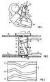
- FIG. 2 shows an insight into an operating device 1 which is open at the top and which is arranged on the dashboard of a motor vehicle.
- setting elements for example for the temperature and the air quantity of an air conditioning unit shown schematically in FIG.
- a motor vehicle for example, a footwell air flap F, a mid-level air flap M and a defrost air flap D are actuated for at least the front window plane.
- a differently high air volume flow can enter the corresponding channels, which is conveyed on the input side of the air conditioning unit by a fan V and via an evaporator K or a heat exchanger WT with different cold air or warm air proportions depending on the specification of the temperature setting element is.
- the footwell air flap F, the mid-level air flap M and the defrost air flap D are actuated via Bowden cables 2 or 3 or 4 depending on the position of the rotary knob D1 on the control unit B.
- the ends of the Bowden cables 2 and 3 and 4 are fastened in swivel levers 5 and 6 and 7, of which only the swivel lever 6 can be shown in full view and the swivel lever 7 in partial view in the illustration according to FIG.
- the pivot levers 5 or 6 or 7 can each be pivoted about a pivot axis 51 or 61 or 71, of which only the pivot axis 61 of the pivot lever 6 is shown in FIG. 2.
- the opposite ends of the pivot levers 5 or 6 or 7 facing away from the respective attachment points 52 or 62 or 72 of the Bowden cables 2 or 3 or 4 have guide pins 53 or 63 which run parallel to the respective pivot axes 51 or 61 or 71 or 73, which each engage in a self-contained guideway 11 or 12 or 13 which extends over the circumference of the guide cylinder 1 and is guided by the guideways in a rail-like manner when the guide cylinder 1 is actuated by the rotary knob D1 and pivoted about the pivot axes in this way that the Bowden cables 2 and 3 and 4 are actuated in the outgoing directions shown.
- FIG 3 shows the development of the outer circumference of the guide cylinder 1, from which the self-contained guideways 11 or 12 or 13 for the pivot levers 5 or 6 or 7 can be seen, which extend over the entire circumference;
- FIG 3 shows in particular that the left end of the development coincide with the right end of the development in the sense of a closed circumferential respective guideway.
- the mutual course of the guideways 11 or 12 or 13 to one another characterizes the respective mutual position of the air flaps F or M or D and thus the specific air distribution at each setting point of the rotary knob D1.
- the guide cylinder 1 according to the invention with its several guideways and the catches designed as pivot levers for the Bowden cables fulfills the function of a link plate which otherwise requires a larger installation space and, in a space-saving manner, a departure angle of the Bowden cables 2 or. 3 or 4, which runs approximately perpendicular to the axis of rotation 14 of the guide cylinder 1, with both a closing and an opening process or an opening due to the circumferential and self-contained guideway surrounding the entire circumference of the guide cylinder when the rotary knob D1 is actuated in the same direction of rotation - And a subsequent closing process is possible.
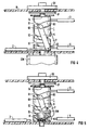
- the guide cylinder 1 is driven by a coupled electric motor EM, which is only receives its setpoint values from the rotary knob D1;
- the rotary knob D1 drives a potentiometer P, which is connected to the winding of the electric motor EM in a manner not shown here.
- the electric motor EM is coupled to the end of the guide cylinder 1 facing away from the rotary knob D1 to its cylinder axis 14; the electric motor EM itself is flanged to the control unit B on the outside.
- the electric motor EM is integrated into the interior of the guide cylinder 1 in an even more compact manner, and drives the guide cylinder 1 via a gear wheel 8 fastened to its shaft end in that the gear wheel 8 meshes with an internal toothing 9 extending over the inner circumference of the guide cylinder .
Landscapes
- Engineering & Computer Science (AREA)
- General Engineering & Computer Science (AREA)
- Mechanical Engineering (AREA)
- Physics & Mathematics (AREA)
- Health & Medical Sciences (AREA)
- Oral & Maxillofacial Surgery (AREA)
- Thermal Sciences (AREA)
- General Physics & Mathematics (AREA)
- Automation & Control Theory (AREA)
- Air-Conditioning For Vehicles (AREA)
- Fluid-Pressure Circuits (AREA)
- Mechanically-Actuated Valves (AREA)
Claims (9)
- Dispositif d'actionnement de plusieurs câbles Bowden (2 ou 3 ou 4), qui peuvent être actionnés indépendamment les uns des autres, en particulier pour le réglage de volets de chauffage et/ou de ventilation d'un véhicule automobile, au moyen de plus de deux pistes de guidage (11 ou 12 ou 13), séparées les unes des autres et ménagées à la surface latérale d'un cylindre en vue respectivement de l'entraînement guidé d'un câble Bowden, dans lequel il est prévu, sur un seul cylindre de guidage (1), plusieurs pistes de guidage (11 ou 12 ou 13), qui sont indépendantes les unes des autres et qui sont refermées sur elles-mêmes et sans croisement, pour respectivement un levier pivotant (6 ou 7 ou 8) prévu en tant qu'élément d'entraînement d'un câble Bowden, notamment pour un volet (F) de guidage de l'air en direction de l'espace situé au niveau des pieds, un volet (M) de guidage de l'air dans le plan médian ou un volet (D) de guidage de l'air de dégivrage, avec un guidage et/ou un tourillonnage en vue d'un départ des câbles Bowden (2 ou 3 ou 4) sensiblement perpendiculairement à l'axe (4) du cylindre de guidage, et il est prévu un tracé de la voie de guidage pour le passage de la position d'ouverture à la position de fermeture ou de la position de fermeture à la position d'ouverture des volets de circulation d'air (F ou M ou D) associés lors de l'actionnement du bouton rotatif (D1) ou du cylindre de guidage (1) dans le même sens de rotation.
- Dispositif d'actionnement suivant la revendicaton 1, caractérisé par un actionnement du cylindre de guidage (1) au moyen d'un bouton rotatif (D1) possédant un axe de rotation parallèle à l'axe (14) du cylindre de guidage.
- Dispositif d'actionnement suivant l'une des revendications 1 à 2, caractérisé par un actionnement indirect du cylindre de guidage (1) au moyen du bouton rotatif (D1) par l'intermédiaire d'un moteur électrique (EM) intercalé.
- Dispositif d'actionnement suivant la revendication 3, caractérisé par un transmetteur électrique de valeurs de consigne (potentiomètre P) réglable au moyen du bouton rotatif (D1), pour le moteur électrique (EM) raccordé électriquement.
- Dispositif d'actionnement suivant la revendication 4, caractérisé par le montage du potentiomètre (P) et/ou du moteur électrique (EM) sur un appareil de commande (B) qui loge le cylindre de guidage (1) et/ou le bouton rotatif (D1) et/ou les leviers pivotants (6 ou 7 ou 8).
- Dispositif d'actionnement suivant la revendication 5, caractérisé par le fait que le moteur électrique (EM) est couplé à l'axe (14) du cylindre de guidage (1), à l'extrémité de ce cylindre, située à l'opposé du bouton rotatif (D1).
- Dispositif d'actionnement suivant la revendication 3 et/ou 4, caractérisé par le fait que le moteur électrique (EM) est disposé à l'intérieur du cylindre de guidage (1).
- Dispositif d'actionnement suivant la revendication 6, caractérisé par le fait que le cylindre de guidage (1) comporte une couronne dentée intérieure périphérique (9), qui engrène indirectement ou directement avec une roue de transmission (8) montée sur une extrémité de l'arbre du moteur électrique (EM).
- Dispositif d'actionnement comportant un appareil de commande, qui est disposé sur le tableau de bord d'un véhicule automobile et loge au moins un bouton rotatif (D1), suivant au moins l'une des revendications 1 à 8, caractérisé par le fait que le dispositif d'actionnement pour des câbles Bowden (2 ou 3 ou 4) et/ou le moteur électrique (EM) et le potentiomètre (B) font partie intégrante de l'appareil de commande (B).
Priority Applications (3)
| Application Number | Priority Date | Filing Date | Title |
|---|---|---|---|
| EP19900109601 EP0457935B2 (fr) | 1990-05-21 | 1990-05-21 | Dispositif de commande pour câbles Bowden |
| ES90109601T ES2043176T5 (es) | 1990-05-21 | 1990-05-21 | Dispositivo de activacion para cables de traccion bowden. |
| DE90109601T DE59002574D1 (de) | 1990-05-21 | 1990-05-21 | Betätigungsvorrichtung für Bowdenzüge. |
Applications Claiming Priority (1)
| Application Number | Priority Date | Filing Date | Title |
|---|---|---|---|
| EP19900109601 EP0457935B2 (fr) | 1990-05-21 | 1990-05-21 | Dispositif de commande pour câbles Bowden |
Publications (3)
| Publication Number | Publication Date |
|---|---|
| EP0457935A1 EP0457935A1 (fr) | 1991-11-27 |
| EP0457935B1 EP0457935B1 (fr) | 1993-09-01 |
| EP0457935B2 true EP0457935B2 (fr) | 1996-04-17 |
Family
ID=8204009
Family Applications (1)
| Application Number | Title | Priority Date | Filing Date |
|---|---|---|---|
| EP19900109601 Expired - Lifetime EP0457935B2 (fr) | 1990-05-21 | 1990-05-21 | Dispositif de commande pour câbles Bowden |
Country Status (3)
| Country | Link |
|---|---|
| EP (1) | EP0457935B2 (fr) |
| DE (1) | DE59002574D1 (fr) |
| ES (1) | ES2043176T5 (fr) |
Families Citing this family (2)
| Publication number | Priority date | Publication date | Assignee | Title |
|---|---|---|---|---|
| DE19749214C1 (de) * | 1997-11-07 | 1998-10-22 | Preh Elektro Feinmechanik | Bedieneinheit zum Einstellen von Heizungs-, Klima- und/oder Lüftungsanlagen in Kraftfahrzeugen |
| JP2003054244A (ja) * | 2001-08-09 | 2003-02-26 | Denso Corp | 車両用空調装置 |
Family Cites Families (7)
| Publication number | Priority date | Publication date | Assignee | Title |
|---|---|---|---|---|
| GB905430A (en) * | 1960-07-15 | 1962-09-05 | Ford Motor Co | Improved heating and ventilating system |
| DE1630655B2 (de) * | 1967-11-14 | 1976-09-16 | Magirus Deutz Ag, 7900 Ulm | Einrichtung zum umschalten von heizklappen in fahrzeugen |
| JPS5719806A (en) * | 1980-07-09 | 1982-02-02 | Toyota Central Res & Dev Lab Inc | Fluctuation driving device |
| FR2502359B1 (fr) * | 1981-03-23 | 1985-07-05 | Renault | Systeme de commande manuelle d'un dispositif electrique |
| DE3136672C2 (de) * | 1981-09-16 | 1985-03-07 | Ford-Werke AG, 5000 Köln | Betätigungsvorrichtung für Bowdenzüge, insbesondere für Heizungs- und Lüftungsklappen in Kraftfahrzeugen |
| FR2558280B1 (fr) * | 1984-01-13 | 1986-11-21 | Peugeot | Dispositif de commande simultanee de deux pieces oscillantes telles que des volets d'un ensemble de climatisation de vehicule automobile |
| JPH01240314A (ja) * | 1988-03-22 | 1989-09-25 | Nissan Motor Co Ltd | 自動車用空調装置 |
-
1990
- 1990-05-21 EP EP19900109601 patent/EP0457935B2/fr not_active Expired - Lifetime
- 1990-05-21 ES ES90109601T patent/ES2043176T5/es not_active Expired - Lifetime
- 1990-05-21 DE DE90109601T patent/DE59002574D1/de not_active Expired - Lifetime
Also Published As
| Publication number | Publication date |
|---|---|
| EP0457935B1 (fr) | 1993-09-01 |
| ES2043176T3 (es) | 1993-12-16 |
| DE59002574D1 (de) | 1993-10-07 |
| ES2043176T5 (es) | 1996-06-01 |
| EP0457935A1 (fr) | 1991-11-27 |
Similar Documents
| Publication | Publication Date | Title |
|---|---|---|
| EP0465491B1 (fr) | Procede et dispositif pour reguler l'air frais dans le plan median d'un vehicule a moteur | |
| EP0738619B1 (fr) | Appareil de commande pour une installation de climatisation de véhicule avec un dispositif de chauffage et de réfrifération | |
| DE102011002606B4 (de) | Belüftungssteuervorrichtung für eine Heizungs- und/oder Klimaanlage eines Fahrzeugs | |
| EP0337382B1 (fr) | Système de ventilation d'un véhicule automobile | |
| EP0888916A2 (fr) | Système avec lamelles pour dispositifs d'aération pour régler la ventilation, notamment pour l'aération de véhicules à moteur | |
| DE102015112378B4 (de) | System zur Luftverteilung einer Klimaanlage eines Kraftfahrzeugs und Verfahren zum Betreiben des Systems | |
| EP0914979B1 (fr) | Unité de commande pour le réglage des installations de chauffage, de conditionnement d'air et/ou de ventilation des véhicules automobiles | |
| DE3001515A1 (de) | Vorrichtung zum steuern einer anlage zur klimatisierung des fahrgastraums eines automobils und verfahren zur durchfuehrung dieser steuerung | |
| EP1306241B1 (fr) | Dispositif de chauffage ou de climatisation d'un véhicule avec un volet de mixage et de distribution d'air | |
| DE60309377T2 (de) | Elektromotorisch betriebene Klappe für einen Lüftungskanal eines Kraftfahrzeugs | |
| EP0457935B2 (fr) | Dispositif de commande pour câbles Bowden | |
| DE19716229C2 (de) | Vorrichtung für eine Stellgliedersteuerung | |
| DE9005778U1 (de) | Betätigungsvorrichtung zur Verstellung von mehreren Heizungs- und/oder Lüftungsklappen in einem Kraftfahrzeug | |
| DE69310684T2 (de) | Vorrichtung für die Heizung, Lüftung und/oder Klimatisierung eines Fahrzeuginnenraumes | |
| DE4439992C1 (de) | Bedienvorrichtung für eine Heiz- oder Klimaanlage | |
| DE2403316C3 (de) | Steuervorrichtung für Klimaanlagen in Fahrzeugen, insbesondere Kraftfahrzeugen | |
| DE4420160A1 (de) | Übertragungsvorrichtung und Belüftungs-/Heizungs- und/oder Klimaanlage, insbesondere für Kraftfahrzeuge, die mit einer derartigen Übertragungsvorrichtung ausgestattet ist | |
| EP1048499A1 (fr) | Volet de ventilation | |
| EP0884204B1 (fr) | Dispositif de commande | |
| DE8903960U1 (de) | Einstellvorrichtung mit zumindest zwei in einem Gelenk drehbeweglich miteinander gekoppelten Hebeln | |
| DE4030173C2 (fr) | ||
| DE8710950U1 (de) | Vorrichtung zur Steuerung und Lenkung der aus einer Heizungs-, Belüftungs- und/oder Klimaanlage austretenden Luft | |
| DE19752260B4 (de) | Vorrichtung zur Betätigung einer Luftreglerklappe für eine Heizungs-, Belüftungs- und/oder Klimaanlage eines Kraftfahrzeugs | |
| DE4306015A1 (en) | Air-conditioning system motor vehicle interior - adjusts temp. and flow of air by computerised control of flaps for windscreen defrosting and passenger compartment heating | |
| DE2551861C3 (de) | Steuervorrichtung zum Klimatisieren von Räumen |
Legal Events
| Date | Code | Title | Description |
|---|---|---|---|
| PUAI | Public reference made under article 153(3) epc to a published international application that has entered the european phase |
Free format text: ORIGINAL CODE: 0009012 |
|
| 17P | Request for examination filed |
Effective date: 19901205 |
|
| AK | Designated contracting states |
Kind code of ref document: A1 Designated state(s): AT BE CH DE DK ES FR GB GR IT LI LU NL SE |
|
| RBV | Designated contracting states (corrected) |
Designated state(s): DE ES FR |
|
| 17Q | First examination report despatched |
Effective date: 19921229 |
|
| GRAA | (expected) grant |
Free format text: ORIGINAL CODE: 0009210 |
|
| AK | Designated contracting states |
Kind code of ref document: B1 Designated state(s): DE ES FR |
|
| REF | Corresponds to: |
Ref document number: 59002574 Country of ref document: DE Date of ref document: 19931007 |
|
| ET | Fr: translation filed | ||
| PLBI | Opposition filed |
Free format text: ORIGINAL CODE: 0009260 |
|
| 26 | Opposition filed |
Opponent name: PREH-WERKE GMBH & CO. KG Effective date: 19940513 |
|
| PLAW | Interlocutory decision in opposition |
Free format text: ORIGINAL CODE: EPIDOS IDOP |
|
| PUAH | Patent maintained in amended form |
Free format text: ORIGINAL CODE: 0009272 |
|
| STAA | Information on the status of an ep patent application or granted ep patent |
Free format text: STATUS: PATENT MAINTAINED AS AMENDED |
|
| 27A | Patent maintained in amended form |
Effective date: 19960417 |
|
| AK | Designated contracting states |
Kind code of ref document: B2 Designated state(s): DE ES FR |
|
| ET3 | Fr: translation filed ** decision concerning opposition | ||
| REG | Reference to a national code |
Ref country code: ES Ref legal event code: DC2A Kind code of ref document: T5 Effective date: 19960601 |
|
| REG | Reference to a national code |
Ref country code: ES Ref legal event code: PC2A Owner name: VALEO KLIMASYSTEME GMBH |
|
| REG | Reference to a national code |
Ref country code: ES Ref legal event code: PC2A Owner name: VALEO KLIMASYSTEME GMBH |
|
| PGFP | Annual fee paid to national office [announced via postgrant information from national office to epo] |
Ref country code: ES Payment date: 20090522 Year of fee payment: 20 |
|
| PGFP | Annual fee paid to national office [announced via postgrant information from national office to epo] |
Ref country code: FR Payment date: 20090529 Year of fee payment: 20 Ref country code: DE Payment date: 20090512 Year of fee payment: 20 |
|
| REG | Reference to a national code |
Ref country code: ES Ref legal event code: FD2A Effective date: 20100522 |
|
| PG25 | Lapsed in a contracting state [announced via postgrant information from national office to epo] |
Ref country code: ES Free format text: LAPSE BECAUSE OF EXPIRATION OF PROTECTION Effective date: 20100522 |
|
| PG25 | Lapsed in a contracting state [announced via postgrant information from national office to epo] |
Ref country code: DE Free format text: LAPSE BECAUSE OF EXPIRATION OF PROTECTION Effective date: 20100521 |