EP0457880B1 - Iff-bordantenne mit schaltbaren strahlungsdiagrammen - Google Patents
Iff-bordantenne mit schaltbaren strahlungsdiagrammen Download PDFInfo
- Publication number
- EP0457880B1 EP0457880B1 EP91900846A EP91900846A EP0457880B1 EP 0457880 B1 EP0457880 B1 EP 0457880B1 EP 91900846 A EP91900846 A EP 91900846A EP 91900846 A EP91900846 A EP 91900846A EP 0457880 B1 EP0457880 B1 EP 0457880B1
- Authority
- EP
- European Patent Office
- Prior art keywords
- iff
- diagram
- antenna
- parasitic
- diode
- Prior art date
- Legal status (The legal status is an assumption and is not a legal conclusion. Google has not performed a legal analysis and makes no representation as to the accuracy of the status listed.)
- Expired - Lifetime
Links
Images

Classifications
-
- H—ELECTRICITY
- H01—ELECTRIC ELEMENTS
- H01Q—ANTENNAS, i.e. RADIO AERIALS
- H01Q3/00—Arrangements for changing or varying the orientation or the shape of the directional pattern of the waves radiated from an antenna or antenna system
- H01Q3/44—Arrangements for changing or varying the orientation or the shape of the directional pattern of the waves radiated from an antenna or antenna system varying the electric or magnetic characteristics of reflecting, refracting, or diffracting devices associated with the radiating element
-
- G—PHYSICS
- G01—MEASURING; TESTING
- G01S—RADIO DIRECTION-FINDING; RADIO NAVIGATION; DETERMINING DISTANCE OR VELOCITY BY USE OF RADIO WAVES; LOCATING OR PRESENCE-DETECTING BY USE OF THE REFLECTION OR RERADIATION OF RADIO WAVES; ANALOGOUS ARRANGEMENTS USING OTHER WAVES
- G01S13/00—Systems using the reflection or reradiation of radio waves, e.g. radar systems; Analogous systems using reflection or reradiation of waves whose nature or wavelength is irrelevant or unspecified
- G01S13/74—Systems using reradiation of radio waves, e.g. secondary radar systems; Analogous systems
- G01S13/76—Systems using reradiation of radio waves, e.g. secondary radar systems; Analogous systems wherein pulse-type signals are transmitted
- G01S13/78—Systems using reradiation of radio waves, e.g. secondary radar systems; Analogous systems wherein pulse-type signals are transmitted discriminating between different kinds of targets, e.g. IFF-radar, i.e. identification of friend or foe
-
- H—ELECTRICITY
- H01—ELECTRIC ELEMENTS
- H01Q—ANTENNAS, i.e. RADIO AERIALS
- H01Q1/00—Details of, or arrangements associated with, antennas
- H01Q1/27—Adaptation for use in or on movable bodies
- H01Q1/28—Adaptation for use in or on aircraft, missiles, satellites, or balloons
-
- H—ELECTRICITY
- H01—ELECTRIC ELEMENTS
- H01Q—ANTENNAS, i.e. RADIO AERIALS
- H01Q3/00—Arrangements for changing or varying the orientation or the shape of the directional pattern of the waves radiated from an antenna or antenna system
- H01Q3/24—Arrangements for changing or varying the orientation or the shape of the directional pattern of the waves radiated from an antenna or antenna system varying the orientation by switching energy from one active radiating element to another, e.g. for beam switching
-
- H—ELECTRICITY
- H01—ELECTRIC ELEMENTS
- H01Q—ANTENNAS, i.e. RADIO AERIALS
- H01Q9/00—Electrically-short antennas having dimensions not more than twice the operating wavelength and consisting of conductive active radiating elements
- H01Q9/04—Resonant antennas
- H01Q9/30—Resonant antennas with feed to end of elongated active element, e.g. unipole
- H01Q9/40—Element having extended radiating surface
-
- H—ELECTRICITY
- H01—ELECTRIC ELEMENTS
- H01Q—ANTENNAS, i.e. RADIO AERIALS
- H01Q9/00—Electrically-short antennas having dimensions not more than twice the operating wavelength and consisting of conductive active radiating elements
- H01Q9/04—Resonant antennas
- H01Q9/30—Resonant antennas with feed to end of elongated active element, e.g. unipole
- H01Q9/42—Resonant antennas with feed to end of elongated active element, e.g. unipole with folded element, the folded parts being spaced apart a small fraction of the operating wavelength
Definitions
- the present invention relates to a fixed airborne IFF antenna.
- fixed airborne antenna is meant a non-orientable antenna fixed to the fuselage of the aircraft, generally under a flat radome, as opposed to scanning IFF antennas, a category to which the antenna of the invention does not belong. (which also seeks to remedy a certain number of drawbacks specific to these scanning antennas).
- EP-A-0.021.251 describes an exemplary embodiment of a fixed IFF antenna, integrated into a radar antenna.
- the IFF Identity Friend or Foe
- transponder standby
- interrogator challenge
- the front directional diagram is obtained by additional antennas, also two in number (back + belly), which are therefore added to the two omnidirectional standby antennas.
- a first object of the invention is to avoid this multiplication of antennas, by proposing a single universal antenna making it possible to selectively produce either an omnidirectional diagram (Eastern / Western), or a Western directional diagram, or an Eastern directional diagram.
- Another object of the present invention is to allow improved discrimination of the targets to be identified.
- the front directional diagram ⁇ presents a certain number of secondary lateral lobes, so that a close target situated in the direction D2 of one of these secondary lobes, therefore located outside the on-board radar field and therefore invisible to the pilot, may produce, if it is close, a more intense signal than a distant target which would be located in the direction D1 of the main lobe.
- the pilot will receive the response of the target located in the direction D2, target that he does not see, and not that of the target located in the direction D1, which will not be discriminated from other targets.
- control diagram or “diagram difference ( ⁇ ) "which is a rear directional diagram such as that illustrated in ⁇ in FIG. 1, and of a series of three successive coded pulses P1, P2 and P3 of the same amplitude.
- the IFF system will send the pulses P1 and P3 (called “interrogation” using the directional diagram before ⁇ (interrogation diagram or sum diagram), and the pulse P2 (called “control”) ) with the rear directional diagram ⁇ (control diagram or difference diagram).
- a second object of the invention is thus to allow, without increasing the number of antennas which will always be two (back + belly), the use of this technique on board an aircraft, without increasing the number of antennas and without having to resort to a scanning technique.
- the invention relates to an airborne IFF antenna as defined by claim 1.
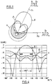
- FIG. 1 shows the three diagrams V, ⁇ and ⁇ necessary, respectively, for monitoring, identification and IFF discrimination.
- Figure 2 is an elevational view of the antenna of the invention, arranged inside a protective radome seen in section.
- Figure 3 is an enlarged view, in section, of the switching means located at the base of the parasitic elements of the antenna.
- FIG. 4 shows, in Cartesian coordinates, the three diagrams V, ⁇ and ⁇ recorded corresponding to the antenna of the invention.
- Figure 2 shows the antenna of the invention.
- This antenna is mounted on a metal plate 10 constituting, from the mechanical point of view, a sole plate used for mounting the antenna and the elements associated with it and forming, from the radio-electric point of view, a short-circuit plane. (ground plan).
- a box 11 encloses the various electronic switching circuits (the role of which will be explained below) and carries a coaxial connector 12 receiving the signal to be radiated (or delivering the picked up signal), and a connector 13 connected to the beam of cables sending the switching orders between the different diagrams.
- the sole 10 which will be screwed onto an opening made in the fuselage of the aircraft, supports a printed card 14 made of insulating material carrying a certain number of metallizations constituting the elements of the antenna.
- the assembly is enclosed in a radome 15, transparent from the radioelectric point of view, also fixed (screwed) to the fuselage of the aircraft.
- the realization of the antenna in plated form (that is to say in the form of metallization on printed board) is particularly suitable for an airborne application: gain in weight, volume and aerodynamics, in addition to the gain in price.
- the antenna of the invention essentially comprises a radiating element 20 forming a single primary source, with which are associated a number of parasitic radiating elements 30, 40, 50 selectively switchable between an inert state and a state connected to ground, according to orders sent to connector 13.
- the radiating element 20 is a broadband omnidirectional element, in order to be able to operate indifferently on both the Western and Eastern bands. It is produced in the form of a folded monopole comprising a main part 21, wide (typically of the order of ⁇ / 8 to ⁇ / 10, ⁇ being the average operating wavelength) so as to be broadband frequency; the part 21 is supplied at its base with 22 by the signal to be radiated and extended by a folded branch 23, connected at 24 to the ground plane 10 (this grounding also makes it possible to avoid the accumulation of static charges at the surface of the element).
- this active element 20 is associated a rear parasitic element or reflector 30 and a front parasitic element or director 40 (the direction of the front is indicated by the arrow 16).
- the primary radiating element 20 has a practically omnidirectional diagram making it possible to ensure the IFF standby, as can be seen on the statement V of figure 4 (all the readings of this figure are made at 1030 MHz).
- an additional switchable element 50 is provided to correct this radome effect in one of the bands (here, the Western band) and thus improve the omnidirectionality of the diagram in this band.
- the reflector 30, which will be switched to obtain the directional diagrams in the two bands, is a mixed element consisting in fact of two strands 31, 32 combined at their base and of different lengths (the shortest strand 31 corresponding to the Western band and the longest strand 32 at the Eastern band), which eliminates the need for two separate strands switched separately.
- Director 40 is made up of a single monopoly, just like Director 50.
- the elements 30, 40 and 50 are selectively switched by means of diodes 51 connecting them or not, depending on the control voltage + V applied, to the ground plane 10.
- the implementation of the invention required the resolution of several problems relating to the switching of the various parasitic elements.
- this generation also depends on the position of the diode on the parasitic element.
- the optimal position is also the place where the parasitic element has the lowest impedance; the advantage of switching to the base is therefore twofold.
- the diode is enclosed in a shield joined to ground, according to a configuration such as that illustrated in FIG. 3: the base 41 of the parasitic element 40 (this was only taken 'by way of example, the configuration being the same for the parasitic elements 30 and 50) is connected to the ground plane 10 by the PIN diode 51 enclosed in a tubular housing 17 forming a shield.
- the control voltage + V is applied to the base 41 of the parasitic element by means of a stop inductor 52, itself enclosed in the shield 17.
Landscapes
- Engineering & Computer Science (AREA)
- Remote Sensing (AREA)
- Radar, Positioning & Navigation (AREA)
- Physics & Mathematics (AREA)
- General Physics & Mathematics (AREA)
- Computer Networks & Wireless Communication (AREA)
- Astronomy & Astrophysics (AREA)
- Aviation & Aerospace Engineering (AREA)
- Variable-Direction Aerials And Aerial Arrays (AREA)
Claims (8)
- Auf einem Flugzeug montierte feste IFF-Antenne- mit einem strahlenden Primärelement (20),- und einer Mehrzahl von passiven Elementen (30, 40, 50), die dem strahlenden Primärelement zugeordnet sind und mindestens ein rückwärtiges Reflektorelement (30) und ein vorderes Direktorelement (40) enthalten, die hinter bzw. vor dem Primärelement liegen, dadurch gekennzeichnet, daß nur ein Primärelement vorgesehen ist, das aus einem breitbandigen umgebogenen Monopol besteht, und daß die Antenne weiter Schaltmittel (51, 52) enthält, die zwischen je eines der passiven Elemente und Masse eingefügt sind, und auf Wunsch jedes der Elemente selektiv in einen inerten Zustand und einen geerdeten Zustand umschalten können, wobei die elektrischen und geometrischen Kennwerte des strahlenden und der passiven Elemente und die Schaltsteuerungen so gewählt sind, daß das Eigendiagramm des strahlenden Primärelements so selektiv geändert wird, daß sich mindestens ergibt:- ein rundum wirkendes Diagramm (V) entsprechend dem IFF-Wachtmodus, für den der Reflektor und der Direktor sich im inerten Zustand befinden,- ein erstes Richtdiagramm entsprechend dem vorderen Richtdiagramm (Σ) im TFF-Abfragemodus gemäß einer ersten IFF-Norm in einem ersten Frequenzband,- ein zweites Richtdiagramm entsprechend dem vorderen Richtdiagramm im IFF-Abfragemodus gemäß einer zweiten IFF-Norm in einem zweiten Frequenzband, das sich vom ersten Frequenzband unterscheidet,- ein drittes Richtdiagramm entsprechend dem Kontrolldiagramm (Δ) im TFF-Abfragemodus gemäß der ersten IFF-Norm.
- Antenne nach Anspruch 1, dadurch gekennzeichnet, daß das Reflektorelement (30) zwei Stäbe (31, 32) besitzt, die der ersten bzw. zweiten IFF-Norm entsprechen.
- Antenne nach einem der vorhergehenden Ansprüche, dadurch gekennzeichnet, daß die Antenne unter einer Schutzhaube (15) montiert ist und die passiven Elemente außerdem ein passives Hilfselement (50) aufweisen, das dem strahlenden Primärelement zugeordnet und so eingeschaltet wird, daß das aufgrund der Haube veränderte Strahlungsdiagramm dieses strahlenden Primärelements in mindestens einem der Frequenzbänder korrigiert wird.
- Antenne nach den Ansprüchen 1 und 3, dadurch gekennzeichnet, daß die Schaltkonfiguration der passiven Elemente durch die nachfolgende Tabelle bestimmt ist:wobei 1 bedeutet "Diode leitet" und 0 bedeutet "Diode sperrt".

- Antenne nach einem der vorhergehenden Ansprüche, dadurch gekennzeichnet, daß die Schaltmittel für jedes der passiven Elemente- eine Diode (51), die zwischen einem Punkt (41) des passiven Elements und Massepotential liegt,- und Mittel (52, +V) aufweisen, um diese Diode selektiv vorzuspannen.
- Antenne nach Anspruch 5, dadurch gekennzeichnet, daß der Punkt (41) des passiven Elements, an den die Diode angeschlossen ist, ein Punkt minimaler Impedanz ist.
- Antenne nach Anspruch 6, dadurch gekennzeichnet, daß die Diode in einem der gemeinsamen Masseebene (10) möglichst nahen Punkt (41) des passiven Elements (40) angeschlossen ist und daß diese Diode in einem abgeschirmten Gehäuse (17) untergebracht ist, das sich zwischen dieser Masseebene und dem passiven Element befindet.
- Antenne nach einem der vorhergehenden Ansprüche, dadurch gekennzeichnet, daß das Primärelement und die passiven Elemente durch Metallbeschichtungen gebildet werden, die auf eine Druckkarte aufgebracht sind.
Applications Claiming Priority (3)
| Application Number | Priority Date | Filing Date | Title |
|---|---|---|---|
| FR8916264 | 1989-12-08 | ||
| FR8916264A FR2655778B1 (fr) | 1989-12-08 | 1989-12-08 | Antenne iff aeroportee a diagrammes multiples commutables. |
| PCT/FR1990/000892 WO1991009435A1 (fr) | 1989-12-08 | 1990-12-07 | Antenne iff aeroportee a diagrammes multiples commutables |
Publications (2)
| Publication Number | Publication Date |
|---|---|
| EP0457880A1 EP0457880A1 (de) | 1991-11-27 |
| EP0457880B1 true EP0457880B1 (de) | 1994-11-09 |
Family
ID=9388299
Family Applications (1)
| Application Number | Title | Priority Date | Filing Date |
|---|---|---|---|
| EP91900846A Expired - Lifetime EP0457880B1 (de) | 1989-12-08 | 1990-12-07 | Iff-bordantenne mit schaltbaren strahlungsdiagrammen |
Country Status (5)
| Country | Link |
|---|---|
| US (1) | US5231413A (de) |
| EP (1) | EP0457880B1 (de) |
| DE (1) | DE69014099T2 (de) |
| FR (1) | FR2655778B1 (de) |
| WO (1) | WO1991009435A1 (de) |
Families Citing this family (24)
| Publication number | Priority date | Publication date | Assignee | Title |
|---|---|---|---|---|
| CA2071714A1 (en) * | 1991-07-15 | 1993-01-16 | Gary George Sanford | Electronically reconfigurable antenna |
| FR2698726B1 (fr) * | 1992-11-30 | 1995-02-17 | Peugeot | Système d'antenne active à balayage électronique de faisceau. |
| DE4339162A1 (de) * | 1993-11-16 | 1995-05-18 | Lindenmeier Heinz | Funkantennenanordnung für den Dezimeterwellenbereich auf einem Kraftfahrzeug |
| US5717410A (en) * | 1994-05-20 | 1998-02-10 | Mitsubishi Denki Kabushiki Kaisha | Omnidirectional slot antenna |
| FR2743198B1 (fr) * | 1995-12-27 | 1998-02-27 | Eurocopter France | Procede pour compenser l'attenuation du rayonnement d'une antenne a haute frequence montee sur une structure ainsi perfectionnee |
| DE19813242A1 (de) * | 1998-03-26 | 1999-09-30 | Daimlerchrysler Aerospace Ag | Verfahren zur Zielerkennung Freund-Feind und Anordnung zur Durchführung des Verfahrens |
| JP2001036337A (ja) * | 1999-03-05 | 2001-02-09 | Matsushita Electric Ind Co Ltd | アンテナ装置 |
| US6570540B2 (en) * | 2001-09-14 | 2003-05-27 | The Boeing Company | Reflector assembly for minimizing reflections of electromagnetic energy from an antenna disposed within a radome |
| US6664938B2 (en) * | 2002-03-01 | 2003-12-16 | Ems Technologies Canada, Ltd. | Pentagonal helical antenna array |
| CN1653784A (zh) * | 2002-03-08 | 2005-08-10 | Ipr特许公司 | 自适应接收及全向发射天线矩阵 |
| US6876331B2 (en) * | 2002-03-14 | 2005-04-05 | Ipr Licensing, Inc. | Mobile communication handset with adaptive antenna array |
| DE102004051725A1 (de) * | 2004-10-23 | 2006-04-27 | Deutsche Telekom Ag | Antenne |
| US7696940B1 (en) | 2005-05-04 | 2010-04-13 | hField Technologies, Inc. | Wireless networking adapter and variable beam width antenna |
| US7385560B1 (en) * | 2006-09-26 | 2008-06-10 | Rockwell Collins, Inc. | Aircraft directional/omnidirectional antenna arrangement |
| FR2918804B1 (fr) * | 2007-07-12 | 2009-10-02 | Thales Sa | Pseudo-antenne omnidirectionnelle pour interrogateur ou systeme permettant les fonctions d'interrogation reponse et/ou d'ecoute passive |
| FR2936383B1 (fr) * | 2008-09-23 | 2010-11-12 | Thales Sa | Procede d'identification d'un equipement au sol ou en mer. |
| TWI422100B (zh) * | 2009-11-02 | 2014-01-01 | Ind Tech Res Inst | 可重構式多頻天線系統及其電子裝置 |
| IL214032A0 (en) * | 2010-07-12 | 2012-01-31 | Joseph Caspin | System and method for friend identification |
| CA2930159A1 (en) * | 2013-12-09 | 2015-06-18 | Dataflyte, Inc. | Airborne data collection |
| US20170194704A1 (en) * | 2016-01-05 | 2017-07-06 | John Mezzalingua Associates, LLC | Antenna having a beam interrupter for increased throughput |
| CA3020422A1 (en) * | 2016-04-20 | 2017-10-26 | Saab Ab | Method and system for operating an iff/ssr antenna |
| CN110034400A (zh) | 2018-01-05 | 2019-07-19 | 台达电子工业股份有限公司 | 天线装置和天线系统 |
| RU180876U1 (ru) * | 2018-04-18 | 2018-06-28 | Акционерное общество "Научно-исследовательский институт "Вектор" | Печатная антенна с интегрированным радиопрозрачным укрытием |
| US11569585B2 (en) | 2020-12-30 | 2023-01-31 | Industrial Technology Research Institute | Highly integrated pattern-variable multi-antenna array |
Family Cites Families (7)
| Publication number | Priority date | Publication date | Assignee | Title |
|---|---|---|---|---|
| US3283327A (en) * | 1963-08-26 | 1966-11-01 | Stoddart Aircraft Radio Inc | Sheet type fin antenna having loop fed excitation |
| US3404396A (en) * | 1967-01-24 | 1968-10-01 | Boeing Co | Airborne clear air turbulence radar |
| FR2196527B1 (de) * | 1972-08-16 | 1977-01-14 | Materiel Telephonique | |
| GB1471860A (en) * | 1974-07-02 | 1977-04-27 | Plessey Co Ltd | Radio antenna incorporating low-loss high relative permittivity dielectric material |
| DE2925104C2 (de) * | 1979-06-21 | 1984-06-20 | Siemens AG, 1000 Berlin und 8000 München | Segment-(Pillbox-) Radarantenne mit integrierter IFF-Antenne |
| CA1239223A (en) * | 1984-07-02 | 1988-07-12 | Robert Milne | Adaptive array antenna |
| JPH0644687B2 (ja) * | 1987-01-09 | 1994-06-08 | 日本電信電話株式会社 | 2周波共用プリントダイポ−ルアンテナ |
-
1989
- 1989-12-08 FR FR8916264A patent/FR2655778B1/fr not_active Expired - Fee Related
-
1990
- 1990-12-07 US US07/721,647 patent/US5231413A/en not_active Expired - Fee Related
- 1990-12-07 WO PCT/FR1990/000892 patent/WO1991009435A1/fr active IP Right Grant
- 1990-12-07 EP EP91900846A patent/EP0457880B1/de not_active Expired - Lifetime
- 1990-12-07 DE DE69014099T patent/DE69014099T2/de not_active Expired - Fee Related
Also Published As
| Publication number | Publication date |
|---|---|
| DE69014099T2 (de) | 1995-03-16 |
| WO1991009435A1 (fr) | 1991-06-27 |
| FR2655778A1 (fr) | 1991-06-14 |
| DE69014099D1 (de) | 1994-12-15 |
| FR2655778B1 (fr) | 1993-12-03 |
| US5231413A (en) | 1993-07-27 |
| EP0457880A1 (de) | 1991-11-27 |
Similar Documents
| Publication | Publication Date | Title |
|---|---|---|
| EP0457880B1 (de) | Iff-bordantenne mit schaltbaren strahlungsdiagrammen | |
| EP1407512B1 (de) | Antenne | |
| EP0012055B1 (de) | In Streifenleitertechnik ausgeführter Monopulsprimärstrahler und Antenne mit einem solchen Strahler | |
| WO2019034760A1 (fr) | Antenne plaquée présentant deux modes de rayonnement différents à deux fréquences de travail distinctes, dispositif utilisant une telle antenne | |
| EP1843170A1 (de) | Uwb-kurzimpulsradar | |
| EP0899814A1 (de) | Strahlende Struktur | |
| US20070194978A1 (en) | Uwb short-range radar | |
| FR2930079A1 (fr) | Capteur de rayonnement, notamment pour radar | |
| EP0013240B1 (de) | Gemeinsame Antenne für Primär- und Sekundärradar | |
| EP1568104A1 (de) | Mehrfachstrahlantenne mit photonischem bandlückenmaterial | |
| FR2496347A1 (fr) | Antenne de systeme de navigation omnidirectionnelle a tres haute frequence | |
| FR2806214A1 (fr) | Antenne reflectrice comportant une pluralite de panneaux | |
| WO2008028892A1 (fr) | Systeme multi-antenne a diversite de polarisation | |
| EP0435739B1 (de) | Magische Mikrowellenquelle und ihre Anwendung bei einer Antenne mit elektronischem Absuchen | |
| EP0493255A1 (de) | Schutzsystem für eine elektronische Einrichtung | |
| EP0585250B1 (de) | Rundstrahlende, gedruckte Zylinderantenne und Seeradar-Antwortgerät mit derartigen Antennen | |
| EP3900113B1 (de) | Elementare mikrostreifenantenne und gruppenantenne | |
| EP0991135B1 (de) | Selektive Antenne mit Frequenzumschaltung | |
| EP0033676A1 (de) | Gemeinsame Antenne für Primär-Radar und Sekundär-Radar | |
| EP0477102B1 (de) | Richtnetzwerk mit benachbarten Strahlerelementen für Funkübertragungssystem und Einheit mit einem derartigen Richtnetzwerk | |
| FR2930844A1 (fr) | Antenne rf d'emission et/ou de reception comportant des elements rayonnants excites par couplage electromagnetique sans contact | |
| EP0762534B1 (de) | Verfahren zur Verbreiterung des Strahlungsdiagramms einer Gruppenantenne mit verteilten Elementen in einem Volumen | |
| FR2943466A1 (fr) | Element rayonnant a bipolarisation | |
| EP0088681B1 (de) | Doppelreflektorantenne mit eingebautem Polarisationswandler | |
| EP0028185A1 (de) | Radarantenne mit Elementen, die ein pseudo-omnidirektionelles Diagramm abstrahlen |
Legal Events
| Date | Code | Title | Description |
|---|---|---|---|
| PUAI | Public reference made under article 153(3) epc to a published international application that has entered the european phase |
Free format text: ORIGINAL CODE: 0009012 |
|
| 17P | Request for examination filed |
Effective date: 19910704 |
|
| AK | Designated contracting states |
Kind code of ref document: A1 Designated state(s): DE GB |
|
| 17Q | First examination report despatched |
Effective date: 19930827 |
|
| RAP1 | Party data changed (applicant data changed or rights of an application transferred) |
Owner name: THOMSON-CSF |
|
| GRAA | (expected) grant |
Free format text: ORIGINAL CODE: 0009210 |
|
| AK | Designated contracting states |
Kind code of ref document: B1 Designated state(s): DE GB |
|
| REF | Corresponds to: |
Ref document number: 69014099 Country of ref document: DE Date of ref document: 19941215 |
|
| GBT | Gb: translation of ep patent filed (gb section 77(6)(a)/1977) |
Effective date: 19950116 |
|
| PLBE | No opposition filed within time limit |
Free format text: ORIGINAL CODE: 0009261 |
|
| STAA | Information on the status of an ep patent application or granted ep patent |
Free format text: STATUS: NO OPPOSITION FILED WITHIN TIME LIMIT |
|
| 26N | No opposition filed | ||
| PGFP | Annual fee paid to national office [announced via postgrant information from national office to epo] |
Ref country code: GB Payment date: 19961119 Year of fee payment: 7 |
|
| PGFP | Annual fee paid to national office [announced via postgrant information from national office to epo] |
Ref country code: DE Payment date: 19961120 Year of fee payment: 7 |
|
| PG25 | Lapsed in a contracting state [announced via postgrant information from national office to epo] |
Ref country code: GB Free format text: LAPSE BECAUSE OF NON-PAYMENT OF DUE FEES Effective date: 19971207 |
|
| GBPC | Gb: european patent ceased through non-payment of renewal fee |
Effective date: 19971207 |
|
| PG25 | Lapsed in a contracting state [announced via postgrant information from national office to epo] |
Ref country code: DE Free format text: LAPSE BECAUSE OF NON-PAYMENT OF DUE FEES Effective date: 19980901 |