EP0455837A1 - Ultraschall-Resonator - Google Patents
Ultraschall-Resonator Download PDFInfo
- Publication number
- EP0455837A1 EP0455837A1 EP90104490A EP90104490A EP0455837A1 EP 0455837 A1 EP0455837 A1 EP 0455837A1 EP 90104490 A EP90104490 A EP 90104490A EP 90104490 A EP90104490 A EP 90104490A EP 0455837 A1 EP0455837 A1 EP 0455837A1
- Authority
- EP
- European Patent Office
- Prior art keywords
- sound
- emitting part
- transducer
- transducers
- longitudinal
- Prior art date
- Legal status (The legal status is an assumption and is not a legal conclusion. Google has not performed a legal analysis and makes no representation as to the accuracy of the status listed.)
- Granted
Links
Images
Classifications
-
- B—PERFORMING OPERATIONS; TRANSPORTING
- B06—GENERATING OR TRANSMITTING MECHANICAL VIBRATIONS IN GENERAL
- B06B—METHODS OR APPARATUS FOR GENERATING OR TRANSMITTING MECHANICAL VIBRATIONS OF INFRASONIC, SONIC, OR ULTRASONIC FREQUENCY, e.g. FOR PERFORMING MECHANICAL WORK IN GENERAL
- B06B3/00—Methods or apparatus specially adapted for transmitting mechanical vibrations of infrasonic, sonic, or ultrasonic frequency
-
- G—PHYSICS
- G10—MUSICAL INSTRUMENTS; ACOUSTICS
- G10K—SOUND-PRODUCING DEVICES; METHODS OR DEVICES FOR PROTECTING AGAINST, OR FOR DAMPING, NOISE OR OTHER ACOUSTIC WAVES IN GENERAL; ACOUSTICS NOT OTHERWISE PROVIDED FOR
- G10K13/00—Cones, diaphragms, or the like, for emitting or receiving sound in general
Definitions
- the invention relates to a device for emitting ultrasonic energy into a liquid by means of a rod-shaped (tubular), sound-emitting part with the length lambda / 2 or a multiple thereof, which is coupled with an end face to a longitudinal transducer which carries out longitudinal vibrations.
- the sound transducer is attached to the wall of a liquid container so that the sound-emitting part is in the liquid.
- the longitudinal vibration transmitted to the sound radiating part by coupling to the sound transducer is partially converted into transverse vibrations so that the ultrasonic energy is radiated both in the longitudinal direction of the resonator and radially.
- only radial radiation is desired; the radiation emanating in the longitudinal direction, that is to say from the end face of the rod-shaped (tubular), sound-emitting part, cannot normally be utilized.
- the aim of the invention is therefore to provide a device which largely avoids this longitudinal loss radiation, that is to say causes the longitudinal vibration fed into the sound-radiating part by the sound transducer to be effectively converted into a radial transverse vibration.
- This is achieved in a manner according to the invention in that a further longitudinal transducer which executes synchronous longitudinal vibrations to the first transducer is coupled to the free end face of the sound-emitting part.
- the sound-radiating part has a free end that emits undesired longitudinal vibrations, but at this previously free end, according to the invention, a further similar and similar-vibrating sound transducer is attached or coupled, which not only emits in the longitudinal direction of the sound-radiating Partly prevented, but which also feeds ultrasonic energy into the sound-emitting part.
- a further similar and similar-vibrating sound transducer is attached or coupled, which not only emits in the longitudinal direction of the sound-radiating Partly prevented, but which also feeds ultrasonic energy into the sound-emitting part.
- Such a device can therefore radiate twice the ultrasonic energy radially into the liquid with the same geometric dimensions without any loss of power resulting from longitudinal vibrations.
- the sound-emitting part can be made of solid material or as a hollow body.
- the use of solid material has the advantage of a longer service life, since the cavitation pitting does not have as destructive effects here as with a hollow body.
- the hollow body on the other hand, has a somewhat more effective effect due to the larger vibration amplitude.
- the transducers can vibrate both in common and in push-pull.
- the decisive factor here is the length of the sound-emitting part of the device, which can be either an integer even or an odd integer of lambda / 2. This allows an optimal adaptation of the length of the device to the selected container size.
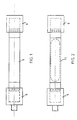
- Identical, synchronously vibrating sound transducers are arranged on the end faces of a sound-emitting part (1) made of solid material.
- the transducers are completely encapsulated so that the entire device can be immersed in liquid.
- the device can be attached on one side to the wall of a container. The encapsulation of the sound transducers prevents longitudinal vibrations from being released into the surrounding liquid by their counterweights.
- the two sound transducers (5, 6) vibrate synchronously and, for example, in synchronism. In this way, a longitudinal vibration is transmitted to the sound-emitting part (1), which is converted in a known manner into a transverse, radially radiating vibration.
- the length (1) of the sound-emitting part is lambda / 2 or an integer multiple thereof.
- Fig. 2 shows an essentially identical device, but with a tubular, sound-emitting part (11).
Abstract
Description
- Die Erfindung betrifft eine Vorrichtung zum Abstrahlen von Ultraschallenergie in eine Flüssigkeit mittels eines stabförmigen (rohrförmigen), schallabstrahlenden Teils mit der Länge lambda/2 oder eines Vielfachen hiervon, der mit einer Stirnseite an einen longitudinale Schwingungen ausführenden Schallwandler angekoppelt ist.
- Vorrichtungen der beschriebenen Art werden insbesondere in Ultraschall-Reinigungsanlagen eingesetzt. Hierbei wird der Schallwandler an der Wand eines Flüssigkeitsbehälters befestigt so, daß sich der schallabstrahlende Teil in der Flüssigkeit befindet. Die dem schallabstrahlenden Teil durch die Ankopplung an den Schallwandler übermittelte longitudinale Schwingung wird teilweise in transversale Schwingungen umgesetzt, so daß die Ultraschallenergie sowohl in Längsrichtung des Resonators wie auch radial abgestrahlt wird. Erwünscht ist allerdings im allgemeinen nur die radiale Abstrahlung; die in Längsrichtung, also von der Stirnfläche des stabförmigen (rohrförmigen), schallabstrahlenden Teils ausgehende Abstrahlung, kann normalerweise nicht verwertet werden. Um weitgehend die longitudinal eingespeiste Schwingung in eine radial vom schallabstrahlenden Teil ausgehende Schwingung umzuwandeln, wurde bereits schon vorgeschlagen (EP-B-44 800), den schallabstrahlenden Teil (Resonator) am Ort eines longitudinalen Schwingungsmaximums an eine Stirnfläche des Schallwandlers anzuschließen und die Gesamtlänge des Resonators auf ein ganzzahliges Vielfaches einer halben Wellenlänge (lambda/2) der vom Schallwandler in den Resonator eingespeisten Longitudinalschwingung abzustimmen. Durch das Ankoppeln des Resonators am Ort des Schwingungsmaximums des Schallwandlers wird dessen Gesamtleistung in den Reonator übertragen, der dadurch, daß seine Länge auf die Frequenz des Schallwandlers abgestimmt ist, maximale Abstrahlungsergebnisse aufweisen kann. Trotzdem stellt sich selbstverständlich auch bei dieser bekannten Vorrichtung eine unerwünschte longitudinale Verlustabstrahlung ein.
- Ziel der Erfindung ist es daher, eine Vorrichtung anzugeben, die möglichst weitgehend diese longitudinale Verlustabstrahlung vermeidet, also bewirkt, daß die von dem Schallwandler in den schallabstrahlenden Teil eingespeiste Longitudinalschwingung effektiv in eine radiale transversale Schwingung umgewandelt wird. Erreicht wird dies in erfindungsgemäßer Weise dadurch, daß an der freien Stirnseite des schallabstrahlenden Teils ein weiterer zu dem ersten Schallwandler synchrone longitudinale Schwingungen ausführender Schallwandler angekoppelt ist.
- Nicht mehr also wie bisher weist der schallabstrahlende Teil ein freies stirnseitiges Ende auf, das unerwünschte longitudinale Schwingungen abstrahlt, sondern an diesem bisher freien Ende ist nach der Erfindung ein weiterer gleichartiger und gleichschwingender Schallwandler angebracht beziehungsweise angekoppelt, der nicht nur das Abstrahlen in Längsrichtung des schallabstrahlenden Teils verhindert, sondern der zusätzlich auch noch Ultraschallenergie in den schallabstrahlenden Teil einspeist. Eine derartige Vorrichtung kann also bei gleichen geometrischen Abmessungen die doppelte Ultraschallenergie radial in die Flüssigkeit abstrahlen, ohne daß durch longitudinale Schwingungen eine Verlustleistung entsteht. Diese Abstrahlung kann dadurch maximiert werden, daß die Vorrichtung beidseits einer mittigen Querschnittsfläche des schallabstrahlenden Teils übereinstimmend ausgeführt ist, daß also die jeweils eingespeiste und damit auch die jeweils abgestrahlte Ultraschall-Energie gleich und gleich einem jeweiligen Maximum ist. Hierbei kann der schallabstrahlende Teil aus Vollmaterial oder als Hohlkörper ausgeführt sein. Die Verwendung von Vollmaterial hat den Vorteil einer höheren Lebensdauer, da sich hier der Kavitationslochfraß nicht so zerstörend auswirkt wie bei einem Hohlkörper. Der Hohlkörper hingegen wirkt sich durch größere Schwingungsamplitude etwas effektiver aus.
- Die Schallwandler können sowohl im Gleichtakt wie auch im Gegentakt schwingen. Maßgebend hierfür ist die Länge des schallabstrahlenden Teils der Vorrichtung, die entweder ganzzahlig gerade oder ganzzahlig ungerade von lambda/2 sein kann. Damit ist eine optimale Anpassung der Länge der Vorrichtung an die jeweils gewählte Behältergröße möglich.
- Schließlich wird auch noch vorgeschlagen, um eine separate Stromzuleitung zu dem weiteren Schallwandler zu vermeiden, daß dessen Stromzuführung durch den schallabstrahlenden Teil hindurch erfolgt.
- Auf der Zeichnung sind Ausführungsbeispiele der erfindungsgemaßen Vorrichtung schematisch dargestellt, und zwar zeigen
- Fig. 1
- eine Vorrichtung mit einem aus Vollmaterial bestehenden schallabstrahlenden Teil,
- Fig. 2
- die Vorrichtung mit einem rohrförmigen, schallabstrahlenden Teil.
- An den Stirnseiten eines aus Vollmaterial bestehenden schallabstrahlenden Teils (1) sind jeweils gleichartige, synchron schwingende Schallwandler angeordnet. Die Schallwandler sind vollkommen gekapselt, so daß die gesamte Vorrichtung in Flüssigkeit eingetaucht werden kann. Einseitig kann die Vorrichtung an der Wandung eines Behälters befestigt werden. Durch die Kapselung der Schallwandler wird vermieden, daß von deren Gegengewichten longitudinale Schwingungen in die umgebende Flüssigkeit abgegeben werden.
- Beim Betrieb dieser Vorrichtung schwingen die beiden Schallwandler (5, 6) synchron und beispielsweise im Gleichtakt. Hierdurch wird dem schallabstrahlenden Teil (1) eine longitudinale Schwingung übermittelt, die in bekannter Art und Weise in eine transversale radial abstrahlende Schwingung umgesetzt wird. Die Länge (1) des schallabstrahlenden Teils beträgt hierbei lambda/2 beziehungsweise ein ganzzahliges Vielfaches hiervon.
- Fig. 2 zeigt eine im wesentlichen gleich aufgebaute Vorrichtung, jedoch mit einem rohrförmigen, schallabstrahlenden Teil (11).
Claims (10)
- Vorrichtung zum Abstrahlen von Ultraschallenergie in eine Flüssigkeit mittels eines stabförmigen (rohrförmigen), schallabstrahlenden Teils mit der Länge lambda/2 oder eines Vielfachen hiervon, das mit einer Stirnseite an einen longitudinale Schwingungen ausführenden Schallwandler angekoppelt ist,
dadurch gekennzeichnet,
daß an der freien Stirnseite dem schallabstrahlenden Teils (1) ein weiterer zu dem ersten Schallwandler (5) synchrone longitudinale Schwingungen (f1 = f2) ausführender Schallwandler (6) angekoppelt ist. - Vorrichtung nach Anspruch 1,
dadurch gekennzeichnet,
daß die Vorrichtung beidseits einer mittigen Querschnittsfläche des schallabstrahlenden Teils (1) jeweils übereinstimmend ausgeführt ist. - Vorrichtung nach Anspruch 1 oder 2,
dadurch gekennzeichnet,
daß der schallabstrahlende Teil (1) ein Hohlkörper ist. - Vorrichtung nach Anspruch 1 oder 2,
dadurch gekennzeichnet,
daß der schallabstrahlende Teil (1) aus Vollmaterial ist. - Vorrichtung nach einem oder mehreren der Ansprüche,
dadurch gekennzeichnet,
daß die Ankopplung des schallabstrahlenden Teils (1) an die Schallwandler (5, 6) jeweils über Transformationsstücke (3, 4) erfolgt. - Vorrichtung nach Anspruch 5,
dadurch gekennzeichnet,
daß der Durchmesser des schallabstrahlenden Teils (1) grösser als derjenige der Ankopplungsfläche der Schallwandler (5, 6) ist. - Vorrichtung nach Anspruch 5,
dadurch gekennzeichnet,
daß der Durchmesser des schallabstrahlenden Teils (1) kleiner als derjenige der Ankopplungsfläche der Schallwandler (5, 6) ist. - Vorrichtung nach Anspruch 1,
dadurch gekennzeichnet,
daß die Schallwandler (5, 6) im Gleichtakt schwingen. - Vorrichtung nach Anspruch 1,
dadurch gekennzeichnet,
daß die Schallwandler (5, 6) im Gegentakt schwingen. - Vorrichtung nach einem oder mehreren der Ansprüche,
dadurch gekennzeichnet,
daß die Stromzuführung zu dem weiteren Schallwandler (6) durch den schallabstrahlenden Teil (1) hindurch erfolgt.
Priority Applications (8)
| Application Number | Priority Date | Filing Date | Title |
|---|---|---|---|
| ES199090104490T ES2031398T3 (es) | 1990-03-09 | 1990-03-09 | Resonador ultrasonico. |
| DE9090104490T DE59000126D1 (de) | 1990-03-09 | 1990-03-09 | Ultraschall-resonator. |
| EP90104490A EP0455837B1 (de) | 1990-03-09 | 1990-03-09 | Ultraschall-Resonator |
| AT90104490T ATE75974T1 (de) | 1990-03-09 | 1990-03-09 | Ultraschall-resonator. |
| DK90104490.9T DK0455837T3 (da) | 1990-03-09 | 1990-03-09 | Anordning til udstråling af ultralydenergi |
| JP3040025A JP3025323B2 (ja) | 1990-03-09 | 1991-03-06 | 液中へ超音波エネルギを放射するための装置 |
| US06/665,995 US5200666A (en) | 1990-03-09 | 1991-03-07 | Ultrasonic transducer |
| FI911174A FI99091C (fi) | 1990-03-09 | 1991-03-08 | Ultraääniresonaattori |
Applications Claiming Priority (1)
| Application Number | Priority Date | Filing Date | Title |
|---|---|---|---|
| EP90104490A EP0455837B1 (de) | 1990-03-09 | 1990-03-09 | Ultraschall-Resonator |
Publications (2)
| Publication Number | Publication Date |
|---|---|
| EP0455837A1 true EP0455837A1 (de) | 1991-11-13 |
| EP0455837B1 EP0455837B1 (de) | 1992-05-13 |
Family
ID=8203734
Family Applications (1)
| Application Number | Title | Priority Date | Filing Date |
|---|---|---|---|
| EP90104490A Expired - Lifetime EP0455837B1 (de) | 1990-03-09 | 1990-03-09 | Ultraschall-Resonator |
Country Status (8)
| Country | Link |
|---|---|
| US (1) | US5200666A (de) |
| EP (1) | EP0455837B1 (de) |
| JP (1) | JP3025323B2 (de) |
| AT (1) | ATE75974T1 (de) |
| DE (1) | DE59000126D1 (de) |
| DK (1) | DK0455837T3 (de) |
| ES (1) | ES2031398T3 (de) |
| FI (1) | FI99091C (de) |
Cited By (9)
| Publication number | Priority date | Publication date | Assignee | Title |
|---|---|---|---|---|
| DE4436054A1 (de) * | 1994-10-10 | 1996-04-11 | Wimmer Ulrich Dipl Ing Fh | Verfahren und Einrichtung zur Vermeidung von Kavitationsschäden |
| EP1065009A1 (de) * | 1999-07-02 | 2001-01-03 | TELSONIC AG für elektronische Entwicklung und Fabrikation | Vorrichtung und Verfahren zur Erzeugung und Abstrahlung von Ultraschallenergie |
| DE19724189C2 (de) * | 1997-06-02 | 2001-07-05 | Bandelin Electronic Gmbh & Co | Rohrförmige elektroakustische Vorrichtung zur Erzeugung von Ultraschallenergie |
| DE10034064C1 (de) * | 2000-07-13 | 2001-09-13 | Walter Martin Ultraschalltech | Vorrichtung zur Reinigung von porösem Material mittels Ultraschall |
| DE10013350A1 (de) * | 2000-03-17 | 2001-09-27 | Walter Martin Ultraschalltech | Vorrichtung zum Abstrahlen von Ultraschallenergie |
| EP2223742A1 (de) | 2009-02-06 | 2010-09-01 | BANDELIN electronic GmbH & Co. KG | Fluidreaktor |
| DE202015103011U1 (de) | 2014-06-06 | 2015-07-27 | Weber Ultrasonics Gmbh | Ultraschall-Konverter |
| DE202017100958U1 (de) | 2017-02-21 | 2017-03-06 | Weber Ultrasonics AG | Ultraschallschneidelement |
| CN107206426A (zh) * | 2014-12-15 | 2017-09-26 | 锡德雷特技术公司 | 模块化的可浸没超声波管状换能器 |
Families Citing this family (26)
| Publication number | Priority date | Publication date | Assignee | Title |
|---|---|---|---|---|
| US5321333A (en) * | 1993-04-06 | 1994-06-14 | The United States Of America As Represented By The Secretary Of The Navy | Torsional shear wave transducer |
| GB9313901D0 (en) * | 1993-07-06 | 1993-08-18 | Chandler Brian | Linings for pipelines and passageways |
| DE19717397A1 (de) * | 1997-04-24 | 1998-11-05 | Vladimir Dr Abramov | Gerät zur Einkopplung von Ultraschall in ein flüssiges oder pastöses Medium |
| DE19836194C1 (de) * | 1998-08-10 | 1999-12-30 | Basf Ag | Ultraschallwandler mit Schutzkappen |
| KR100299928B1 (ko) * | 1998-11-23 | 2001-10-29 | 황해웅 | 파우어초음파트랜스듀서 |
| DE60029212T2 (de) | 1999-04-08 | 2007-06-14 | Electric Power Research Institute, Inc., Palo Alto | Vorrichtung und verfahren zur ultraschallreinigung von bestrahlten kernbrennstabbündeln |
| EP1681107A3 (de) * | 1999-04-08 | 2013-07-31 | Electric Power Research Institute, Inc | Vorrichtung und Verfahren zur Ultraschallreinigung von bestrahlten Kernbrennstabbündeln |
| US6111337A (en) * | 1999-07-20 | 2000-08-29 | Christensen; Juan Carlos | Ultrasonic transducer dipole |
| KR100329284B1 (ko) * | 1999-08-05 | 2002-03-18 | 황해웅 | 날개형 초음파 트랜스듀서 |
| KR20010092834A (ko) * | 2000-03-27 | 2001-10-27 | 최동환 | 압전세라믹 음파 트랜스듀서 |
| AR028556A1 (es) * | 2001-05-08 | 2003-05-14 | Christensen Juan Carlos | Transductor tubular portrtil de ultrasonido |
| US6745590B1 (en) | 2003-01-13 | 2004-06-08 | American Power Conversion | Condensate removal system |
| JP2007523738A (ja) * | 2003-11-05 | 2007-08-23 | ザ・クレスト・グループ・インク | 複数の応答周波数を持つトランスデューサを用いた超音波処理方法および超音波処理装置 |
| DE102005007056A1 (de) * | 2005-02-15 | 2006-08-24 | Dieter Weber | Ultraschall-Stabschwinger |
| TWI393595B (zh) * | 2006-03-17 | 2013-04-21 | Michale Goodson J | 具有頻率掃描的厚度模式轉換器之超高頻音波處理設備 |
| ES2324249B1 (es) * | 2006-07-06 | 2010-05-13 | Universidad De Alcala | Afeitadora electrica con emisioon de ultrasonidos. |
| US8165261B2 (en) * | 2008-01-22 | 2012-04-24 | Electric Power Research Institute, Inc. | Chemical enhancement of ultrasonic fuel cleaning |
| US20110132575A1 (en) * | 2009-12-07 | 2011-06-09 | Goodson J Michael | Cleaning Industrial Heat Exchangers Through Utilization of Thicknenss Mode Ultrasonics |
| LT2516074T (lt) | 2009-12-22 | 2020-05-11 | Tech Sonic Limited Partnership | Pramoninių komponentų valymo aparatas |
| WO2011098422A2 (en) * | 2010-02-12 | 2011-08-18 | Progress Ultrasonics Ag | Use of ultrasonic transducer and a system and method for treating liquids in wells |
| US9159311B2 (en) * | 2010-04-01 | 2015-10-13 | J. Michael Goodson | Unrestricted mounting of ultrasonic transducers |
| US8804464B2 (en) * | 2011-10-20 | 2014-08-12 | Dr. Hielscher Gmbh | Device for generating radial ultrasound oscillations |
| US9962183B2 (en) * | 2016-07-11 | 2018-05-08 | David Wuchinich | Ultrasonic torsional tissue dissection utilizing subaltern modes of longitudinal-torsional resonators |
| NL1042153B1 (nl) * | 2016-11-21 | 2018-05-28 | Water Waves B V | Werkwijze en inrichting voor een ultrasone transducer en overdracht van ultrasone energie naar water |
| US11692278B2 (en) * | 2017-12-07 | 2023-07-04 | Tesla, Inc. | Coating system and method for e-coating and degasification of e-coat fluid during e-coat |
| CN114514077B (zh) * | 2019-11-05 | 2024-01-30 | 安赛乐米塔尔公司 | 用于对移动的钢带进行连续清洁的方法和设备 |
Citations (3)
| Publication number | Priority date | Publication date | Assignee | Title |
|---|---|---|---|---|
| US3285362A (en) * | 1959-07-20 | 1966-11-15 | Csf | Sound wave radiator devices |
| FR2280440A1 (fr) * | 1974-08-01 | 1976-02-27 | Branson Ultrasonics Corp | Appareillage electro-acoustique et procede pour sa mise en oeuvre |
| EP0044800A2 (de) * | 1980-07-21 | 1982-01-27 | TELSONIC AG für elektronische Entwicklung und Fabrikation | Vorrichtung und Verfahren zur Erzeugung und Abstrahlung von Ultraschallenergie |
Family Cites Families (6)
| Publication number | Priority date | Publication date | Assignee | Title |
|---|---|---|---|---|
| US2990482A (en) * | 1957-05-01 | 1961-06-27 | Acoustica Associates Inc | Transducer assembly |
| US3546498A (en) * | 1969-06-13 | 1970-12-08 | Univ Ohio | Curved sonic transmission line |
| US3578993A (en) * | 1970-02-16 | 1971-05-18 | Canadian Patents Dev | Vibratory energy generators |
| US3777189A (en) * | 1972-05-04 | 1973-12-04 | Westinghouse Electric Corp | Acoustic energy transmission device |
| US3975698A (en) * | 1974-08-08 | 1976-08-17 | The United States Of America As Represented By The Secretary Of The Army | Fiber acoustic waveguide and system |
| US4352039A (en) * | 1980-07-25 | 1982-09-28 | The United States Of America As Represented By The Secretary Of The Army | Sonic transducer |
-
1990
- 1990-03-09 DK DK90104490.9T patent/DK0455837T3/da active
- 1990-03-09 ES ES199090104490T patent/ES2031398T3/es not_active Expired - Lifetime
- 1990-03-09 DE DE9090104490T patent/DE59000126D1/de not_active Expired - Lifetime
- 1990-03-09 EP EP90104490A patent/EP0455837B1/de not_active Expired - Lifetime
- 1990-03-09 AT AT90104490T patent/ATE75974T1/de not_active IP Right Cessation
-
1991
- 1991-03-06 JP JP3040025A patent/JP3025323B2/ja not_active Expired - Fee Related
- 1991-03-07 US US06/665,995 patent/US5200666A/en not_active Expired - Lifetime
- 1991-03-08 FI FI911174A patent/FI99091C/fi active
Patent Citations (3)
| Publication number | Priority date | Publication date | Assignee | Title |
|---|---|---|---|---|
| US3285362A (en) * | 1959-07-20 | 1966-11-15 | Csf | Sound wave radiator devices |
| FR2280440A1 (fr) * | 1974-08-01 | 1976-02-27 | Branson Ultrasonics Corp | Appareillage electro-acoustique et procede pour sa mise en oeuvre |
| EP0044800A2 (de) * | 1980-07-21 | 1982-01-27 | TELSONIC AG für elektronische Entwicklung und Fabrikation | Vorrichtung und Verfahren zur Erzeugung und Abstrahlung von Ultraschallenergie |
Cited By (14)
| Publication number | Priority date | Publication date | Assignee | Title |
|---|---|---|---|---|
| DE4436054A1 (de) * | 1994-10-10 | 1996-04-11 | Wimmer Ulrich Dipl Ing Fh | Verfahren und Einrichtung zur Vermeidung von Kavitationsschäden |
| DE19724189C2 (de) * | 1997-06-02 | 2001-07-05 | Bandelin Electronic Gmbh & Co | Rohrförmige elektroakustische Vorrichtung zur Erzeugung von Ultraschallenergie |
| EP1065009A1 (de) * | 1999-07-02 | 2001-01-03 | TELSONIC AG für elektronische Entwicklung und Fabrikation | Vorrichtung und Verfahren zur Erzeugung und Abstrahlung von Ultraschallenergie |
| DE10013350C2 (de) * | 2000-03-17 | 2002-03-14 | Walter Martin Ultraschalltech | Vorrichtung zum Abstrahlen von Ultraschallenergie |
| DE10013350A1 (de) * | 2000-03-17 | 2001-09-27 | Walter Martin Ultraschalltech | Vorrichtung zum Abstrahlen von Ultraschallenergie |
| DE10034064C1 (de) * | 2000-07-13 | 2001-09-13 | Walter Martin Ultraschalltech | Vorrichtung zur Reinigung von porösem Material mittels Ultraschall |
| FR2811595A1 (fr) * | 2000-07-13 | 2002-01-18 | Walter Martin Ultraschalltech | Dispositif pour nettoyer du materiel poreux par ultrasons |
| EP2223742A1 (de) | 2009-02-06 | 2010-09-01 | BANDELIN electronic GmbH & Co. KG | Fluidreaktor |
| DE202015103011U1 (de) | 2014-06-06 | 2015-07-27 | Weber Ultrasonics Gmbh | Ultraschall-Konverter |
| WO2015185315A1 (de) | 2014-06-06 | 2015-12-10 | Weber Ultrasonics Gmbh | Ultraschall-konverter |
| DE102014210886A1 (de) | 2014-06-06 | 2015-12-17 | Weber Ultrasonics Gmbh | Ultraschall-Konverter |
| CN107206426A (zh) * | 2014-12-15 | 2017-09-26 | 锡德雷特技术公司 | 模块化的可浸没超声波管状换能器 |
| CN107206426B (zh) * | 2014-12-15 | 2019-08-20 | 锡德雷特技术公司 | 模块化的可浸没超声波管状换能器 |
| DE202017100958U1 (de) | 2017-02-21 | 2017-03-06 | Weber Ultrasonics AG | Ultraschallschneidelement |
Also Published As
| Publication number | Publication date |
|---|---|
| DK0455837T3 (da) | 1992-07-06 |
| ES2031398T3 (es) | 1992-12-01 |
| US5200666A (en) | 1993-04-06 |
| JPH05137190A (ja) | 1993-06-01 |
| FI911174A0 (fi) | 1991-03-08 |
| FI99091B (fi) | 1997-06-30 |
| EP0455837B1 (de) | 1992-05-13 |
| DE59000126D1 (de) | 1992-06-17 |
| JP3025323B2 (ja) | 2000-03-27 |
| FI911174A (fi) | 1991-09-10 |
| FI99091C (fi) | 1997-10-10 |
| ATE75974T1 (de) | 1992-05-15 |
Similar Documents
| Publication | Publication Date | Title |
|---|---|---|
| EP0455837B1 (de) | Ultraschall-Resonator | |
| DE69936507T2 (de) | Katheter mit ringförmig angeordneten ultraschallwandlern | |
| EP0044800B1 (de) | Vorrichtung und Verfahren zur Erzeugung und Abstrahlung von Ultraschallenergie | |
| DE3390293T1 (de) | Ultraschallwandler | |
| DE2415481C3 (de) | Ultraschallgenerator | |
| DE1810406B2 (de) | Vorrichtung zum uebertragen von ultraschallschwingung | |
| DE69830139T2 (de) | Ultraschall lockenwickelgerät | |
| DE2709374A1 (de) | Elektroakustischer wandler | |
| DE1219600B (de) | Mechanisches Frequenzfilter | |
| EP0542016B1 (de) | Ultraschall-Reinigungsbad | |
| DE714726C (de) | Schwingungsgebilde fuer Unterwasserschallsender bzw. -empfaenger | |
| EP1065009A1 (de) | Vorrichtung und Verfahren zur Erzeugung und Abstrahlung von Ultraschallenergie | |
| WO2019101666A1 (de) | Ultraschallschwingeinheit mit dämpfung | |
| DE1303771C2 (de) | Koppelschwinger zur ultraschallvernebelung von fluessigkeiten | |
| DE893059C (de) | Anordnung zur zeitlichen Verzoegerung von sehr kurzen elektrischen Impulsen | |
| DE867561C (de) | Schaltung mit einer Entladungsroehre zur Erzeugung oder UEbertragung von elektrischen Schwingungen sehr hoher Frequenz | |
| DE102004016996B4 (de) | Härteprüfgerät | |
| CH692136A5 (de) | Ultraschallgeber bzw. -generator. | |
| DE977266C (de) | Sende- oder Empfangseinrichtung fuer Ultraschallwellen mit Richtstrahlerwirkung mittels einer in Ultraschallschwingungen versetzten Platte | |
| DE1269743B (de) | Elektromechanisches Filter | |
| DE644288C (de) | Schallsender mit einer schwingungsfaehigen Platte (Membran) und einem vorgeschalteten Strahler | |
| DE1301296B (de) | Schwimmender Dorn fuer eine Rohrziehvorrichtung | |
| DE2445865A1 (de) | Schwingungserzeuger | |
| DE820017C (de) | Verstaerker | |
| DE1129006B (de) | UEbertragungsvorrichtung bei Vibratoren |
Legal Events
| Date | Code | Title | Description |
|---|---|---|---|
| PUAI | Public reference made under article 153(3) epc to a published international application that has entered the european phase |
Free format text: ORIGINAL CODE: 0009012 |
|
| ITF | It: translation for a ep patent filed |
Owner name: DE DOMINICIS & MAYER S.R.L. |
|
| 17P | Request for examination filed |
Effective date: 19901206 |
|
| AK | Designated contracting states |
Kind code of ref document: A1 Designated state(s): AT BE CH DE DK ES FR GB IT LI NL SE |
|
| GRAA | (expected) grant |
Free format text: ORIGINAL CODE: 0009210 |
|
| AK | Designated contracting states |
Kind code of ref document: B1 Designated state(s): AT BE CH DE DK ES FR GB IT LI NL SE |
|
| REF | Corresponds to: |
Ref document number: 75974 Country of ref document: AT Date of ref document: 19920515 Kind code of ref document: T |
|
| GBT | Gb: translation of ep patent filed (gb section 77(6)(a)/1977) | ||
| REF | Corresponds to: |
Ref document number: 59000126 Country of ref document: DE Date of ref document: 19920617 |
|
| REG | Reference to a national code |
Ref country code: DK Ref legal event code: T3 |
|
| ET | Fr: translation filed | ||
| REG | Reference to a national code |
Ref country code: ES Ref legal event code: FG2A Ref document number: 2031398 Country of ref document: ES Kind code of ref document: T3 |
|
| PLBE | No opposition filed within time limit |
Free format text: ORIGINAL CODE: 0009261 |
|
| STAA | Information on the status of an ep patent application or granted ep patent |
Free format text: STATUS: NO OPPOSITION FILED WITHIN TIME LIMIT |
|
| 26N | No opposition filed | ||
| EAL | Se: european patent in force in sweden |
Ref document number: 90104490.9 |
|
| REG | Reference to a national code |
Ref country code: GB Ref legal event code: IF02 |
|
| PGFP | Annual fee paid to national office [announced via postgrant information from national office to epo] |
Ref country code: ES Payment date: 20090325 Year of fee payment: 20 Ref country code: DK Payment date: 20090321 Year of fee payment: 20 Ref country code: AT Payment date: 20090323 Year of fee payment: 20 |
|
| PGFP | Annual fee paid to national office [announced via postgrant information from national office to epo] |
Ref country code: NL Payment date: 20090324 Year of fee payment: 20 |
|
| PGFP | Annual fee paid to national office [announced via postgrant information from national office to epo] |
Ref country code: GB Payment date: 20090324 Year of fee payment: 20 Ref country code: CH Payment date: 20090325 Year of fee payment: 20 |
|
| REG | Reference to a national code |
Ref country code: CH Ref legal event code: NV Representative=s name: RIEDERER HASLER & PARTNER PATENTANWAELTE AG |
|
| PGFP | Annual fee paid to national office [announced via postgrant information from national office to epo] |
Ref country code: BE Payment date: 20090330 Year of fee payment: 20 |
|
| PGFP | Annual fee paid to national office [announced via postgrant information from national office to epo] |
Ref country code: SE Payment date: 20090325 Year of fee payment: 20 Ref country code: IT Payment date: 20090325 Year of fee payment: 20 Ref country code: DE Payment date: 20090331 Year of fee payment: 20 |
|
| PGFP | Annual fee paid to national office [announced via postgrant information from national office to epo] |
Ref country code: FR Payment date: 20090318 Year of fee payment: 20 |
|
| REG | Reference to a national code |
Ref country code: CH Ref legal event code: PL |
|
| REG | Reference to a national code |
Ref country code: NL Ref legal event code: V4 Effective date: 20100309 |
|
| REG | Reference to a national code |
Ref country code: DK Ref legal event code: EUP |
|
| BE20 | Be: patent expired |
Owner name: *MARTIN WALTER ULTRASCHALLTECHNIK G.M.B.H. Effective date: 20100309 |
|
| REG | Reference to a national code |
Ref country code: GB Ref legal event code: PE20 Expiry date: 20100308 |
|
| EUG | Se: european patent has lapsed | ||
| REG | Reference to a national code |
Ref country code: ES Ref legal event code: FD2A Effective date: 20100310 |
|
| PG25 | Lapsed in a contracting state [announced via postgrant information from national office to epo] |
Ref country code: GB Free format text: LAPSE BECAUSE OF EXPIRATION OF PROTECTION Effective date: 20100308 |
|
| PG25 | Lapsed in a contracting state [announced via postgrant information from national office to epo] |
Ref country code: ES Free format text: LAPSE BECAUSE OF EXPIRATION OF PROTECTION Effective date: 20100310 Ref country code: NL Free format text: LAPSE BECAUSE OF EXPIRATION OF PROTECTION Effective date: 20100309 |
|
| PG25 | Lapsed in a contracting state [announced via postgrant information from national office to epo] |
Ref country code: DE Free format text: LAPSE BECAUSE OF EXPIRATION OF PROTECTION Effective date: 20100309 |