EP0453981A2 - Vorrichtung mit vorspannendem Kraftzylinder zum Kontrollieren des Bearbeitungsdrucks zwischen zwei rotierenden Zylindern in einer Bearbeitungsmaschine für bahn-, farbförmiges Material oder dergleichen - Google Patents
Vorrichtung mit vorspannendem Kraftzylinder zum Kontrollieren des Bearbeitungsdrucks zwischen zwei rotierenden Zylindern in einer Bearbeitungsmaschine für bahn-, farbförmiges Material oder dergleichen Download PDFInfo
- Publication number
- EP0453981A2 EP0453981A2 EP91106308A EP91106308A EP0453981A2 EP 0453981 A2 EP0453981 A2 EP 0453981A2 EP 91106308 A EP91106308 A EP 91106308A EP 91106308 A EP91106308 A EP 91106308A EP 0453981 A2 EP0453981 A2 EP 0453981A2
- Authority
- EP
- European Patent Office
- Prior art keywords
- cylinder
- piston
- chamber
- cylinders
- rod
- Prior art date
- Legal status (The legal status is an assumption and is not a legal conclusion. Google has not performed a legal analysis and makes no representation as to the accuracy of the status listed.)
- Withdrawn
Links
Images

Classifications
-
- B—PERFORMING OPERATIONS; TRANSPORTING
- B41—PRINTING; LINING MACHINES; TYPEWRITERS; STAMPS
- B41F—PRINTING MACHINES OR PRESSES
- B41F13/00—Common details of rotary presses or machines
- B41F13/08—Cylinders
- B41F13/24—Cylinder-tripping devices; Cylinder-impression adjustments
- B41F13/34—Cylinder lifting or adjusting devices
- B41F13/40—Cylinder lifting or adjusting devices fluid-pressure operated
-
- B—PERFORMING OPERATIONS; TRANSPORTING
- B41—PRINTING; LINING MACHINES; TYPEWRITERS; STAMPS
- B41F—PRINTING MACHINES OR PRESSES
- B41F33/00—Indicating, counting, warning, control or safety devices
- B41F33/0072—Devices for measuring the pressure between cylinders or bearer rings
Definitions
- the present invention relates to a device for controlling the working pressure between two rotary cylinders in a machine for treating material in the form of a strip, ink or the like.
- An offset, flexography, or rotogravure printing machine comprises at least one pair of rotary or coactive cylinders (or rollers), the force of which tends to push them against each other must be exactly controlled in the course of working or processing a material located at their line (or surface) of contact.
- the material to be worked can be, for example, in the case of an offset machine, either a strip of paper (or cardboard) located between the transfer cylinder (or blanket) and the pressure cylinder (or counter-cylinder), or a thin layer of ink located between the plate cylinder (or plate holder) and the transfer cylinder (or blanket).
- Such pairs of cylinders all have the common characteristic that during work, the two cylinders must be pressed one towards the other in order to achieve not only a working pressure, but in addition a prestress, such so that even a disturbing force higher than the working pressure does not result in the slightest change of center distance.
- This prestressing has been obtained to date by using, for example, running beads produced on the radial periphery of each axial end of the two cylinders.
- the present invention therefore aims to eliminate the need to have recourse to such rolling cords.
- the object of the present invention is also to provide a possible opening of the PP-PB or PB-CC slots from a threshold value corresponding to the preload.
- the present invention also has the function of providing a "protection" for the machine.
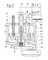
- the central axis 10a of the cylinder PB is rotatably mounted on fixed bearings 10 provided on the frame 11 of the machine.
- the rollers PP and PB are shown, it being understood that the other half is symmetrical.
- the representation of the cylinders is simply shown diagrammatically since they are only represented to display a mode of use of said device. It is simply recalled here that the plate P is a metal plate carrying an engraving of the pattern to be printed, the engraving being covered with ink which will be transferred to the blanket B, itself formed from a plate of resilient materials , fixed or glued on the PB cylinder for the transfer of ink on a printing tape 100.
- each end of the central shaft 14 of the cylinder PP is rotatably mounted in a bearing 12 which can be displaced in principle vertically and which is supported on the upper end of the outlet rod 20 of a pneumatic cylinder 2.
- the node 12 can be undone and bridged by a lever 8 (FIG. 2) or other mechanical part which we will of course take care to make very rigid, like the rest of the assembly described).
- the lower end of the rod 20, the end situated inside the cylindrical enclosure 2a of the jack, is provided with a piston 21 separating the interior volume of the enclosure 2a into two upper 22 and lower 23 sealed chambers.
- a conduit 24, connected to a pressure source (not shown) makes it possible to establish in the upper chamber 22 a pressure b1, while the lower chamber 23 is brought into the open air by means of a conduit 25 with adjustable exhaust (not shown).
- the displacement of the piston 21 downwards, under the effect of the pressure b1 acting on its upper face 21a, is controlled by means of an adjustable stop in the form of a plate or disc 4 located in the lower chamber 23 and capable of be pressed against the underside 21c of the piston 21.
- the disc 4 is engaged, along its central axis, with a threaded rod 5 so that, by rotation of the latter in one direction or the other, one obtains an upward or downward movement of the disc 4.
- the threaded rod 5, located in the extension of the output rod 20 of the jack 2 is mounted in rotation, by means of a rolling bearing 26, on the lower wall, that is to say opposite to that traversed by the output rod 20 of the jack 2.
- the upper end of the threaded rod 5 penetrates inside a hollow lower part of the outlet rod 20, a guide sleeve 27 being interposed between the two rods 20 and 5.
- the rod threaded 5 is rotated at its lower end by means of a servo motor M whose output axis is provided with a toothed wheel 9a engaged with another wheel 9c provided on the threaded rod 5.
- the motor M is mounted, by means of a bracket 28, directly on the cylinder 2a.
- a vertical guide rod 29 that is to say parallel to the outlet rod 20 , connected at each of its ends to the respectively upper and lower walls of the cylinder 2a.
- Each cylinder has a pivot not shown but symbolized by the cross 30, 30 ', by which it is attached to the frame 11.
- a vertical tube 7 is fixed, by its lower end, to the piston 21, while its upper end emerges, in free sliding and sealingly, out of the upper wall of the cylinder 2a.
- a proximity detector or "switch" SW of the position of the piston 21 relative to the support disc 4.
- Another arrangement provides a rod fixed in the disc 4 and penetrating through the tube 7, which has the effect of being able to arrange the switch SW outside of the jack 2, at the end of the tube 7 (better access, same function).
- the information of the detector SW is transmitted by means of an electrical connection 7a.
- the cylinder 2 is provided with adequate seals 2e at each place where it is necessary.
- FIG. 2 shows how, in an offset printing machine, two devices according to the invention can be used simultaneously for controlling the pressure and the distance-between the blanket cylinder PB and the plate cylinder PP and, respectively, the CC counter-cylinder.
- the cylinder CC is used to press, during printing, a printing band 100 which runs, against the cylinder PB. Consequently, it is also necessary, for the safety of the quality of the printing, to control at all times the working pressure and the distance between the two cylinders PB and CC.
- the elements identical to those of FIG. 1 have been designated by the same corresponding reference sign, with the difference that those relating to the device for controlling the cylinder CC have been supplemented by the index '.
- each end of the central shaft 14 of the PP cylinder is rotatably mounted in a bearing 82 located on the end of a horizontal lever 8 which can freely tilt around an axis 81 situated at the other end and mounted on the frame 11 of the machine.
- the outlet rod 20 of the cylinder 2 is connected to a joint 83 located in the middle of the lever 8, so that, when the cylinder 2 is put to pressure b1, the rod 20 is opposed to an upward movement of the lever 8 and therefore at a distance from the cylinder PP relative to the cylinder PB.
- the levers 8, 8 ' will then rest and create compression between PP and PB, and PB and CC, respectively.
- each incremental encoder Ci, C'i will record the exact position of the axis 14 relative to the axis 10a. These values will be loaded onto a diskette assigned to the job in progress.
- the group is ready to start. Note that the second mode will in principle be used because, even for new work, the position of each coder Ci, C'i can be calculated, depending on the format and geometry.
- each end of the central shaft 14 'of the cylinder CC is rotatably mounted in a bearing 82' located around the middle of a horizontal lever 8 'which can freely pivot around an axis 81' located at a first end, l other end being connected by a hinge 83 'at the end of the outlet rod 20' of the jack 2 '. Consequently, when the jack 2 'is put under pressure b'1, its rod 20' tends to pull the cylinder CC upwards so as to press the strip 100 against the cylinder PB.
- an incremental angular encoder Ci of 512 steps / revolution is used.
- the construction is chosen so that, for example, 1 step from the encoder Ci (3.76 ° motor angle) corresponds to 0.00195 mm of displacement of the PP cylinder and only 1 step from the encoder C'i (4, Motor angle 34 °) corresponds to 0.0006 mm of displacement of the CC cylinder, in both cases, for an assured positioning accuracy of the PP cylinders, respectively CC, of 0.01 mm.
- the control panel can be equipped with a push button, a short pulse of which corresponds to 1 encoder step, that is to say approximately 0.001 mm at the "nip" of the PP and PB cylinders and of which another pulse greater than 0.2 sec. corresponds to 9 encoder steps, that is to say approximately 0.01 mm at "nip".
- Correction can also be performed only at one end of the PP cylinder. In this case, however, excessive biasing of the PP cylinder must be avoided. It is possible to limit, for example, this biasing to a maximum of 0.20 mm, ie 179 no difference between the two coders Ci relating to each end of the cylinder PP. This limitation is electrical. After maximum bias, a new asymmetric control is carried out by the two M motors, which maintains the maximum bias without increasing it. The bias can of course be displayed on the machine control panel.
Landscapes
- Engineering & Computer Science (AREA)
- Mechanical Engineering (AREA)
- Inking, Control Or Cleaning Of Printing Machines (AREA)
- Rotary Presses (AREA)
Applications Claiming Priority (2)
| Application Number | Priority Date | Filing Date | Title |
|---|---|---|---|
| CH1419/90 | 1990-04-26 | ||
| CH1419/90A CH683606A5 (fr) | 1990-04-26 | 1990-04-26 | Dispositif avec vérin à précontrainte de contrôle de la pression de travail entre deux cylindres rotatifs coatifs dans une machine de traitement de matière en bande. |
Publications (2)
| Publication Number | Publication Date |
|---|---|
| EP0453981A2 true EP0453981A2 (de) | 1991-10-30 |
| EP0453981A3 EP0453981A3 (en) | 1992-03-25 |
Family
ID=4210015
Family Applications (1)
| Application Number | Title | Priority Date | Filing Date |
|---|---|---|---|
| EP19910106308 Withdrawn EP0453981A3 (en) | 1990-04-26 | 1991-04-19 | Device with prestressing jack for controlling the working pressure between two rotating cylinders in a processing machine for web-, ink-like material or the like |
Country Status (5)
| Country | Link |
|---|---|
| US (1) | US5181468A (de) |
| EP (1) | EP0453981A3 (de) |
| JP (1) | JPH04226355A (de) |
| CA (1) | CA2041199C (de) |
| CH (1) | CH683606A5 (de) |
Families Citing this family (8)
| Publication number | Priority date | Publication date | Assignee | Title |
|---|---|---|---|---|
| JPH0544537U (ja) * | 1991-11-22 | 1993-06-15 | 株式会社小森コーポレーシヨン | 回転体間の接触圧制御装置 |
| ES2166580T3 (es) * | 1998-08-29 | 2002-04-16 | Fischer & Krecke Gmbh & Co | Procedimiento y dispositivo para la prevencion de colisiones en maquinas de imprimir. |
| DE19943031C5 (de) * | 1998-10-27 | 2013-05-02 | Heidelberger Druckmaschinen Ag | Getriebe zum Antrieb einer Druckmaschine |
| DE19963944C1 (de) * | 1999-12-31 | 2001-06-13 | Koenig & Bauer Ag | Verfahren zum Einstellen einer Walze einer Druckmaschine |
| US6543350B2 (en) * | 2000-05-19 | 2003-04-08 | Intelligent Sensing, Inc. | Measurement system to monitor printing contact pressure |
| GB0112321D0 (en) * | 2001-05-21 | 2001-07-11 | Prec Actuation Systems Ltd | Control system |
| DE10305433B4 (de) * | 2003-02-11 | 2007-12-06 | Koenig & Bauer Aktiengesellschaft | Gummizylinder mit Schwingungsdämpfung |
| DE102005045985B4 (de) * | 2005-04-21 | 2012-11-29 | Koenig & Bauer Aktiengesellschaft | Druckeinheit und ein Verfahren zur Einstellung einer Druck-An-Stellung |
Family Cites Families (13)
| Publication number | Priority date | Publication date | Assignee | Title |
|---|---|---|---|---|
| US3958493A (en) * | 1973-08-20 | 1976-05-25 | Tokico Ltd. | Multiple-stage actuating device |
| DE2402769A1 (de) * | 1974-01-22 | 1975-07-24 | Maschf Augsburg Nuernberg Ag | Doppeltwirkender hydraulikzylinder zur zylinderab- und -anstellung fuer druckmaschinen |
| US4169405A (en) * | 1974-04-10 | 1979-10-02 | Fuji Plastic Co. | Control apparatus |
| DE2725033A1 (de) * | 1977-06-03 | 1978-12-14 | Fischer & Krecke Kg | Vorrichtung zur lagerung einer radialen stosskraeften ausgesetzten welle |
| FR2411705A2 (fr) * | 1977-12-13 | 1979-07-13 | Malenge Ets | Machine d'impression rotative |
| DE2822531A1 (de) * | 1978-05-23 | 1979-11-29 | Frankenthal Ag Albert | Tiefdruckmaschine |
| FR2444828A1 (fr) * | 1978-12-18 | 1980-07-18 | Heurtey Metallurgie | Perfectionnements apportes aux verins |
| EP0078496B1 (de) * | 1981-10-30 | 1985-03-27 | Robert Bosch Gmbh | Pneumatikzylinder |
| JPS58142072A (ja) * | 1982-02-15 | 1983-08-23 | Hitachi Ltd | エアシリンダ |
| US4704296A (en) * | 1984-09-28 | 1987-11-03 | Magna-Graphics Corporation | Web coating method and apparatus |
| JPH07115458B2 (ja) * | 1985-03-26 | 1995-12-13 | リョービ株式会社 | オフセット印刷機 |
| DE3640161A1 (de) * | 1985-12-23 | 1987-07-02 | Escher Wyss Gmbh | Vorrichtung zum zueinander positionieren von walzenflaechen |
| JPH0781640B2 (ja) * | 1986-06-23 | 1995-09-06 | エスエムシー株式会社 | 両端停止位置の変更可能な緩衝機構付き空気圧シリンダ |
-
1990
- 1990-04-26 CH CH1419/90A patent/CH683606A5/fr not_active IP Right Cessation
-
1991
- 1991-04-19 EP EP19910106308 patent/EP0453981A3/fr not_active Withdrawn
- 1991-04-23 US US07/689,481 patent/US5181468A/en not_active Expired - Lifetime
- 1991-04-24 JP JP3094401A patent/JPH04226355A/ja active Pending
- 1991-04-25 CA CA002041199A patent/CA2041199C/en not_active Expired - Fee Related
Also Published As
| Publication number | Publication date |
|---|---|
| CA2041199A1 (en) | 1991-10-27 |
| JPH04226355A (ja) | 1992-08-17 |
| US5181468A (en) | 1993-01-26 |
| CA2041199C (en) | 1998-08-18 |
| EP0453981A3 (en) | 1992-03-25 |
| CH683606A5 (fr) | 1994-04-15 |
Similar Documents
| Publication | Publication Date | Title |
|---|---|---|
| EP0453973B1 (de) | Offsetdruckmaschine für veränderliche Formate mit automatischem Laden und Entladen des Zylinders | |
| EP0453981A2 (de) | Vorrichtung mit vorspannendem Kraftzylinder zum Kontrollieren des Bearbeitungsdrucks zwischen zwei rotierenden Zylindern in einer Bearbeitungsmaschine für bahn-, farbförmiges Material oder dergleichen | |
| EP0808701A2 (de) | Drahtsäge | |
| FR2505734A1 (fr) | Presse rotative a bobines | |
| EP0113601B1 (de) | Offset-Rotationsdruckmaschine für variable Formate | |
| FR2518455A1 (fr) | Imprimeuse flexographique | |
| FR2673684A1 (fr) | Ensemble d'un moteur a fluide sous pression a plusieurs cylindrees et d'un frein associe. | |
| FR2490607A1 (fr) | Poste de traitement d'une matiere en bande d'une presse a imprimer, equipe d'un mecanisme de mise en phase a mouvement harmonique | |
| EP0453847A1 (de) | Vorrichtung zur axialen Verschiebung von Walzen in einer Druckmaschine | |
| FR2755057A1 (fr) | Dispositif de mise en appui de rouleaux contre des surfaces rotatives | |
| EP0051037A1 (de) | Verfahren und Vorrichtung zur Positionierung der Farbwerke einer flexographischen Druckmaschine | |
| CH618660A5 (de) | ||
| FR2513608A1 (fr) | Appareil de manutention de feuilles minces de materiau | |
| EP0972639B1 (de) | Vorrichtung zum Einstellen einer flexiblen Druckplatte auf einem Formzylinder | |
| FR2496554A1 (fr) | Mecanisme d'entrainement a inversion du sens de rotation pour les rotatives comprenant un groupe imprimant a dix cylindres | |
| EP1938972B1 (de) | Offset-Druckerpresse mit Regulierung der Schneideklappe und entsprechendes Verfahren | |
| FR2509822A1 (fr) | Dispositif de commande, en particulier pour vehicule moteur sur rails pour fonctionnement au choix par engrenage et adherence, ou adherence seulement, avec mecanisme de subdivision | |
| EP1754599A2 (de) | Druckeinheit mit einem druckan- bzw. druckabstellbaren Gummizylinder und entsprechende Druckmaschine | |
| FR2617122A1 (fr) | Dispositif pour emballer un produit cylindrique dans une feuille | |
| EP0564372B1 (de) | Offsetdruckmaschine | |
| FR2507540A1 (fr) | Dispositif d'impression incorpore a une machine destinee a la fabrication des cigarettes | |
| EP2300231B1 (de) | Druckeinheit mit zwei beabstandungsvorrichtungen und entsprechende verwendung | |
| EP0616889A1 (de) | Offset Druckvorrichtung mit austauschbarer Kassette | |
| FR2741294A1 (fr) | Dispositif de reglage pour des cylindres d'une unite d'impression | |
| EP1525095A2 (de) | Druckmaschine |
Legal Events
| Date | Code | Title | Description |
|---|---|---|---|
| PUAI | Public reference made under article 153(3) epc to a published international application that has entered the european phase |
Free format text: ORIGINAL CODE: 0009012 |
|
| 17P | Request for examination filed |
Effective date: 19910419 |
|
| AK | Designated contracting states |
Kind code of ref document: A2 Designated state(s): AT BE DE DK ES FR GB IT LU NL SE |
|
| PUAL | Search report despatched |
Free format text: ORIGINAL CODE: 0009013 |
|
| AK | Designated contracting states |
Kind code of ref document: A3 Designated state(s): AT BE DE DK ES FR GB IT LU NL SE |
|
| 17Q | First examination report despatched |
Effective date: 19931209 |
|
| STAA | Information on the status of an ep patent application or granted ep patent |
Free format text: STATUS: THE APPLICATION IS DEEMED TO BE WITHDRAWN |
|
| 18D | Application deemed to be withdrawn |
Effective date: 19940621 |