EP0453981A2 - Device with prestressing jack for controlling the working pressure between two rotating cylinders in a processing machine for web-, ink-like material or the like - Google Patents
Device with prestressing jack for controlling the working pressure between two rotating cylinders in a processing machine for web-, ink-like material or the like Download PDFInfo
- Publication number
- EP0453981A2 EP0453981A2 EP91106308A EP91106308A EP0453981A2 EP 0453981 A2 EP0453981 A2 EP 0453981A2 EP 91106308 A EP91106308 A EP 91106308A EP 91106308 A EP91106308 A EP 91106308A EP 0453981 A2 EP0453981 A2 EP 0453981A2
- Authority
- EP
- European Patent Office
- Prior art keywords
- cylinder
- piston
- chamber
- cylinders
- rod
- Prior art date
- Legal status (The legal status is an assumption and is not a legal conclusion. Google has not performed a legal analysis and makes no representation as to the accuracy of the status listed.)
- Withdrawn
Links
Images

Classifications
-
- B—PERFORMING OPERATIONS; TRANSPORTING
- B41—PRINTING; LINING MACHINES; TYPEWRITERS; STAMPS
- B41F—PRINTING MACHINES OR PRESSES
- B41F13/00—Common details of rotary presses or machines
- B41F13/08—Cylinders
- B41F13/24—Cylinder-tripping devices; Cylinder-impression adjustments
- B41F13/34—Cylinder lifting or adjusting devices
- B41F13/40—Cylinder lifting or adjusting devices fluid-pressure operated
-
- B—PERFORMING OPERATIONS; TRANSPORTING
- B41—PRINTING; LINING MACHINES; TYPEWRITERS; STAMPS
- B41F—PRINTING MACHINES OR PRESSES
- B41F33/00—Indicating, counting, warning, control or safety devices
- B41F33/0072—Devices for measuring the pressure between cylinders or bearer rings
Definitions
- the present invention relates to a device for controlling the working pressure between two rotary cylinders in a machine for treating material in the form of a strip, ink or the like.
- An offset, flexography, or rotogravure printing machine comprises at least one pair of rotary or coactive cylinders (or rollers), the force of which tends to push them against each other must be exactly controlled in the course of working or processing a material located at their line (or surface) of contact.
- the material to be worked can be, for example, in the case of an offset machine, either a strip of paper (or cardboard) located between the transfer cylinder (or blanket) and the pressure cylinder (or counter-cylinder), or a thin layer of ink located between the plate cylinder (or plate holder) and the transfer cylinder (or blanket).
- Such pairs of cylinders all have the common characteristic that during work, the two cylinders must be pressed one towards the other in order to achieve not only a working pressure, but in addition a prestress, such so that even a disturbing force higher than the working pressure does not result in the slightest change of center distance.
- This prestressing has been obtained to date by using, for example, running beads produced on the radial periphery of each axial end of the two cylinders.
- the present invention therefore aims to eliminate the need to have recourse to such rolling cords.
- the object of the present invention is also to provide a possible opening of the PP-PB or PB-CC slots from a threshold value corresponding to the preload.
- the present invention also has the function of providing a "protection" for the machine.
- the central axis 10a of the cylinder PB is rotatably mounted on fixed bearings 10 provided on the frame 11 of the machine.
- the rollers PP and PB are shown, it being understood that the other half is symmetrical.
- the representation of the cylinders is simply shown diagrammatically since they are only represented to display a mode of use of said device. It is simply recalled here that the plate P is a metal plate carrying an engraving of the pattern to be printed, the engraving being covered with ink which will be transferred to the blanket B, itself formed from a plate of resilient materials , fixed or glued on the PB cylinder for the transfer of ink on a printing tape 100.
- each end of the central shaft 14 of the cylinder PP is rotatably mounted in a bearing 12 which can be displaced in principle vertically and which is supported on the upper end of the outlet rod 20 of a pneumatic cylinder 2.
- the node 12 can be undone and bridged by a lever 8 (FIG. 2) or other mechanical part which we will of course take care to make very rigid, like the rest of the assembly described).
- the lower end of the rod 20, the end situated inside the cylindrical enclosure 2a of the jack, is provided with a piston 21 separating the interior volume of the enclosure 2a into two upper 22 and lower 23 sealed chambers.
- a conduit 24, connected to a pressure source (not shown) makes it possible to establish in the upper chamber 22 a pressure b1, while the lower chamber 23 is brought into the open air by means of a conduit 25 with adjustable exhaust (not shown).
- the displacement of the piston 21 downwards, under the effect of the pressure b1 acting on its upper face 21a, is controlled by means of an adjustable stop in the form of a plate or disc 4 located in the lower chamber 23 and capable of be pressed against the underside 21c of the piston 21.
- the disc 4 is engaged, along its central axis, with a threaded rod 5 so that, by rotation of the latter in one direction or the other, one obtains an upward or downward movement of the disc 4.
- the threaded rod 5, located in the extension of the output rod 20 of the jack 2 is mounted in rotation, by means of a rolling bearing 26, on the lower wall, that is to say opposite to that traversed by the output rod 20 of the jack 2.
- the upper end of the threaded rod 5 penetrates inside a hollow lower part of the outlet rod 20, a guide sleeve 27 being interposed between the two rods 20 and 5.
- the rod threaded 5 is rotated at its lower end by means of a servo motor M whose output axis is provided with a toothed wheel 9a engaged with another wheel 9c provided on the threaded rod 5.
- the motor M is mounted, by means of a bracket 28, directly on the cylinder 2a.
- a vertical guide rod 29 that is to say parallel to the outlet rod 20 , connected at each of its ends to the respectively upper and lower walls of the cylinder 2a.
- Each cylinder has a pivot not shown but symbolized by the cross 30, 30 ', by which it is attached to the frame 11.
- a vertical tube 7 is fixed, by its lower end, to the piston 21, while its upper end emerges, in free sliding and sealingly, out of the upper wall of the cylinder 2a.
- a proximity detector or "switch" SW of the position of the piston 21 relative to the support disc 4.
- Another arrangement provides a rod fixed in the disc 4 and penetrating through the tube 7, which has the effect of being able to arrange the switch SW outside of the jack 2, at the end of the tube 7 (better access, same function).
- the information of the detector SW is transmitted by means of an electrical connection 7a.
- the cylinder 2 is provided with adequate seals 2e at each place where it is necessary.
- FIG. 2 shows how, in an offset printing machine, two devices according to the invention can be used simultaneously for controlling the pressure and the distance-between the blanket cylinder PB and the plate cylinder PP and, respectively, the CC counter-cylinder.
- the cylinder CC is used to press, during printing, a printing band 100 which runs, against the cylinder PB. Consequently, it is also necessary, for the safety of the quality of the printing, to control at all times the working pressure and the distance between the two cylinders PB and CC.
- the elements identical to those of FIG. 1 have been designated by the same corresponding reference sign, with the difference that those relating to the device for controlling the cylinder CC have been supplemented by the index '.
- each end of the central shaft 14 of the PP cylinder is rotatably mounted in a bearing 82 located on the end of a horizontal lever 8 which can freely tilt around an axis 81 situated at the other end and mounted on the frame 11 of the machine.
- the outlet rod 20 of the cylinder 2 is connected to a joint 83 located in the middle of the lever 8, so that, when the cylinder 2 is put to pressure b1, the rod 20 is opposed to an upward movement of the lever 8 and therefore at a distance from the cylinder PP relative to the cylinder PB.
- the levers 8, 8 ' will then rest and create compression between PP and PB, and PB and CC, respectively.
- each incremental encoder Ci, C'i will record the exact position of the axis 14 relative to the axis 10a. These values will be loaded onto a diskette assigned to the job in progress.
- the group is ready to start. Note that the second mode will in principle be used because, even for new work, the position of each coder Ci, C'i can be calculated, depending on the format and geometry.
- each end of the central shaft 14 'of the cylinder CC is rotatably mounted in a bearing 82' located around the middle of a horizontal lever 8 'which can freely pivot around an axis 81' located at a first end, l other end being connected by a hinge 83 'at the end of the outlet rod 20' of the jack 2 '. Consequently, when the jack 2 'is put under pressure b'1, its rod 20' tends to pull the cylinder CC upwards so as to press the strip 100 against the cylinder PB.
- an incremental angular encoder Ci of 512 steps / revolution is used.
- the construction is chosen so that, for example, 1 step from the encoder Ci (3.76 ° motor angle) corresponds to 0.00195 mm of displacement of the PP cylinder and only 1 step from the encoder C'i (4, Motor angle 34 °) corresponds to 0.0006 mm of displacement of the CC cylinder, in both cases, for an assured positioning accuracy of the PP cylinders, respectively CC, of 0.01 mm.
- the control panel can be equipped with a push button, a short pulse of which corresponds to 1 encoder step, that is to say approximately 0.001 mm at the "nip" of the PP and PB cylinders and of which another pulse greater than 0.2 sec. corresponds to 9 encoder steps, that is to say approximately 0.01 mm at "nip".
- Correction can also be performed only at one end of the PP cylinder. In this case, however, excessive biasing of the PP cylinder must be avoided. It is possible to limit, for example, this biasing to a maximum of 0.20 mm, ie 179 no difference between the two coders Ci relating to each end of the cylinder PP. This limitation is electrical. After maximum bias, a new asymmetric control is carried out by the two M motors, which maintains the maximum bias without increasing it. The bias can of course be displayed on the machine control panel.
Abstract
L'invention concerne un dispositif de contrôle de la pression de travail entre deux cylindres rotatifs (PP, PB) dans une machine de traitement de matière sous forme de bande, de couche d'encre ou similaire, par exemple dans une machine d'impression offset. Le dispositif comprend un vérin pneumatique (2), la tige de sortie (20) du piston (21) agissant sur le positionnement de chaque palier (12) supportant l'extrémité de l'arbre central (14) d'un cylindre (PP). Lorsqu'une chambre (22) du vérin (2) est mise sous pression (b₁), la tige (20) s'oppose à un déplacement du palier (12) qui entraînerait une augmentation de la distance entre les deux cylindres (PP, PB). Une butée (4) fixe, mais réglable en position, s'oppose à un déplacement du palier (12) qui entraînerait une diminution de la distance entre les cylindres (PP, PB).The invention relates to a device for controlling the working pressure between two rotating cylinders (PP, PB) in a machine for processing material in the form of a web, an ink layer or the like, for example in a printing machine offset. The device comprises a pneumatic cylinder (2), the output rod (20) of the piston (21) acting on the positioning of each bearing (12) supporting the end of the central shaft (14) of a cylinder (PP ). When a chamber (22) of the cylinder (2) is pressurized (b₁), the rod (20) opposes a movement of the bearing (12) which would cause an increase in the distance between the two cylinders (PP, PB). A stop (4) fixed, but adjustable in position, opposes a movement of the bearing (12) which would cause a reduction in the distance between the cylinders (PP, PB).
Description
La présente invention concerne un dispositif de contrôle de la pression de travail entre deux cylindres rotatifs dans une machine de traitement de matière sous forme de bande, encre ou similaire.The present invention relates to a device for controlling the working pressure between two rotary cylinders in a machine for treating material in the form of a strip, ink or the like.
Une machine d'impression par offset, par flexographie, ou par héliographie comporte au moins une paire de cylindres (ou rouleaux) rotatifs, ou coactifs, dont la force qui tend à les pousser l'un à l'encontre de l'autre doit être exactement contrôlée dans le cadre du travail ou traitement d'une matière située à leur ligne (ou surface) de contact. La matière à travailler peut être, par exemple, dans le cas d'une machine offset, soit une bande de papier (ou carton) située entre le cylindre report (ou à blanchet) et le cylindre pression (ou contre-cylindre), soit une mince couche d'encre située entre le cylindre cliché (ou porte-plaque) et le cylindre report (ou à blanchet). De telles paires de cylindres ont toutes pour caractéristique commune qu'au cours du travail, les deux cylindres doivent être pressés l'un en direction de l'autre afin de réaliser non seulement une pression de travail, mais en plus une précontrainte, de telle sorte que même une force perturbatrice plus élevée que la pression de travail n'ait pas pour conséquence le moindre changement d'entr'axe. Cette précrontrainte a été obtenue jusqu'à ce jour par recours, par exemple, à des cordons de roulement réalisés sur la périphérie radiale de chaque extrémité axiale des deux cylindres.An offset, flexography, or rotogravure printing machine comprises at least one pair of rotary or coactive cylinders (or rollers), the force of which tends to push them against each other must be exactly controlled in the course of working or processing a material located at their line (or surface) of contact. The material to be worked can be, for example, in the case of an offset machine, either a strip of paper (or cardboard) located between the transfer cylinder (or blanket) and the pressure cylinder (or counter-cylinder), or a thin layer of ink located between the plate cylinder (or plate holder) and the transfer cylinder (or blanket). Such pairs of cylinders all have the common characteristic that during work, the two cylinders must be pressed one towards the other in order to achieve not only a working pressure, but in addition a prestress, such so that even a disturbing force higher than the working pressure does not result in the slightest change of center distance. This prestressing has been obtained to date by using, for example, running beads produced on the radial periphery of each axial end of the two cylinders.
Toutefois, de tels cordons de roulement présentent les inconvénients suivants :
- danger inhérent de grippage dû à une lubrification difficile (propreté);
- cylindre onéreux;
- la pression de travail ne peut être changée que par échange de l'habillage, à moins de mettre les cordons sur excentrique, ce qui est compliqué et cher; de toute façon, et c'est là le désavantage crucial, il faut un arrêt machine pour altérer la pression de travail.
- inherent danger of seizing up due to difficult lubrication (cleanliness);
- expensive cylinder;
- the working pressure can only be changed by exchanging the covering, unless you put the cords on eccentric, which is complicated and expensive; Anyway, and this is the crucial disadvantage, it takes a machine stop to alter the working pressure.
En conséquence, la présente invention a donc pour but d'éliminer la nécessité d'avoir recours à de tels cordons de roulement.Consequently, the present invention therefore aims to eliminate the need to have recourse to such rolling cords.
Un autre aspect négatif de la plupart des arrangements connus est que l'entr'axe PP-PB ou PB-CC est fixe, c'est à dire qu'en cas de surépaisseur accidentelle, les blanchets sont à coup sûr abîmés ainsi qu'éventuellement la plaque et, pour des cas extrêmes, les paliers.Another negative aspect of most of the known arrangements is that the center distance PP-PB or PB-CC is fixed, that is to say that in case of accidental excess thickness, the blankets are undoubtedly damaged as well as possibly the plate and, in extreme cases, the bearings.
Le but de la présente invention est aussi de prévoir une ouverture possible des fentes PP-PB ou PB-CC à partir d'une valeur seuil correspondant à la précontrainte.The object of the present invention is also to provide a possible opening of the PP-PB or PB-CC slots from a threshold value corresponding to the preload.
La présente invention a aussi pour fonction de réaliser une "protection" de la machine.The present invention also has the function of providing a "protection" for the machine.
Ce but est atteint grâce à un dispositif selon la revendication l et à une machine d'impression selon la revendication 8.This object is achieved thanks to a device according to claim 1 and to a printing machine according to
D'autres caractéristiques et avantages de l'invention vont aussi ressortir du mode de réalisation décrit par la suite en référence au dessin annexé dans lequel :
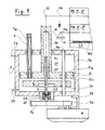
- la figure 1 est une vue en coupe d'un dispositif selon l'invention;
- la figure 2 est un schéma simplifié montrant l'utilisation de deux dispositifs de contrôle selon la figure dans une machine d'impression offset.
- Figure 1 is a sectional view of a device according to the invention;
- Figure 2 is a simplified diagram showing the use of two control devices according to the figure in an offset printing machine.
Dans ce qui suit, les abréviations suivantes sont utilisées :
- p
- = cylindre porteur
- P
- = plaque
- PP
- = ensemble cylindre-porteur et plaque
- B
- = blanchet
- PB
- = ensemble cylindre-porteur et blanchet
- CC
- = contre-cylindre
- p
- = carrier cylinder
- P
- = plate
- PP
- = cylinder-carrier and plate assembly
- B
- = blanket
- PB
- = cylinder-carrier and blanket assembly
- CC
- = counter cylinder
Dans le cas de la figure 1, le dispositif de contrôle est appliqué au réglage de la pression de travail entre la plaque P montée sur le cylindre porte-plaque pP (ensemble = PP) et le blanchet B monté sur son cylindre correspondant pB (ensemble = PB).In the case of FIG. 1, the control device is applied to the adjustment of the working pressure between the plate P mounted on the plate cylinder pP (assembly = PP) and the blanket B mounted on its corresponding cylinder pB (assembly = PB).
A chacune de ses deux extrémités (une seule est représentée dans la figure 1), l'axe central 10a du cylindre PB est monté en rotation sur des paliers fixes 10 prévus sur le bâti 11 de la machine. Dans la figure 1, seule une moitié des rouleaux PP et PB est représentée, étant entendu que l'autre moitié est symétrique. De même, la représentation des cylindres est simplement schématisée puisqu'ils ne sont représentés que pour visualiser un mode d'utilisation dudit dispositif. Il est simplement rappelé ici que la plaque P est une plaque métallique portant une gravure du motif à imprimer, la gravure étant recouverte d'encre qui va être transférée sur le blanchet B, lui-même formé à partir d'une plaque en matériaux résilient, fixée ou collée sur le cylindre PB en vue du transfert de l'encre sur une bande à imprimer 100. En conséquence, il est aisé de comprendre que la pression, avec laquelle la plaque métallique P est pressée ou poussée en direction du blanchet résilient B, aura une grande influence sur le comportement de la couche d'encre comprimée entre les deux faces opposées des cylindres PP et PB. Le dispositif de contrôle en question a pour but de rendre plus aisés et sûrs, en vue de l'impression, la mise en place et le maintien de la pression de travail à travers le contrôle strict de la distance entre les deux cylindres PP et PB.At each of its two ends (only one is shown in Figure 1), the central axis 10a of the cylinder PB is rotatably mounted on
Dans ce but, chaque extrémité de l'arbre central 14 du cylindre PP est montée en rotation dans un palier 12 déplaçable en principe verticalement et prenant appui sur l'extrémité supérieure de la tige de sortie 20 d'un vérin pneumatique 2. (Pour des raisons pratiques, le noeud 12 peut être défait et ponté par un levier 8 (figure 2) ou autre pièce mécanique que l'on aura bien entendu soin de faire très rigide, comme du reste tout l'ensemble décrit). L'extrémité inférieure de la tige 20, extrémité située à l'intérieur de l'enceinte cylindrique 2a du vérin, est munie d'un piston 21 séparant le volume intérieur de l'enceinte 2a en deux chambres étanches supérieure 22 et inférieure 23. Un conduit 24, relié à une source de pression (non représentée) permet d'établir dans la chambre supérieure 22 une pression b₁, alors que la chambre inférieure 23 est mise à l'air libre au moyen d'un conduit 25 à échappement réglable (non représenté). Le déplacement du piston 21 vers le bas, sous l'effet de la pression b₁ agissant sur sa face supérieure 21a, est contrôlé au moyen d'une butée réglable sous forme d'assiette ou de disque 4 situé dans la chambre inférieure 23 et pouvant être mis en appui contre la face inférieure 21c du piston 21. Le disque 4 est en prise, selon son axe central, avec une tige filetée 5 de manière que, par rotation de cette dernière dans un sens ou dans l'autre, on obtienne un déplacement vers le haut ou vers le bas du disque 4. La tige filetée 5, située dans le prolongement de la tige de sortie 20 du vérin 2, est montée en rotation, au moyen d'un palier à roulements 26, sur la paroi inférieure, c'est-à-dire opposée à celle traversée par la tige de sortie 20 du vérin 2.For this purpose, each end of the
Pour avoir un ensemble compact, l'extrémité supérieure de la tige filetée 5 pénètre à l'intérieur d'une partie inférieure creuse de la tige de sortie 20, une douille de guidage 27 étant interposée entre les deux tiges 20 et 5. La tige filetée 5 est entraînée en rotation, à son extrémité inférieure, au moyen d'un servo-moteur M dont l'axe de sortie est muni d'une roue dentée 9a en prise avec une autre roue 9c prévue sur la tige filetée 5. Le moteur M est monté, au moyen d'une équerre 28, directement sur le cylindre 2a. Pour empêcher, à l'intérieur du cylindre 2a, la rotation du piston 21 et du disque 4, ces derniers sont traversés en coulissement libre par une tige de guidage verticale 29, c'est-à-dire parallèle à la tige de sortie 20, reliée en chacune de ses extrémités aux parois respectivement supérieure et inférieure du cylindre 2a. Chaque vérin possède un pivot non représenté mais symbolisé par la croix 30, 30', par lequel il est attaché au bâti 11. Un tube vertical 7 est fixé, par son extrémité inférieure, au piston 21, alors que son extrémité supérieure émerge, en coulissement libre et de façon étanche, hors de la paroi supérieure du cylindre 2a. A l'extrémité inférieure du tube 7 est monté un détecteur de proximité ou "switch" SW de la position du piston 21 par rapport au disque d'appui 4. Un autre arrangement prévoit une tige fixée dans le disque 4 et pénétrant à travers le tube 7, ce qui a pour effet de pouvoir arranger le switch SW à l'extérieur du vérin 2, au bout du tube 7 (meilleur accès, même fonction). Les informations du détecteur SW sont transmises au moyen d'une liaison électrique 7a. Le vérin 2 est muni de joints d'étanchéité adéquats 2e à chaque endroit où cela est nécessaire.To have a compact assembly, the upper end of the threaded
La figure 2 montre de quelle manière, dans une machine d'impression offset, deux dispositifs selon l'invention peuvent être utilisés simultanément pour le contrôle de la pression et de la distance-entre le cylindre porte-blanchet PB et le cylindre porte-plaque PP et, respectivement, le contre-cylindre CC. Il est rappelé ici que le cylindre CC sert à presser, pendant l'impression, une bande à imprimer 100 qui défile, à l'encontre du cylindre PB. En conséquence, il est aussi nécessaire, pour la sûreté de la qualité de l'impression, de contrôler à chaque instant la pression de travail et la distance entre les deux cylindres PB et CC. Dans la figure 2, les éléments identiques à ceux de la figure 1 ont été désignés par le même signe de référence correspondant, avec cette différence que ceux relatifs au dispositif de contrôle du cylindre CC ont été complétés par l'indice '. De plus, chaque dispositif de contrôle selon la figure 2 est muni d'un codeur incrémental Ci, respectivement C'i, dont l'axe de sortie 200, 200' est lié en rotation (aux moyen de deux roues dentées 9i et 9d dans le cas du codeur Ci) à la roue dentée 9c, 9c' de la tige filetée 5, 5'. De même, chaque extrémité de l'arbre central 14 du cylindre PP est monté en rotation dans un palier 82 situé sur l'extrémité d'un levier horizontal 8 pouvant librement basculer autour d'un axe 81 situé à l'autre extrémité et monté sur le bâti 11 de la machine. La tige de sortie 20 du vérin 2 est reliée à une articulation 83 située au milieu du levier 8, de manière à ce que, lorsque le vérin 2 est mis à la pression b₁, la tige 20 s'oppose à un déplacement vers le haut du levier 8 et donc à un éloignement du cylindre PP par rapport au cylindre PB.FIG. 2 shows how, in an offset printing machine, two devices according to the invention can be used simultaneously for controlling the pressure and the distance-between the blanket cylinder PB and the plate cylinder PP and, respectively, the CC counter-cylinder. It is recalled here that the cylinder CC is used to press, during printing, a
Le fonctionnement du dispositif de contrôle peut s'effectuer selon plusieurs modes, dont voici les deux principaux, partant toujours d'une position "ouverte" des leviers 8, 8' (figure 2) :
- pour un nouveau travail par exemple, l'opérateur choisit une pression b, b', selon son expérience, en fonction de la laize, du travail et d'autres critères.
- for a new job for example, the operator chooses a pressure b, b ', according to his experience, according to the width, the job and other criteria.
Les leviers 8, 8' vont alors se mettre en appui et créer une compression entre PP et PB, et PB et CC, respectivement. Les disques 4, 4' sont alors amenés en appui et la rotation correspondante des moteurs M, M' est coupée par les switchs SW, SW' au moment de l'impact des disques 4, 4' avec leur piston 21, 21'. Dès lors, les pressions b, b' passent à une valeur fixe, nettement supérieure (par exemple 6 bar) réalisant ainsi une précontrainte du système.The
Le groupe est prêt au démarrage. L'opérateur peut à tout moment intervenir depuis un pupitre et changer la pression de travail entre PP et PB ou PB et CC, ce qui sera décrit plus tard. A chaque arrêt machine, chaque codeur incrémental Ci, C'i va enregistrer la position exacte de l'axe 14 par rapport à l'axe 10a. Ces valeurs seront chargées sur une disquette attribuée au travail en cours.The group is ready to start. The operator can intervene at any time from a console and change the working pressure between PP and PB or PB and CC, which will be described later. At each machine stop, each incremental encoder Ci, C'i will record the exact position of the
Ceci permet un deuxième mode :
- A partir des axes 82, 82' écartés, les disques d'appui 4, 4' sont envoyés à leurs positions de travail enregistrées, comme décrit ci-dessus, grâce à des moyens électroniques de positionnement utilisant les codeurs incrémentals Ci, C'i. Les pressions b₁, b'₁ sont enclenchées à leur valeur maximale, ayant pour effet d'établir les pressions de travail avec précontrainte entre PP et PB, et PB et CC.
- From the
axes 82, 82 'apart, the support discs 4, 4' are sent to their recorded working positions, as described above, by means of electronic positioning means using the incremental encoders Ci, C'i . The pressures b₁, b'₁ are engaged at their maximum value, having the effect of establishing the working pressures with prestress between PP and PB, and PB and CC.
Le groupe est prêt au démarrage. Notons que le deuxième mode sera en principe utilisé car, même pour un nouveau travail, la position de chaque codeur Ci, C'i peut être calculée, en fonction du format et de la géométrie.The group is ready to start. Note that the second mode will in principle be used because, even for new work, the position of each coder Ci, C'i can be calculated, depending on the format and geometry.
Il est à remarquer que si les parties 5, 20, les suspensions axes 82 et, surtout, les leviers 8 sont bien rigides, le système décrit remplace l'effet des cordons. Ainsi, on a "exporté" la fonction cordon du porteur p à la partie infrastructure, simplifiant ainsi le porteur lui-même.It should be noted that if the
Il est aussi à remarquer que l'opérateur peut à tout moment intervenir depuis le pupitre, à l'arrêt machine ou en marche, et incrémenter ou décrémenter l'entr'axe PP-PB ou PB-CC, ceci :
- des deux côtés simultanément;
- des deux côtés séparément, ce qui provoquera un biaisage - surface de pression conique, - qui sera limité à une valeur seuil. En cas de nouvelle commande asymétrique, l'angle de biaisage est alors maintenu.
- on both sides simultaneously;
- on both sides separately, which will cause a bias - conical pressure surface, - which will be limited to a threshold value. In the event of a new asymmetric control, the bias angle is then maintained.
Dans tous les cas, la rigidité du système est grande.In all cases, the rigidity of the system is high.
Les corrections décrites ci-dessus ont des limites :
- la fermeture de l'entr'axe provoquera une diminution de la précontrainte entre le disque 4, 4' et le
piston 21, 21' et finalement un décollement du disque 4, 4', ce qui sera intercepté par les switchs SW, SW'. L'entr'axe sera alors rouvert automatiquement d'une valeur assurant de nouveau la précontrainte, donc stabilité du système. - l'ouverture de l'entr'axe provoquera finalement un contact limite et une déterioration, puis, une disparition de l'impression.
- the closing of the center distance will cause a reduction in the preload between the disc 4, 4 'and the
piston 21, 21' and finally a detachment of the disc 4, 4 ', which will be intercepted by the switches SW, SW' . The center distance will then be automatically reopened with a value again ensuring the preload, therefore system stability. - the opening of the center distance will eventually cause limited contact and deterioration, then, disappearance of the impression.
Notons que la zone de pression usuelle se trouve centrée entre ces deux extrêmes, assurant donc la possibilité de larges variations de la pression de travail en plus ou en moins.Note that the usual pressure zone is centered between these two extremes, thus ensuring the possibility of large variations in working pressure in more or less.
Etant donné le poids relativement important du cylindre PP, il est apparu utile de relier aussi le point d'articulation 83 à la tige de sortie 400 d'un vérin d'appoint Va, la liaison étant telle que, lorsqu'une chambre de ce vérin est mise à la pression a₁, la tige 400 reprend une partie au moins du poids du cylindre PP pour éviter un écrasement excessif du blanchet B; par contre, lorsqu'une autre chambre du vérin Va est mise à une pression a₂, la tige 400 pousse le cylindre PP en direction du cylindre PB. La pression a₂ augmente l'effet de précontrainte.Given the relatively large weight of the cylinder PP, it appeared useful to also connect the
La position du second vérin 2' est inversée par rapport à celle du vérin 2, c'est-à-dire que la tige de sortie 20' est dirigée vers le bas. Chaque extrémité de l'arbre central 14' du cylindre CC est montée en rotation dans un palier 82' situé aux environs du milieu d'un levier horizontal 8' pouvant librement pivoter autour d'un axe 81' situé à une première extrémité, l'autre extrémité étant reliée par une articulation 83' à l'extrémité de la tige de sortie 20' du vérin 2'. En conséquence, lorsque le vérin 2' est mis à la pression b'₁, sa tige 20' tend à tirer le cylindre CC vers le haut de manière à presser la bande 100 à l'encontre du cylindre PB.The position of the second cylinder 2 'is reversed relative to that of the
Pour satisfaire aux conditions de précision souhaitées pour le positionnement du cylindre PP, un codeur angulaire incrémental Ci de 512 pas/tour est utilisé. La construction est choisie pour que, par exemple, à 1 pas du codeur Ci (3,76° d'angle moteur) corresponde 0,00195 mm de déplacement du cylindre PP et qu'à 1 pas du codeur C'i (4,34° d'angle moteur) corresponde 0,0006 mm de déplacement du cylindre CC, dans les deux cas, pour une précision de positionnement assurée des cylindres PP, respectivement CC, de 0,01 mm.To meet the precision conditions desired for the positioning of the PP cylinder, an incremental angular encoder Ci of 512 steps / revolution is used. The construction is chosen so that, for example, 1 step from the encoder Ci (3.76 ° motor angle) corresponds to 0.00195 mm of displacement of the PP cylinder and only 1 step from the encoder C'i (4, Motor angle 34 °) corresponds to 0.0006 mm of displacement of the CC cylinder, in both cases, for an assured positioning accuracy of the PP cylinders, respectively CC, of 0.01 mm.
Lorsque la machine est en marche, il est possible de varier la compression du blanchet B par correction de la position du cylindre PP. Lors de cette correction, le moteur M doit agir à l'encontre de la pression de précontrainte. Dans ce but, le tableau de commande peut être équipé d'un bouton poussoir dont une courte impulsion correspond à 1 pas codeur, c'est-à-dire environ à 0,001 mm au niveau du "nip" des cylindres PP et PB et dont une autre impulsion plus grande que 0,2 sec. correspond à 9 pas codeur, c'est-à-dire à environ 0,01 mm au "nip".When the machine is running, it is possible to vary the compression of the blanket B by correcting the position of the cylinder PP. During this correction, the motor M must act against the prestressing pressure. For this purpose, the control panel can be equipped with a push button, a short pulse of which corresponds to 1 encoder step, that is to say approximately 0.001 mm at the "nip" of the PP and PB cylinders and of which another pulse greater than 0.2 sec. corresponds to 9 encoder steps, that is to say approximately 0.01 mm at "nip".
La correction peut aussi être exécutée seulement à une seule extrémité du cylindre PP. Dans ce cas, il faut toutefois éviter un biaisage excessif du cylindre PP. Il est possible de limiter, par exemple, ce biaisage à 0,20 mm maximum, soit 179 pas de différence entre les deux codeurs Ci relatifs à chaque extrémité du cylindre PP. Cette limitation est électrique. Après un biaisage maximum, une nouvelle commande asymétrique est réalisée par les deux moteurs M, ce qui maintient le biaisage maximal sans l'augmenter. Le biaisage peut être bien sûr affiché sur le pupitre de commande de la machine.Correction can also be performed only at one end of the PP cylinder. In this case, however, excessive biasing of the PP cylinder must be avoided. It is possible to limit, for example, this biasing to a maximum of 0.20 mm, ie 179 no difference between the two coders Ci relating to each end of the cylinder PP. This limitation is electrical. After maximum bias, a new asymmetric control is carried out by the two M motors, which maintains the maximum bias without increasing it. The bias can of course be displayed on the machine control panel.
Il est évident que tous les groupes relatifs aux différentes couleurs d'une machine d'impression peuvent avoir leur cylindres PP et CC munis de tels dispositifs de contrôle avec vérins à précontrainte. Dans ce cas, une seule valeur de consigne, relative soit au vérin PP soit au vérin CC, peut être utilisée pour tous les groupes simultanément pour leur mise en pression et correction simultanée.It is obvious that all the groups relating to the different colors of a printing machine can have their PP and CC cylinders provided with such control devices with preload cylinders. In this case, a single setpoint value, relating either to the PP cylinder or to the CC cylinder, can be used for all the groups simultaneously for their pressurization and simultaneous correction.
Il est également possible d'équiper les rouleaux toucheurs d'un tel dispositif; sa taille serait alors réduite en conséquence.It is also possible to equip the touch rollers with such a device; its size would then be reduced accordingly.
Claims (11)
Applications Claiming Priority (2)
| Application Number | Priority Date | Filing Date | Title |
|---|---|---|---|
| CH1419/90A CH683606A5 (en) | 1990-04-26 | 1990-04-26 | Device with cylinder preload control the working pressure between two coatifs rotating cylinders in a web material-processing machine. |
| CH1419/90 | 1990-04-26 |
Publications (2)
| Publication Number | Publication Date |
|---|---|
| EP0453981A2 true EP0453981A2 (en) | 1991-10-30 |
| EP0453981A3 EP0453981A3 (en) | 1992-03-25 |
Family
ID=4210015
Family Applications (1)
| Application Number | Title | Priority Date | Filing Date |
|---|---|---|---|
| EP19910106308 Withdrawn EP0453981A3 (en) | 1990-04-26 | 1991-04-19 | Device with prestressing jack for controlling the working pressure between two rotating cylinders in a processing machine for web-, ink-like material or the like |
Country Status (5)
| Country | Link |
|---|---|
| US (1) | US5181468A (en) |
| EP (1) | EP0453981A3 (en) |
| JP (1) | JPH04226355A (en) |
| CA (1) | CA2041199C (en) |
| CH (1) | CH683606A5 (en) |
Families Citing this family (8)
| Publication number | Priority date | Publication date | Assignee | Title |
|---|---|---|---|---|
| JPH0544537U (en) * | 1991-11-22 | 1993-06-15 | 株式会社小森コーポレーシヨン | Contact pressure control device between rotating bodies |
| DE59802253D1 (en) * | 1998-08-29 | 2002-01-10 | Fischer & Krecke Gmbh & Co | Method and device for collision monitoring in printing machines |
| DE19943031C5 (en) * | 1998-10-27 | 2013-05-02 | Heidelberger Druckmaschinen Ag | Transmission for driving a printing press |
| DE19963944C1 (en) * | 1999-12-31 | 2001-06-13 | Koenig & Bauer Ag | Method to adjust cylinders of printing machine; involves moving abutment to limit stroke of axle holder for adjustable cylinder at space from base plate and applying adjusting and holding forces |
| US6543350B2 (en) * | 2000-05-19 | 2003-04-08 | Intelligent Sensing, Inc. | Measurement system to monitor printing contact pressure |
| GB0112321D0 (en) * | 2001-05-21 | 2001-07-11 | Prec Actuation Systems Ltd | Control system |
| DE10305433B4 (en) * | 2003-02-11 | 2007-12-06 | Koenig & Bauer Aktiengesellschaft | Rubber cylinder with vibration damping |
| DE102005045985B4 (en) * | 2005-04-21 | 2012-11-29 | Koenig & Bauer Aktiengesellschaft | Printing unit and a method for setting a print on position |
Citations (6)
| Publication number | Priority date | Publication date | Assignee | Title |
|---|---|---|---|---|
| FR2258267A1 (en) * | 1974-01-22 | 1975-08-18 | Maschf Augsburg Nuernberg Ag | Double acting hydraulic cylinder for printing machine - is used to engage and disengage printing cylinder and has piston movement limiting stop |
| DE2822531A1 (en) * | 1978-05-23 | 1979-11-29 | Frankenthal Ag Albert | Photogravure printing press form cylinder pressure system - has ram adjusted yoke shoes supported by screw and nut drive |
| FR2444828A1 (en) * | 1978-12-18 | 1980-07-18 | Heurtey Metallurgie | Control system for ram positioning - has sliding stop worked by motor driven screw and incorporating shock absorber |
| JPS58142072A (en) * | 1982-02-15 | 1983-08-23 | Hitachi Ltd | Air cylinder |
| US4704296A (en) * | 1984-09-28 | 1987-11-03 | Magna-Graphics Corporation | Web coating method and apparatus |
| JPS636270A (en) * | 1986-06-23 | 1988-01-12 | Smc Corp | Pneumatic cylinder capable of altering double end stopping position |
Family Cites Families (7)
| Publication number | Priority date | Publication date | Assignee | Title |
|---|---|---|---|---|
| US3958493A (en) * | 1973-08-20 | 1976-05-25 | Tokico Ltd. | Multiple-stage actuating device |
| US4169405A (en) * | 1974-04-10 | 1979-10-02 | Fuji Plastic Co. | Control apparatus |
| DE2725033A1 (en) * | 1977-06-03 | 1978-12-14 | Fischer & Krecke Kg | DEVICE FOR SUPPORTING A SHAFT EXPOSED TO RADIAL SHOCK FORCES |
| FR2411705A2 (en) * | 1977-12-13 | 1979-07-13 | Malenge Ets | Multicylinder rotary printing machine - has hydraulic cylinders to raise and lower counter rollers mounted on hinged arms |
| EP0078496B1 (en) * | 1981-10-30 | 1985-03-27 | Robert Bosch Gmbh | Pneumatic cylinder |
| JPH07115458B2 (en) * | 1985-03-26 | 1995-12-13 | リョービ株式会社 | Offset printing machine |
| DE3640161A1 (en) * | 1985-12-23 | 1987-07-02 | Escher Wyss Gmbh | Apparatus for the relative positioning of roll surfaces |
-
1990
- 1990-04-26 CH CH1419/90A patent/CH683606A5/en not_active IP Right Cessation
-
1991
- 1991-04-19 EP EP19910106308 patent/EP0453981A3/en not_active Withdrawn
- 1991-04-23 US US07/689,481 patent/US5181468A/en not_active Expired - Lifetime
- 1991-04-24 JP JP3094401A patent/JPH04226355A/en active Pending
- 1991-04-25 CA CA002041199A patent/CA2041199C/en not_active Expired - Fee Related
Patent Citations (6)
| Publication number | Priority date | Publication date | Assignee | Title |
|---|---|---|---|---|
| FR2258267A1 (en) * | 1974-01-22 | 1975-08-18 | Maschf Augsburg Nuernberg Ag | Double acting hydraulic cylinder for printing machine - is used to engage and disengage printing cylinder and has piston movement limiting stop |
| DE2822531A1 (en) * | 1978-05-23 | 1979-11-29 | Frankenthal Ag Albert | Photogravure printing press form cylinder pressure system - has ram adjusted yoke shoes supported by screw and nut drive |
| FR2444828A1 (en) * | 1978-12-18 | 1980-07-18 | Heurtey Metallurgie | Control system for ram positioning - has sliding stop worked by motor driven screw and incorporating shock absorber |
| JPS58142072A (en) * | 1982-02-15 | 1983-08-23 | Hitachi Ltd | Air cylinder |
| US4704296A (en) * | 1984-09-28 | 1987-11-03 | Magna-Graphics Corporation | Web coating method and apparatus |
| JPS636270A (en) * | 1986-06-23 | 1988-01-12 | Smc Corp | Pneumatic cylinder capable of altering double end stopping position |
Non-Patent Citations (3)
| Title |
|---|
| HYDRAULIC PNEUMATIC POWER. vol. 17, no. 196, Avril 1971, MORDEN GB pages 186 - 191; CONSTANT A.E.: 'DESIGN ASPECTS OF HYDRAULIC AND PNEUMATIC CYLINDERS' * |
| PATENT ABSTRACTS OF JAPAN vol. 12, no. 201 (M-707)10 Juin 1988 & JP-A-63 006 270 ( SMC CORP. ) 12 Janvier 1988 * |
| PATENT ABSTRACTS OF JAPAN vol. 7, no. 261 (M-257)(1406) 19 Novembre 1983 & JP-A-58 142 072 ( HITACHI SEISAKUSHO K.K. ) 23 Août 1983 * |
Also Published As
| Publication number | Publication date |
|---|---|
| CH683606A5 (en) | 1994-04-15 |
| US5181468A (en) | 1993-01-26 |
| CA2041199A1 (en) | 1991-10-27 |
| CA2041199C (en) | 1998-08-18 |
| JPH04226355A (en) | 1992-08-17 |
| EP0453981A3 (en) | 1992-03-25 |
Similar Documents
| Publication | Publication Date | Title |
|---|---|---|
| EP0453973B1 (en) | Offset printing machine for variable repeat distance with automatic loading and unloading of cylinders | |
| EP0453981A2 (en) | Device with prestressing jack for controlling the working pressure between two rotating cylinders in a processing machine for web-, ink-like material or the like | |
| EP1754599B1 (en) | Printing unit with blanket cylinder movable between a throw-on and a throw-off position and corresponding printing press | |
| EP0438328A1 (en) | Apparatus for assembling by pressing laminated glass | |
| FR2735419A1 (en) | DIRECT DRIVE DEVICE FOR A PRINTING MACHINE | |
| FR2505734A1 (en) | ROTARY PRESS WITH COILS | |
| EP0113601B1 (en) | Variable-size rotary offset printing machine | |
| FR2518455A1 (en) | FLEXOGRAPHIC PRINTER | |
| FR2673684A1 (en) | ASSEMBLY OF A MULTI-CYLINDER PRESSURIZED FLUID ENGINE AND ASSOCIATED BRAKE. | |
| FR2490607A1 (en) | PROCESSING STATION OF A STRIP MATERIAL FOR A PRESS TO BE PRINTED, EQUIPPED WITH A HARMONIC MOTION MOVEMENT MECHANISM | |
| EP0453847A1 (en) | Axially reciprocating device for rollers in a printing machine | |
| FR2755057A1 (en) | DEVICE FOR SUPPORTING ROLLERS AGAINST ROTATING SURFACES | |
| EP1800863B1 (en) | Inking device and corresponding adjustment method | |
| EP0051037A1 (en) | Process and device for positioning the inking stations of a flexographic printing machine | |
| CH618660A5 (en) | ||
| FR2496554A1 (en) | REVERSING ROTATIONAL DIRECTION DRIVE MECHANISM COMPRISING A TEN CYLINDER PRINTING UNIT | |
| FR2509822A1 (en) | CONTROL DEVICE, IN PARTICULAR FOR MOTOR VEHICLE ON RAILS FOR GEAR CHOICE AND ADHESION OPERATION, OR ADHESION ONLY, WITH SUBDIVISION MECHANISM | |
| EP1938972A1 (en) | Offset printing press with adjustment of the cut-off register and corresponding method | |
| FR2617122A1 (en) | Device for packaging a cylindrical product in a sheet | |
| FR2507540A1 (en) | PRINTING DEVICE INCORPORATED IN A MACHINE INTENDED FOR THE MANUFACTURE OF CIGARETTES | |
| EP2300231B1 (en) | Printing unit with two spacer devices and corresponding use | |
| FR2702996A1 (en) | Offset cassette printing device. | |
| FR2467169A1 (en) | Tower crane with permanent balancing - has base supports with monitors to measure side loads and control counter-balance weight | |
| FR2741294A1 (en) | ADJUSTING DEVICE FOR CYLINDERS OF A PRINTING UNIT | |
| WO2004012941A2 (en) | Printing machine |
Legal Events
| Date | Code | Title | Description |
|---|---|---|---|
| PUAI | Public reference made under article 153(3) epc to a published international application that has entered the european phase |
Free format text: ORIGINAL CODE: 0009012 |
|
| 17P | Request for examination filed |
Effective date: 19910419 |
|
| AK | Designated contracting states |
Kind code of ref document: A2 Designated state(s): AT BE DE DK ES FR GB IT LU NL SE |
|
| PUAL | Search report despatched |
Free format text: ORIGINAL CODE: 0009013 |
|
| AK | Designated contracting states |
Kind code of ref document: A3 Designated state(s): AT BE DE DK ES FR GB IT LU NL SE |
|
| 17Q | First examination report despatched |
Effective date: 19931209 |
|
| STAA | Information on the status of an ep patent application or granted ep patent |
Free format text: STATUS: THE APPLICATION IS DEEMED TO BE WITHDRAWN |
|
| 18D | Application deemed to be withdrawn |
Effective date: 19940621 |