EP0451990A2 - Verfahren zum Wählen einer Frequenz für einen RDS-Empfänger - Google Patents
Verfahren zum Wählen einer Frequenz für einen RDS-Empfänger Download PDFInfo
- Publication number
- EP0451990A2 EP0451990A2 EP91302686A EP91302686A EP0451990A2 EP 0451990 A2 EP0451990 A2 EP 0451990A2 EP 91302686 A EP91302686 A EP 91302686A EP 91302686 A EP91302686 A EP 91302686A EP 0451990 A2 EP0451990 A2 EP 0451990A2
- Authority
- EP
- European Patent Office
- Prior art keywords
- data
- frequency
- station
- program
- received
- Prior art date
- Legal status (The legal status is an assumption and is not a legal conclusion. Google has not performed a legal analysis and makes no representation as to the accuracy of the status listed.)
- Granted
Links
- 238000000034 method Methods 0.000 title claims abstract description 36
- 230000004044 response Effects 0.000 claims description 6
- 238000010408 sweeping Methods 0.000 claims description 6
- 238000001514 detection method Methods 0.000 description 11
- 238000012545 processing Methods 0.000 description 11
- 230000006870 function Effects 0.000 description 8
- 238000010586 diagram Methods 0.000 description 5
- 238000012544 monitoring process Methods 0.000 description 3
- 230000005540 biological transmission Effects 0.000 description 2
- 238000010276 construction Methods 0.000 description 2
- 230000005236 sound signal Effects 0.000 description 2
- 238000007796 conventional method Methods 0.000 description 1
- 238000012937 correction Methods 0.000 description 1
- 230000005684 electric field Effects 0.000 description 1
Images

Classifications
-
- H—ELECTRICITY
- H03—ELECTRONIC CIRCUITRY
- H03J—TUNING RESONANT CIRCUITS; SELECTING RESONANT CIRCUITS
- H03J1/00—Details of adjusting, driving, indicating, or mechanical control arrangements for resonant circuits in general
- H03J1/0008—Details of adjusting, driving, indicating, or mechanical control arrangements for resonant circuits in general using a central processing unit, e.g. a microprocessor
- H03J1/0058—Details of adjusting, driving, indicating, or mechanical control arrangements for resonant circuits in general using a central processing unit, e.g. a microprocessor provided with channel identification means
- H03J1/0066—Details of adjusting, driving, indicating, or mechanical control arrangements for resonant circuits in general using a central processing unit, e.g. a microprocessor provided with channel identification means with means for analysing the received signal strength
Definitions
- the present invention relates to a receiving frequency selecting method in a receiver for a radio data system (hereinafter, referred to as an RDS receiver).
- RDS radio data system
- broadcast-related information such as information regarding the content of the program and the like is multiplex modulated as data for the transmission.
- the transmitted data is demodulated and a desired program content can be selected on the basis of the demodulated data, thereby enabling the broadcasting service of the program to be provided to a radio listener.
- a signal of 57 kHz as a third order harmonic of a stereo pilot signal of 19 kHz is used as a subcarrier in a band out of the frequency band of a frequency modulated wave.
- the subcarrier is amplitude modulated by a data signal which has been filtered and biphase encoded and which indicates information regarding the broadcast such as program content or the like.
- the amplitude modulated subcarrier is used as a radio data signal and is frequency modulated into the main carrier and is broadcast.
- the standard for this broadcasting method has been proposed by the European Broadcasting Union (EBU).
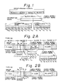
- the radio data signal is repeatedly transmitted by a multiplex transmission, in group unitseach comprising 104 bits.
- One group is constituted by four blocks each consisting of 26 bits. Each block comprises an information word of 16 bits and a check word of 10 bits.
- the groups are classified into sixteen types 0 to 15 in accordance with the content by using four bits. Two versions A and B are defined foreach of the types (0 to 15).
- Figs. 2A and 2B respectively show the format of the groups type 0A and type 0B.
- program ID data hereinafter, referred to as PI data
- various codes comprising a group type code, a version code (B0), a traffic information broadcasting station ID (TP) code, a program content ID (PTY) code, and the like are arranged in the block 2
- station frequency data hereinafter, abbreviated to AF data
- PS data broadcasting station name data
- the respective data are arranged in the blocks 1, 2, and 4 in a manner similar to the type 0A group except that only the content in the block 3 differs from that in the case of the type 0A group and the PI data is arranged in the block 3. That is, the AF data of the network stationsis transmitted by only the type 0A group and the PS data is transmitted by both of the groups of the types 0A and 0B.
- the AF data of the network stations broadcasting the same program as that of the broadcasting station which is currently being received is also included in the radio data signal of the type 0A group. Therefore, upon reception, the AF data and the PI data which have been obtained by the demodulation are taken and stored as an AF list. For instance, if a receiving intensity of the broadcasting station which is currently being received deteriorates due to a disturbance such as a multi-path interference or the like, another station in the same network station group is selected on the basis of the AF list which has previously been stored. Further, a check is made to see if the program received by the AF list is correct or not by what is called a PI check to compare and check for coincidence of the PI data. By what is called a network following function as mentioned above, the same program can be always listened to in a good receiving state without being influenced by the disturbances.
- a timer of a predetermined time is set and the PI data obtained from the broadcasting wave of such a station is taken and, after the time-up of the timer, the PI data is checked.
- the PI check is performed after the elapse of a predetermined time after the existence of the same network station had been detected as mentioned above, it is possible to cope with various cases of field conditions.
- a muting process is necessarily executed for the predetermined time. This means that a time period in which the user is disturbed becomes long by an amount corresponding to the period of such a muting process.
- the receiving station In the network following operation, in the case where the existence of a same network station in a good receiving state cannot be detected from the same network station group, hitherto, the receiving station is returned to the broadcasting station (original receiving station) which was being received at first (for instance, reference is directed to Japanese Patent Application Laid Open No. 1-151319). However, if the receiving is merely returned to the original receiving station, the receiving state with a low receiving signal intensity will forcibly be set. In the case where the listener wishes to subsequently listen to the broadcasting of the same program in a good receiving state, a broadcasting station which broadcasts the same program must be searched by a manual tuning (station selection) operation.
- an object of the invention to provide a receiving frequency selecting method in an RDS receiver, in which by enabling a PI check to be performed in a short time, a disturbance associated with a muting process upon PI check is reduced.
- Another object of the invention is to provide a receiving frequency selecting method in an RDS receiver, in which even in the case where the existence of a same network station is not detected through the network following operation, a broadcasting station of the same program can be automatically searched.
- a receiving frequency selecting method in an RDS receiver which can receive an RDS broadcasting wave on which a plurality of AF data and PI data of a same network station group are superimposed, in which a receiving frequency is switched from a current receiving frequency to a frequency of another same network station which is given by one of the plurality of AF data
- the method comprises: a first step of holding the PI data which is obtained from a broadcasting wave of the present receiving frequency in response to a command; a second step of tuning the receiver to another frequency based on the plurality of AF data detecting the existence of a received station; a third step of taking in the PI data obtained from the broadcasting wave of the received station detected in the second step; a fourth step of detecting that a predetermined time has elapsed from a time point when the existence of the received station is detected in the second step or that the same PI data has been taken in a plural number of times in the third step; and a fifth step of comparing
- the PI data of the currently received station is held in response to a command and, when the existence of a received station based on the AF list is detected and the same PI data is taken in a plural number of times as PI data which is derived from the broadcasting wave of the received station, the PI check is executed even if a predetermined time has not elapsed from a time point when the existence of the received station is detected.
- a receiving frequency selecting method in an RDS receiver which can receive an RDS broadcasting wave in which a plurality of AF data and PI data of a same network station group are superimposed, wherein the method comprises: a first step of holding the PI data obtained from a broadcasting wave of a current receiving frequency in response to a command; a second step in which when the existence of a same network station whose reception signal level is equal to or higher than a set level and and in which the PI data obtained from the received broadcasting wave coincides with the PI data held in the first step is detected from the same netw station group which are given by the plurality of AF data, the frequency of such a same network station is as a new receiving frequency; and a third step in which when the existence of the same network station cannot be detected in the second step, if the existence of a received station whose reception signal level is equal to or higher than a set level and in which the PI data obtained from the received broadcasting wave coincides with the PI
- the PI data of the originally received station is previously held, and in the case where the existence of the same network station cannot be detected by the network following function, when the existence of a received station whose reception signal level is equal to or higher than a set level and in which the received PI data coincides with the holding PI data is detected while executing a frequency sweeping operation, the frequency of such a received station is set as a new receiving frequency.
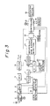
- Fig. 3 is a block diagram showing an outline of a fundamental construction of an RDS receiver to which a receiving frequency selecting method according to the invention is applied.
- an FM multiplexed broadcasting wave received by an antenna 1 is supplied to a front-end 2, by which a desired station is selected and the broadcasting wave of the selected station is converted into an intermediate frequency (IF).
- the IF signal is supplied to an FM detector 4 through an IF amplifier 3.
- the front-end 2 uses, for instance, a PLL synthesizer system using a PLL circuit including a programmable frequency divider and executes a station selecting operation by a method whereby a frequency dividing ratio of the programmable frequency divider is controlled by a controller 13, which will be explained hereinlater.
- a detection output of the FM detector 4 is supplied to an MPX (multiplex) demodulator 5 and is separated into audio signals of the L (left) and R (right) channels in the case of the stereophonic broadcasting.
- the audio signals are supplied to a muting circuit 18, so that reproduction audio outputs are derived.
- the muting circuit 18 is on/off controlled by the controller 13.
- the detection output of the FM detector 4 is transmitted through a filter 6, so that a subcarrier of 57 kHz which has been amplitude modulated by a biphase encoded data signal, that is, a radio data signal is extracted and is demodulated by a PLL circuit 7.
- the demodulation output is supplied to a digital (D) PLL circuit 8 and a decoder 9.
- the D-PLL circuit 8 produces a clock for data demodulation on the basis of the demodulation output of the PLL circuit 7.
- the biphase encoded data signal as a demodulation output of the PLL circuit 7 is decoded synchronously with the clock generated from the D-PLL circuit 8.
- a locking state detecting circuit 10 detects locking/unlocking states of the D-PLL circuit 8. Locking ranges of the PLL circuit 7 and D-PLL circuit 8 are switched by a detection output of the locking state detecting circuit 10.
- output data of the decoder 9 has a group unit of 104 bits comprising four blocks each consisting of 26 bits and is sequentially supplied to a group/block sync & error detecting circuit 11.
- a group/block sync & error detecting circuit 11 synchronization of the group and the block is attained on the basis of an offset word of 10 bits assigned to each check word of 10 bits of each block.
- An error of an information word of 16 bits is detected on the basis of the check word.
- the error detected data is error corrected by an error correction circuit 12 at the next stage and, thereafter, the corrected data is supplied to the controller 13.
- the controller 13 is constituted by a microcomputer.
- the code information of each block in the radio data which is sequentially supplied on a group unit basis, that is, the radio data information such as PI data, AF data, PS data, and the like regarding the program content of the broadcasting station which is currently being received is taken in and stored into a memory 14.
- the controller 13 executes the network following function by controlling the frequency dividing ratio of the programmable frequency divider (not shown) of the PLL circuit constituting a part of the front-end 2 on the basis of a station selecting command from an operating section 15.
- a level detecting circuit 16 to detect a reception signal level (electric field intensity) on the basis of an IF signal level in the IF amplifier 3 is also provided.
- a station detecting circuit 17 for detecting a receiving station in the case where the IF signal level in the IF amplifier 3 is equal to or higher than a predetermined level and where a detection output having what are called S-curve characteristics in the FM detector 4 lies within a predetermined level range and for generating a station detection signal.
- the reception signal level detected by the level detecting circuit 16 and the station detection signal which is generated from the station detecting circuit 17 are supplied to the controller 13.
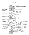
- the above processing routine is called for execution by a switching command which is generated when a receiving intensity of the broadcasting station which is currently being received has deteriorated due to a disturbance such as a multi-path interference or the like.
- the AF data obtained by demodulating the received broadcasting wave has been taken in and an AF list of the same network stations as the broadcasting station which is currently being received has already been made and stored in the memory 14.
- the processor first fetches the AF data and PI data of the broadcasting wave which is currently being received and stores and holds into predetermined areas in the memory 14 (step S1).
- the muting circuit 18 is turned on to execute an audio muting process (step S2).
- one AF data in the list is read out of the memory 14 on the basis of the AF list stored in the memory 14 (step S3).
- the read AF data is supplied to a PLL circuit (not shown) in the front-end 2 (step S4).
- a PLL timer of a time necessary to lock the PLL circuit is set (step S5).
- the AF data supplied to the PLL circuit is set into the programmable frequency divider in the PLL circuit. For a period of time until the PLL timer times up, the receiving frequency is changed from the current receiving frequency to a frequency of another network station.
- step S6 the processor checks that a station is being received by monitoring a station detection signal output from the station detecting circuit 17 (step S7). If the existence of a received station is detected, a PI timer of a predetermined time is set (step S8). After that, the PI data of the receiving station is taken in (step S9). The processor subsequently checks to see if the same PI data has been taken in a plurality of number of times (for example, two times) or not (step S10). If the same PI data has been taken in a plurality of number of times, a PI flag is set (step S11). A check is then made to see if the PI timer has timed up or not (step S12). If it is determined in step S10 that the same PI data is not taken a plurality of number of times, the processing routine directly advances to step S12.
- step S12 determines whether the PI timer has timed out. If it is determined in step S12 that the PI timer has timed out, the processor executes the PI check to see if the PI data taken currently coincides with the PI data held in step S1 or not (step S13). If it is detected that the PI timer has not yet timed out, a check is made to see if the PI flag has been set or not (in other words, to see if the same PI data has been taken in a plurality of number of times in step S10 or not) (step S14). If the PI flag has been set, step S13 follows. If the PI flag is not set, the processing routine is returned to step S9.
- step S13 If it is determined that both of the PI data coincide as a result of the PI check in step S13, the processor turns off the muting circuit 18, thereby canceling the audio muting (step S15).
- the frequency of the station presently being received is set as a new receiving frequency and the same PI station in the same network station group has been selected.
- step S16 the processor discriminates whether the checks regarding the existence of the received station and the PI checks have been finished with respect to all of the AF lists or not (step S16). If all of the above checks are not completed, the processing routine is returned to step S3 and the foregoing processes are repeated. If the checks for all of the AF lists have been finished, the processor reads out the original AF data held in step S1 (step S17) and subsequently supplies the read AF data to the PLL circuit (step S18). Further, the PLL timer is set (step S19). After the PLL timer has timed up (step S20), the processing routine advances to step S15 and the audio muting is canceled. Thus, the receiving frequency has been returned to the frequency of the original receiving station.
- step S7 only the existence of the received station has been detected prior to the PI check.
- the reception signal level of the received station is taken from the level detecting circuit 16 and it is detected that the reception signal level is equal to or higher than a set level and, thereafter, the processing routine advances to step S8.
- the PI data of the presently received station is held in response to a command, the existence of the received station based on the AF list is detected, and when the same PI data has been taken a plurality of number of times as PI data which is derived from the broadcasting wave of the received station, the PI check is executed even if a predetermined time doesn't elapse from a time point of the detection of the existence of the received station, so that the PI check can be performed in a time shorter than that of the conventional method. Therefore, a feeling of disturbance associated with the muting process upon PI check can be reduced. On the other hand, in a case where the muting process were not executed during the PI check, an interruption time of another program can be reduced.
- the processing routine is accessed and executed by a switching command which is generated when the receiving intensity of the broadcasting station which is currently being received deteriorates because of a disturbance such as a multiplepath interference or the like. It is also assumed that the AF data which is derived by demodulating the received broadcasting wave has been taken and the AF list of the same network stations of the broadcasting station which is currently being received has already been made and stored in the memory 14.
- the processor first fetches the AF data and PI data of the broadcasting wave which is currently being received and stores and holds into predetermined areas in the memory 14 (step S21).
- One AF data in the list is read out of the memory 14 on the basis of the AF list stored in the memory 14 (step S22).
- the muting circuit 18 is turned on, thereby executing the audio muting (step S23).
- the read AF data is supplied to the PLL circuit (not shown) in the front-end 2 (step S24).
- the PLL timer of a time necessary to lock the PLL circuit is set (step S25).
- the AF data supplied to the PLL circuit is set into the programmable frequency divider in the PLL circuit. For a period of time until the PLL timer has timed out, the receiving frequency changes from the current receiving frequency to a frequency of another same network station.
- the processor discriminates whether a received station exists or not by monitoring an output of the station detection signal from the station detecting circuit 17 (step S27). If a received station exists, a reception signal level V s of the same network station which is currently being received is taken from the level detecting circuit 16 (step S28). A check is made to see if the reception signal level V s is equal to or higher than a predetermined set level V th or not (step S29). If the reception signal level V s is equal to or higher than the set level V th , the processor takes in the PI data of such a received station (step S30).
- step S31 a check is made to see if the taken PI data coincides with the PI data held in step Sl or not (step S31). If they coincide, the muting circuit 18 is turned off, thereby canceling the audio muting (step S32). The frequency of the presently received station is set as a new receiving frequency (step S33). Thus, the same PI station in the same network station group can be received.
- step S7 If it is determined in step S7 that a received station doesn't exist or if it is decided in step S29 that the reception signal level V s is less than the set level V th or if it is determined in step S31 that those PI data are not coincident, the processor checks the existence of a received station, the reception signal level V s , and the completion of the comparison about the coincidence of the PI data for all of the AF lists (step S34). If the above checking processes are not finished yet, the processing routine is returned to step S22 and the above processes are repeated. If the checks for all of the AF lists have been finished and a station which can be received doesn't exist, the frequency is returned to the original receiving frequency.
- step S34 If it is determined in step S34 that the checks for all of the AF lists have been finished, the processor increases the receiving frequency by only one step (a predetermined frequency) (step S35). A check is then made to see if the increased set frequency has been returned to the initial frequency or not (step S36). (The frequency returns to the lowest frequency in the band after the highest frequency is reached.) If it is not returned to the initial frequency, the frequency data is supplied to the PLL circuit (step S37) and the PLL timer is also set (step S38). After the PLL timer has timed out (step S39), the processor discriminates whether a received station exists or not by monitoring the output of the station detection signal from the station detecting circuit 17 (step S40).
- the reception signal level V s of the received station is taken (step S41).
- a check is made to see if the reception signal level V s is equal to or higher than the predetermined set level V th or not (step S42). If it is equal to or higher than the set level V th , a check is made to see if the reception broadcasting wave is an RDS broadcasting wave or not (step S43). Such a discrimination about the RDS broadcasting wave can be made by checking whether various kinds of data can be derived from the error correcting circuit 12 or not.
- the processor fetches the PI data (step S44) and then checks to see if the taken PI data coincides with the PI data held in step S21 or not (step S45). If they coincide, step S32 follows and the audio muting is canceled (step S32) and the frequency of the presently received station is set as a new receiving frequency (step S33). Thus, the same PI station out of the same network station group can be received.
- step S40 If it is determined in step S40 that a received station doesn't exist, if it is decided in step S42 that the reception signal level V s is less than the set level V th , if it is decided in step S43 that the reception broadcasting wave is not an RDS broadcasting wave, or if it is decided in step S45 that the PI data are different, the processing routine is returned to step S35.
- step S35 the receiving frequency is further increased by only one step and a searching process of the same PI station by a frequency sweeping process is repeated until it is determined in step S36 that the set frequency has been returned to the initial frequency.
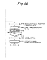
- step S36 If it is determined in step S36 that the set frequency has been returned to the initial frequency, that is, if the same PI station cannot be detected by the frequency sweeping process in the reception band, the processor reads out the original receiving frequency data held in step S21 (step S46).
- the frequency data which has been read out is supplied to the PLL circuit 7 (step S47) and the PLL timer is set (step S48). After the PLL timer has timed up (step S49), the audio muting is canceled (step S50).
- the frequency of the originally received station is set as a new receiving frequency (step S51). Thus, the received station has been returned to the originally received station.
- the PI data of the initially received station is previously held and in the case where the existence of a same network station cannot be detected by the network following function, if the existence of a received station whose reception signal level is equal to or higher than the set level and in which the reception PI data coincides with the holding PI data has been detected while executing a frequency sweeping operation, the frequency of such a receive d station is set as a new receiving frequency.
- a broadcasting station of the same program can be automatically searched, so that the possibility that a broadcasting station of the same program can be received can be improved.
Landscapes
- Engineering & Computer Science (AREA)
- Computer Hardware Design (AREA)
- Microelectronics & Electronic Packaging (AREA)
- Circuits Of Receivers In General (AREA)
Priority Applications (1)
| Application Number | Priority Date | Filing Date | Title |
|---|---|---|---|
| EP95201275A EP0669714B1 (de) | 1990-03-27 | 1991-03-27 | Verfahren zum Wählen einer Frequenz für einen RDS-Empfänger |
Applications Claiming Priority (4)
| Application Number | Priority Date | Filing Date | Title |
|---|---|---|---|
| JP78477/90 | 1990-03-27 | ||
| JP7847790A JPH03277022A (ja) | 1990-03-27 | 1990-03-27 | Rds受信機における受信周波数選択方法 |
| JP2085734A JP2731281B2 (ja) | 1990-03-30 | 1990-03-30 | Rds受信機における受信周波数選択方法 |
| JP85734/90 | 1990-03-30 |
Related Child Applications (2)
| Application Number | Title | Priority Date | Filing Date |
|---|---|---|---|
| EP95201275A Division EP0669714B1 (de) | 1990-03-27 | 1991-03-27 | Verfahren zum Wählen einer Frequenz für einen RDS-Empfänger |
| EP95201275.5 Division-Into | 1991-03-27 |
Publications (4)
| Publication Number | Publication Date |
|---|---|
| EP0451990A2 true EP0451990A2 (de) | 1991-10-16 |
| EP0451990A3 EP0451990A3 (en) | 1992-06-03 |
| EP0451990B1 EP0451990B1 (de) | 1996-06-19 |
| EP0451990B2 EP0451990B2 (de) | 2007-03-21 |
Family
ID=26419540
Family Applications (2)
| Application Number | Title | Priority Date | Filing Date |
|---|---|---|---|
| EP95201275A Expired - Lifetime EP0669714B1 (de) | 1990-03-27 | 1991-03-27 | Verfahren zum Wählen einer Frequenz für einen RDS-Empfänger |
| EP19910302686 Expired - Lifetime EP0451990B2 (de) | 1990-03-27 | 1991-03-27 | Verfahren zum Wählen einer Frequenz für einen RDS-Empfänger |
Family Applications Before (1)
| Application Number | Title | Priority Date | Filing Date |
|---|---|---|---|
| EP95201275A Expired - Lifetime EP0669714B1 (de) | 1990-03-27 | 1991-03-27 | Verfahren zum Wählen einer Frequenz für einen RDS-Empfänger |
Country Status (2)
| Country | Link |
|---|---|
| EP (2) | EP0669714B1 (de) |
| DE (2) | DE69120331T3 (de) |
Cited By (3)
| Publication number | Priority date | Publication date | Assignee | Title |
|---|---|---|---|---|
| EP0552442A3 (de) * | 1991-11-28 | 1995-03-22 | Kenwood Corp | |
| EP0701341A3 (de) * | 1994-09-07 | 1998-08-05 | Pioneer Electronic Corporation | Verfahren für die Senderauswahl in einem Sendernetz und Verwendung eines solchen Verfahrens in einem Radiodatenempfänger |
| EP0845860B1 (de) * | 1996-11-28 | 2002-02-27 | Nec Corporation | CDMA Kommunikationsendgerät mit Anfangsfrequenzerfassung |
Families Citing this family (1)
| Publication number | Priority date | Publication date | Assignee | Title |
|---|---|---|---|---|
| DE19638482A1 (de) * | 1996-09-20 | 1998-04-02 | Bosch Gmbh Robert | Verfahren zur Auswahl einer Sendefrequenz |
Family Cites Families (4)
| Publication number | Priority date | Publication date | Assignee | Title |
|---|---|---|---|---|
| DE2946755C2 (de) * | 1979-11-20 | 1984-08-09 | Philips Patentverwaltung Gmbh, 2000 Hamburg | Verfahren und Schaltungsanordnung für einen Rundfunkempfänger mit Sendersuchlauf |
| EP0584839B1 (de) * | 1986-12-19 | 1996-08-21 | Thomson Consumer Electronics Sales GmbH | Verfahren zum empfangsseitigen Auswerten zusätzlicher Informationen innerhalb eines Rundfunksignals |
| JPS6467037A (en) * | 1987-09-07 | 1989-03-13 | Clarion Co Ltd | Receiving method in rds system radio |
| JPH01151319A (ja) | 1987-12-08 | 1989-06-14 | Pioneer Electron Corp | Rds受信機における受信周波数選択方法 |
-
1991
- 1991-03-27 DE DE1991620331 patent/DE69120331T3/de not_active Expired - Lifetime
- 1991-03-27 DE DE1991633147 patent/DE69133147T2/de not_active Expired - Lifetime
- 1991-03-27 EP EP95201275A patent/EP0669714B1/de not_active Expired - Lifetime
- 1991-03-27 EP EP19910302686 patent/EP0451990B2/de not_active Expired - Lifetime
Cited By (3)
| Publication number | Priority date | Publication date | Assignee | Title |
|---|---|---|---|---|
| EP0552442A3 (de) * | 1991-11-28 | 1995-03-22 | Kenwood Corp | |
| EP0701341A3 (de) * | 1994-09-07 | 1998-08-05 | Pioneer Electronic Corporation | Verfahren für die Senderauswahl in einem Sendernetz und Verwendung eines solchen Verfahrens in einem Radiodatenempfänger |
| EP0845860B1 (de) * | 1996-11-28 | 2002-02-27 | Nec Corporation | CDMA Kommunikationsendgerät mit Anfangsfrequenzerfassung |
Also Published As
| Publication number | Publication date |
|---|---|
| EP0451990B2 (de) | 2007-03-21 |
| EP0451990B1 (de) | 1996-06-19 |
| DE69120331D1 (de) | 1996-07-25 |
| DE69120331T2 (de) | 1996-12-19 |
| DE69120331T3 (de) | 2007-11-22 |
| DE69133147T2 (de) | 2003-10-02 |
| EP0669714B1 (de) | 2002-11-13 |
| DE69133147D1 (de) | 2002-12-19 |
| EP0669714A3 (de) | 1995-09-27 |
| EP0451990A3 (en) | 1992-06-03 |
| EP0669714A2 (de) | 1995-08-30 |
Similar Documents
| Publication | Publication Date | Title |
|---|---|---|
| JP2571247B2 (ja) | ラジオデータ受信機における受信周波数選択方法 | |
| EP0451990B1 (de) | Verfahren zum Wählen einer Frequenz für einen RDS-Empfänger | |
| GB2240677A (en) | Automatic retuning in RDS receiver with means for reselecting original signal | |
| JP2788015B2 (ja) | Rds放送受信機 | |
| JPH02105731A (ja) | Rds受信機の制御方法 | |
| GB2247121A (en) | Rds radio with storage of transmitted other network information | |
| GB2240679A (en) | Method of selecting receiving frequency in RDS receiver | |
| JP2731281B2 (ja) | Rds受信機における受信周波数選択方法 | |
| JP2569347B2 (ja) | ラジオデータ受信機 | |
| JP2848896B2 (ja) | Rds受信機における受信方法 | |
| JP2688354B2 (ja) | Rds受信機 | |
| JP2848895B2 (ja) | Rds受信機における受信方法 | |
| JP2571270B2 (ja) | ラジオデータ受信機 | |
| JPH01160221A (ja) | Rds受信機における受信周波数選択方法 | |
| JP2688353B2 (ja) | ラジオデータによる制御機能を有する受信機 | |
| JP3763560B2 (ja) | 受信機 | |
| JP2562821B2 (ja) | ラジオデータ受信機 | |
| GB2208457A (en) | Radio data system protocol discrimination | |
| JP2948137B2 (ja) | 放送波多重データを利用したプリセットチャンネルメモリを有する受信機 | |
| JPH01160222A (ja) | Rds受信機における受信周波数選択方法 | |
| JP2965725B2 (ja) | Rds受信機の制御方法 | |
| JPH01202030A (ja) | Rds受信機の制御方法 | |
| JP2571249B2 (ja) | ラジオデータ受信機における受信周波数選択方法 | |
| JPH01177722A (ja) | ラジオデータ受信機における受信周波数選択方法 | |
| JP2583548B2 (ja) | ラジオデータ受信機 |
Legal Events
| Date | Code | Title | Description |
|---|---|---|---|
| PUAI | Public reference made under article 153(3) epc to a published international application that has entered the european phase |
Free format text: ORIGINAL CODE: 0009012 |
|
| AK | Designated contracting states |
Kind code of ref document: A2 Designated state(s): DE FR GB |
|
| PUAL | Search report despatched |
Free format text: ORIGINAL CODE: 0009013 |
|
| AK | Designated contracting states |
Kind code of ref document: A3 Designated state(s): DE FR GB |
|
| 17P | Request for examination filed |
Effective date: 19920908 |
|
| 17Q | First examination report despatched |
Effective date: 19950105 |
|
| GRAH | Despatch of communication of intention to grant a patent |
Free format text: ORIGINAL CODE: EPIDOS IGRA |
|
| GRAA | (expected) grant |
Free format text: ORIGINAL CODE: 0009210 |
|
| AK | Designated contracting states |
Kind code of ref document: B1 Designated state(s): DE FR GB |
|
| XX | Miscellaneous (additional remarks) |
Free format text: TEILANMELDUNG 95201275.5 EINGEREICHT AM 27/03/91. |
|
| REF | Corresponds to: |
Ref document number: 69120331 Country of ref document: DE Date of ref document: 19960725 |
|
| ET | Fr: translation filed | ||
| ET | Fr: translation filed | ||
| REG | Reference to a national code |
Ref country code: GB Ref legal event code: 746 Effective date: 19970205 |
|
| PLBI | Opposition filed |
Free format text: ORIGINAL CODE: 0009260 |
|
| 26 | Opposition filed |
Opponent name: INTERESSENGEMEINSCHAFT FUER RUNDFUNKSCHUTZRECHTE G Effective date: 19970319 Opponent name: ROBERT BOSCH GMBH Effective date: 19970318 |
|
| PLBF | Reply of patent proprietor to notice(s) of opposition |
Free format text: ORIGINAL CODE: EPIDOS OBSO |
|
| REG | Reference to a national code |
Ref country code: FR Ref legal event code: D6 |
|
| PLBF | Reply of patent proprietor to notice(s) of opposition |
Free format text: ORIGINAL CODE: EPIDOS OBSO |
|
| PLAW | Interlocutory decision in opposition |
Free format text: ORIGINAL CODE: EPIDOS IDOP |
|
| APAC | Appeal dossier modified |
Free format text: ORIGINAL CODE: EPIDOS NOAPO |
|
| APAE | Appeal reference modified |
Free format text: ORIGINAL CODE: EPIDOS REFNO |
|
| APAC | Appeal dossier modified |
Free format text: ORIGINAL CODE: EPIDOS NOAPO |
|
| APAC | Appeal dossier modified |
Free format text: ORIGINAL CODE: EPIDOS NOAPO |
|
| REG | Reference to a national code |
Ref country code: GB Ref legal event code: IF02 |
|
| PLAW | Interlocutory decision in opposition |
Free format text: ORIGINAL CODE: EPIDOS IDOP |
|
| APBP | Date of receipt of notice of appeal recorded |
Free format text: ORIGINAL CODE: EPIDOSNNOA2O |
|
| APBQ | Date of receipt of statement of grounds of appeal recorded |
Free format text: ORIGINAL CODE: EPIDOSNNOA3O |
|
| APAH | Appeal reference modified |
Free format text: ORIGINAL CODE: EPIDOSCREFNO |
|
| APBU | Appeal procedure closed |
Free format text: ORIGINAL CODE: EPIDOSNNOA9O |
|
| PUAH | Patent maintained in amended form |
Free format text: ORIGINAL CODE: 0009272 |
|
| STAA | Information on the status of an ep patent application or granted ep patent |
Free format text: STATUS: PATENT MAINTAINED AS AMENDED |
|
| 27A | Patent maintained in amended form |
Effective date: 20070321 |
|
| AK | Designated contracting states |
Kind code of ref document: B2 Designated state(s): DE FR GB |
|
| XX | Miscellaneous (additional remarks) |
Free format text: TEILANMELDUNG 95201275.5 EINGEREICHT AM 27/03/91. |
|
| ET3 | Fr: translation filed ** decision concerning opposition | ||
| PGFP | Annual fee paid to national office [announced via postgrant information from national office to epo] |
Ref country code: FR Payment date: 20100324 Year of fee payment: 20 |
|
| PGFP | Annual fee paid to national office [announced via postgrant information from national office to epo] |
Ref country code: GB Payment date: 20100322 Year of fee payment: 20 |
|
| PGFP | Annual fee paid to national office [announced via postgrant information from national office to epo] |
Ref country code: DE Payment date: 20100429 Year of fee payment: 20 |
|
| REG | Reference to a national code |
Ref country code: DE Ref legal event code: R071 Ref document number: 69120331 Country of ref document: DE |
|
| REG | Reference to a national code |
Ref country code: GB Ref legal event code: PE20 Expiry date: 20110326 |
|
| PG25 | Lapsed in a contracting state [announced via postgrant information from national office to epo] |
Ref country code: GB Free format text: LAPSE BECAUSE OF EXPIRATION OF PROTECTION Effective date: 20110326 |
|
| PG25 | Lapsed in a contracting state [announced via postgrant information from national office to epo] |
Ref country code: DE Free format text: LAPSE BECAUSE OF EXPIRATION OF PROTECTION Effective date: 20110327 |