EP0451569B1 - Beleuchtungseinrichtung für Fahrzeuge - Google Patents
Beleuchtungseinrichtung für Fahrzeuge Download PDFInfo
- Publication number
- EP0451569B1 EP0451569B1 EP91104415A EP91104415A EP0451569B1 EP 0451569 B1 EP0451569 B1 EP 0451569B1 EP 91104415 A EP91104415 A EP 91104415A EP 91104415 A EP91104415 A EP 91104415A EP 0451569 B1 EP0451569 B1 EP 0451569B1
- Authority
- EP
- European Patent Office
- Prior art keywords
- reflector
- lighting device
- frame
- bearing
- arm
- Prior art date
- Legal status (The legal status is an assumption and is not a legal conclusion. Google has not performed a legal analysis and makes no representation as to the accuracy of the status listed.)
- Expired - Lifetime
Links
- 230000001154 acute effect Effects 0.000 claims 1
- 238000010276 construction Methods 0.000 claims 1
- 230000000694 effects Effects 0.000 claims 1
- 230000000750 progressive effect Effects 0.000 claims 1
- 230000008719 thickening Effects 0.000 description 11
- 230000003287 optical effect Effects 0.000 description 9
- 238000011161 development Methods 0.000 description 3
- 230000018109 developmental process Effects 0.000 description 3
- 238000003780 insertion Methods 0.000 description 1
- 230000037431 insertion Effects 0.000 description 1
- 230000002093 peripheral effect Effects 0.000 description 1
Images
Classifications
-
- B—PERFORMING OPERATIONS; TRANSPORTING
- B60—VEHICLES IN GENERAL
- B60Q—ARRANGEMENT OF SIGNALLING OR LIGHTING DEVICES, THE MOUNTING OR SUPPORTING THEREOF OR CIRCUITS THEREFOR, FOR VEHICLES IN GENERAL
- B60Q1/00—Arrangement of optical signalling or lighting devices, the mounting or supporting thereof or circuits therefor
- B60Q1/02—Arrangement of optical signalling or lighting devices, the mounting or supporting thereof or circuits therefor the devices being primarily intended to illuminate the way ahead or to illuminate other areas of way or environments
- B60Q1/04—Arrangement of optical signalling or lighting devices, the mounting or supporting thereof or circuits therefor the devices being primarily intended to illuminate the way ahead or to illuminate other areas of way or environments the devices being headlights
- B60Q1/0408—Arrangement of optical signalling or lighting devices, the mounting or supporting thereof or circuits therefor the devices being primarily intended to illuminate the way ahead or to illuminate other areas of way or environments the devices being headlights built into the vehicle body, e.g. details concerning the mounting of the headlamps on the vehicle body
- B60Q1/0425—Arrangement of optical signalling or lighting devices, the mounting or supporting thereof or circuits therefor the devices being primarily intended to illuminate the way ahead or to illuminate other areas of way or environments the devices being headlights built into the vehicle body, e.g. details concerning the mounting of the headlamps on the vehicle body the housing being swivel mounted on the vehicle body
Definitions
- the invention relates to a lighting device for vehicles with the features according to the preamble of claim 1.
- Such a lighting device is known from DE-A-3 044 313.
- the first part is an optical unit consisting of reflector and lens
- the second part is a trough receiving the optical unit of a body part rigidly connected to the vehicle body.
- the bearing point of the optical unit consists of an opening made in a side wall of the trough, and the projection which engages in the opening is formed on the outside of the reflector.
- the resilient element also lies against the inside of the side wall of the trough and thus presses the optical unit against the bearing point.
- the optical unit is held in the trough by a resilient element inserted between it and the bottom surface of the trough, which presses the resilient element engaging in the opening against the inside of the opening.
- a resilient holding device of the optical unit it is not held in the trough without vibration.
- the vibrations can be so great that the latching connection between it and the body part carrying it is released.
- the optical unit and thus its light source will again assume exactly the same position. The latter is particularly important in the case of headlights for motor vehicles, since these would otherwise have to be readjusted, and is still for Headlights also a vibration-free attachment very important so that oncoming traffic is not dazzled.
- the object of the invention is to improve the lighting device described in the preamble in such a way that after one or more loosening and fastening of the first part, the light source is always precisely positioned to the second part and the first part can be connected to the second part as vibration-proof as possible and still both its assembly and disassembly can be carried out easily and quickly.
- This object is achieved by the features of the characterizing part of claim 1.
- the first part is clamped after pivoting toward the second part between the pivot bearing and a contact surface of the second part. The first part is released from this fixation when it is pivoted away from the second part after the detachable connection has been released.
- the result is a very simple and inexpensive solution.
- This solution is particularly expedient if the frame is mounted on the vehicle body at least adjustable about an axis and the lighting unit is a dimmed headlight.
- the reflector is both seen parallel to the pivot axis on the pivot bearing rattle-free and swivel easily and smoothly.
- the contact surfaces are formed by thickenings made in one piece with the reflector or the frame, for the demolding of which no adjustable tool parts are necessary.
- the reflector is seen in the frame in the region of the contact surfaces having a large distance from the pivot axis, rattling-free in the frame and is nevertheless easily pivotable out of the frame.
- the reflector is held particularly firmly between the pivot bearing and the contact surfaces of the frame.
- the reflector can be pivoted only with a small amount of force, since the curved contact surface lies linearly against the adjacent contact surface.
- an easy and quick threading of the bearing pins into the bearing shells is possible.
- the actuating lever holds the reflector against the possibility of pivoting out of the frame by the engagement of its locking lug in an undercut of the reflector.
- the reflector can be easily and quickly locked out Connection to be solved.
- Such an actuating lever can also be pivoted with a rod-shaped tool from the front of the headlamp if there is an opening to the side of the headlamp in the body.
- claims 21 to 27 when pivoting the actuating lever, the portion of the reflector which can be pivoted about the pivot axis is pressed out of the frame. This is particularly advantageous if there is a narrow gap between the lighting unit and the body wall surrounding it.
- Claim 28 specifies a development of the invention in which the reflector is connected to the vehicle body in a particularly fixed manner by the seal surrounding the lens.
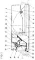
- Figure 1 is a plan view of a lighting unit, which consists of a frame rigidly connected to the vehicle and an optical unit inserted in the frame and
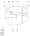
- Figure 2 shows the detail X of Figure 1.
- the lighting unit is a dimmed headlight for motor vehicles and is inserted into the opening of a body wall (1).
- the lighting unit consists of a first part, which consists of a bowl-shaped reflector made of plastic with an incandescent lamp (not shown) inserted in its opening and the lens (3) attached in the reflector (2), and a second part, which is made of Plastic-made frame (4) on which the reflector is detachably fastened with the lens and which is connected to the body wall (1) so as to be adjustable about a horizontal axis (not shown).
- the reflector (2) has a rectangular shape due to the upper and lower flats (5) Light exit opening and is inserted with its rear side in front into the frame (4), the opposite side walls (6) of which run approximately parallel and at a small distance from the flats (5) of the reflector (2).
- the reflector is mounted on the frame (6) so as to be adjustable about a pivot axis (7) running parallel to the short side.
- the pivot axis is formed in each case by a projection (8) molded onto the two flats (5), which is the bearing journal which engages in a bearing point (9) of the side walls (6) which serves as a bearing shell.
- the bearing shells (9) are introduced into the edge area of the side wall (6) facing the reflector and are opened approximately towards the center of the lens (3). Due to a thickening towards the reflector, the bearing journal (8) has the shoulder (10) with which it rests on the inside of the side walls (6).
- a rib-like thickened portion (11) running approximately in the swivel direction is attached to the flats (5) of the reflector (2). molded.
- the rib-like thickening (11) projects with its end section facing the rear of the headlamp into the frame (4) and overlaps with its end section with the free end section of the rib-like thickening (12) formed on the inside of the side walls (6).
- the rib-like thickening (11) lies with its contact surface (13) on the contact surface (14) of the rib-like thickening (12) facing the pivot axis (7).
- the contact surface (14) runs in a convex arc and the contact surface (13) in a straight line. For this reason, the contact surfaces (13 and 14) lie against one another in a line.
- the arch of the contact surface (14) extends to the free end of the rib-like thickening (12) and thus forms on free end of the thickening (12) the run-up slope (15) for the rib-like thickening (11).
- the rib-like thickening (11) has the run-up slope (16) which slides along the run-up slope (15) when the reflector is pivoted in and thereby presses the reflector (2) with its pin (8) into the bearing shell (9).
- the reflector is held by the releasable connection (17), which is formed by the actuating lever (18) pivotably mounted on the frame (4) and the undercut made in the wall (20) of the reflector, into which the locking lug ( 21) engages the actuating lever.
- the pivot axis (22) of the actuating lever (18) runs approximately parallel to the adjacent short edge region of the rectangular reflector (2) and is formed by a pin (23) molded onto a wall section of the frame (4).
- the coil spring (24) is placed on the bearing journal and rests with one free end on a wall section of the frame (4) and with the other end section on the first arm (25) of the actuating lever.
- the second arm (26) of the actuating lever is directed towards the lens (3) and has at its free end the latching lug (21) which is directed towards the reflector (2) and into an opening in the undercut (19) Wall (20) engages.
- the third arm (27) of the actuating lever extends approximately transversely to the direction of insertion of the reflector (2) and is directed towards it.
- the third arm (27) has on the side facing the reflector (2) the sliding surface (28) with which it slides along the end face of the wall (20) when the first arm (25) is pivoted and presses the section of the reflector (2) and the lens (3) which can be pivoted about the pivot axis (7) out of the frame (4) or the opening of the body wall (1).
- Pressing the reflector (2) out of the opening of the body wall (1) is imperative in this embodiment, since the seal (32) is glued to the peripheral edge area of the lens (3), which is pretensioned on the inside of the opening of the body wall (1) is present. After swiveling out the reflector, it can be pulled out with its bearing pin (8) from the open bearing shells (9) of the frame (4) in order, for. B. to change a light bulb.
- the actuating lever can engage in the undercut (19) of the reflector in a self-locking manner
- the actuating lever is held precisely by its resilient contact with the end face of the wall (29) of the frame (4), and its second arm (26) is pressed outwards by the pressure of the wall (20) on the locking lug (21) until the locking lug (21) engages in the undercut in a self-locking manner.
- the locking lug (21) rests under tension because the rubber-like, resilient element (30) glued to the rear of the reflector presses against the end face of the wall (29) of the frame (4). If the operating lever cannot be reached from the rear of the headlight, this can also be released from the front of the vehicle using a rod-shaped tool (31). However, it is necessary for the body wall to have a corresponding opening.
Landscapes
- Engineering & Computer Science (AREA)
- Mechanical Engineering (AREA)
- Lighting Device Outwards From Vehicle And Optical Signal (AREA)
- Non-Portable Lighting Devices Or Systems Thereof (AREA)
Applications Claiming Priority (2)
| Application Number | Priority Date | Filing Date | Title |
|---|---|---|---|
| DE4011703A DE4011703C1 (enExample) | 1990-04-11 | 1990-04-11 | |
| DE4011703 | 1990-04-11 |
Publications (2)
| Publication Number | Publication Date |
|---|---|
| EP0451569A1 EP0451569A1 (de) | 1991-10-16 |
| EP0451569B1 true EP0451569B1 (de) | 1994-06-22 |
Family
ID=6404202
Family Applications (1)
| Application Number | Title | Priority Date | Filing Date |
|---|---|---|---|
| EP91104415A Expired - Lifetime EP0451569B1 (de) | 1990-04-11 | 1991-03-21 | Beleuchtungseinrichtung für Fahrzeuge |
Country Status (3)
| Country | Link |
|---|---|
| EP (1) | EP0451569B1 (enExample) |
| AT (1) | ATE107584T1 (enExample) |
| DE (1) | DE4011703C1 (enExample) |
Families Citing this family (6)
| Publication number | Priority date | Publication date | Assignee | Title |
|---|---|---|---|---|
| DE4112794C1 (en) * | 1991-04-19 | 1992-09-10 | Hella Kg Hueck & Co, 4780 Lippstadt, De | Dipped headlamp arrangement for vehicle - has reflector and lamp disc pivoted relative to frame via locking lever |
| DE19533655C2 (de) * | 1995-09-12 | 1999-05-27 | Valeo Gmbh & Co Schliessyst Kg | Vorrichtung zur Befestigung von Bauteilen an Trägerteilen eines Kraftfahrzeuges |
| DE19544436B4 (de) * | 1995-11-29 | 2005-04-28 | Automotive Lighting Reutlingen | Fahrzeugscheinwerfer mit einem verschwenkbaren Reflektor |
| ITMI981565A1 (it) * | 1998-07-09 | 2000-01-09 | Magneti Marelli Spa | Sistema di accoppiamento di un corpo proiettore in particolare per un proiettore di un autoveicolo con una relativa calotta di |
| DE10000863C1 (de) * | 2000-01-12 | 2001-05-31 | Huf Huelsbeck & Fuerst Gmbh | Vorrichtung zur Befestigung eines Einsatzes in einer Öffnung eines Trägers bei Fahrzeugen, insbesondere eines Türgriffs in der Öffnung einer Tür-Außenverkleidung |
| DE10260785B4 (de) * | 2002-12-23 | 2005-04-21 | Daimlerchrysler Ag | Nutzfahrzeug, insbesondere Lastkraftwagen |
Family Cites Families (4)
| Publication number | Priority date | Publication date | Assignee | Title |
|---|---|---|---|---|
| DE3030427A1 (de) * | 1980-08-12 | 1982-03-25 | Bosch Gmbh Robert | Beleuchtungseinrichtung fuer kraftfahrzeuge |
| DE3402274A1 (de) * | 1984-01-24 | 1985-08-01 | Bosch Gmbh Robert | Scheinwerfer fuer fahrzeuge, insbesondere fuer kraftfahrzeuge |
| DE3516711A1 (de) * | 1985-05-09 | 1986-11-13 | Bosch Gmbh Robert | Scheinwerfer-blinkleuchten-einheit fuer personenkraftfahrzeuge |
| DE3525198A1 (de) * | 1985-07-15 | 1987-01-15 | Opel Adam Ag | Leuchteneinheit |
-
1990
- 1990-04-11 DE DE4011703A patent/DE4011703C1/de not_active Expired - Lifetime
-
1991
- 1991-03-21 AT AT91104415T patent/ATE107584T1/de active
- 1991-03-21 EP EP91104415A patent/EP0451569B1/de not_active Expired - Lifetime
Also Published As
| Publication number | Publication date |
|---|---|
| EP0451569A1 (de) | 1991-10-16 |
| DE4011703C1 (enExample) | 1991-10-02 |
| ATE107584T1 (de) | 1994-07-15 |
Similar Documents
| Publication | Publication Date | Title |
|---|---|---|
| DE69709446T2 (de) | Vorrichtung zur Kontrolle der Neigung eines Scheinwerfers | |
| DE69738243T2 (de) | Fahrzeugscheinwerfer- Einstelleinrichtung des Reflektors | |
| DE4311419C2 (de) | Befestigungsvorrichtung für einen Schweinwerfer | |
| DE4407108C2 (de) | Fahrzeugscheinwerfer mit einer verstellbaren Blendenanordnung | |
| DE2847908A1 (de) | Blinkleuchte-scheinwerfer-befestigung in kraftfahrzeugkarosserien | |
| EP0451569B1 (de) | Beleuchtungseinrichtung für Fahrzeuge | |
| EP0381851B1 (de) | Abgeblendeter Kraftfahrzeugscheinwerfer nach dem Projektionsprinzip | |
| DE3913151C1 (enExample) | ||
| EP0429922B1 (de) | Scheinwerfer nach dem Projektionsprinzip | |
| EP0208923A2 (de) | Leuchteneinheit | |
| DE3218184C2 (de) | Innenleuchte für Fahrzeuge | |
| EP0590454B1 (de) | Scheinwerfer für Fahrzeuge | |
| DE69605063T2 (de) | Scheinwerfer | |
| DE3729984C1 (de) | Kraftfahrzeugscheinwerfer | |
| EP0268759A2 (de) | Scheinwerfer für Fahrzeuge nach dem Projektionsprinzip | |
| DE4112794C1 (en) | Dipped headlamp arrangement for vehicle - has reflector and lamp disc pivoted relative to frame via locking lever | |
| EP0058312A1 (de) | Fahrzeugscheinwerfer | |
| DE4407006C1 (de) | Lichteinheit für Fahrzeuge | |
| DE19742816A1 (de) | Befestigungssystem für eine Blinkleuchte | |
| DE10022235B4 (de) | Schaltvorrichtung für eine Blendenanordnung | |
| DE2914959C2 (de) | Zusatzscheinwerfer für Kraftfahrzeuge | |
| EP0084073B1 (de) | Halterahmen für eine Leuchte und Verbindungselement | |
| EP0972984A2 (de) | Fahrzeugscheinwerfer | |
| DE60129490T2 (de) | Kfz-Scheinwerfer mit Maske und Korrektur | |
| DE3302651C2 (enExample) |
Legal Events
| Date | Code | Title | Description |
|---|---|---|---|
| PUAI | Public reference made under article 153(3) epc to a published international application that has entered the european phase |
Free format text: ORIGINAL CODE: 0009012 |
|
| AK | Designated contracting states |
Kind code of ref document: A1 Designated state(s): AT FR GB IT |
|
| 17P | Request for examination filed |
Effective date: 19920407 |
|
| 17Q | First examination report despatched |
Effective date: 19931109 |
|
| GRAA | (expected) grant |
Free format text: ORIGINAL CODE: 0009210 |
|
| AK | Designated contracting states |
Kind code of ref document: B1 Designated state(s): AT FR GB IT |
|
| REF | Corresponds to: |
Ref document number: 107584 Country of ref document: AT Date of ref document: 19940715 Kind code of ref document: T |
|
| ITF | It: translation for a ep patent filed | ||
| GBT | Gb: translation of ep patent filed (gb section 77(6)(a)/1977) |
Effective date: 19940805 |
|
| ET | Fr: translation filed | ||
| PLBE | No opposition filed within time limit |
Free format text: ORIGINAL CODE: 0009261 |
|
| STAA | Information on the status of an ep patent application or granted ep patent |
Free format text: STATUS: NO OPPOSITION FILED WITHIN TIME LIMIT |
|
| 26N | No opposition filed | ||
| PGFP | Annual fee paid to national office [announced via postgrant information from national office to epo] |
Ref country code: AT Payment date: 19990324 Year of fee payment: 9 |
|
| PGFP | Annual fee paid to national office [announced via postgrant information from national office to epo] |
Ref country code: FR Payment date: 20000316 Year of fee payment: 10 |
|
| PG25 | Lapsed in a contracting state [announced via postgrant information from national office to epo] |
Ref country code: AT Free format text: LAPSE BECAUSE OF NON-PAYMENT OF DUE FEES Effective date: 20000321 |
|
| PGFP | Annual fee paid to national office [announced via postgrant information from national office to epo] |
Ref country code: GB Payment date: 20010226 Year of fee payment: 11 |
|
| PG25 | Lapsed in a contracting state [announced via postgrant information from national office to epo] |
Ref country code: FR Free format text: LAPSE BECAUSE OF NON-PAYMENT OF DUE FEES Effective date: 20011130 |
|
| REG | Reference to a national code |
Ref country code: FR Ref legal event code: ST |
|
| REG | Reference to a national code |
Ref country code: GB Ref legal event code: IF02 |
|
| PG25 | Lapsed in a contracting state [announced via postgrant information from national office to epo] |
Ref country code: GB Free format text: LAPSE BECAUSE OF NON-PAYMENT OF DUE FEES Effective date: 20020321 |
|
| GBPC | Gb: european patent ceased through non-payment of renewal fee |
Effective date: 20020321 |
|
| PG25 | Lapsed in a contracting state [announced via postgrant information from national office to epo] |
Ref country code: IT Free format text: LAPSE BECAUSE OF NON-PAYMENT OF DUE FEES;WARNING: LAPSES OF ITALIAN PATENTS WITH EFFECTIVE DATE BEFORE 2007 MAY HAVE OCCURRED AT ANY TIME BEFORE 2007. THE CORRECT EFFECTIVE DATE MAY BE DIFFERENT FROM THE ONE RECORDED. Effective date: 20050321 |