EP0451346B1 - Plate treating apparatus using a caterpillar - Google Patents
Plate treating apparatus using a caterpillar Download PDFInfo
- Publication number
- EP0451346B1 EP0451346B1 EP19900123216 EP90123216A EP0451346B1 EP 0451346 B1 EP0451346 B1 EP 0451346B1 EP 19900123216 EP19900123216 EP 19900123216 EP 90123216 A EP90123216 A EP 90123216A EP 0451346 B1 EP0451346 B1 EP 0451346B1
- Authority
- EP
- European Patent Office
- Prior art keywords
- endless belt
- plate
- heat transfer
- transfer medium
- rotary shaft
- Prior art date
- Legal status (The legal status is an assumption and is not a legal conclusion. Google has not performed a legal analysis and makes no representation as to the accuracy of the status listed.)
- Expired - Lifetime
Links
Images


Classifications
-
- F—MECHANICAL ENGINEERING; LIGHTING; HEATING; WEAPONS; BLASTING
- F26—DRYING
- F26B—DRYING SOLID MATERIALS OR OBJECTS BY REMOVING LIQUID THEREFROM
- F26B15/00—Machines or apparatus for drying objects with progressive movement; Machines or apparatus with progressive movement for drying batches of material in compact form
- F26B15/10—Machines or apparatus for drying objects with progressive movement; Machines or apparatus with progressive movement for drying batches of material in compact form with movement in a path composed of one or more straight lines, e.g. compound, the movement being in alternate horizontal and vertical directions
- F26B15/12—Machines or apparatus for drying objects with progressive movement; Machines or apparatus with progressive movement for drying batches of material in compact form with movement in a path composed of one or more straight lines, e.g. compound, the movement being in alternate horizontal and vertical directions the lines being all horizontal or slightly inclined
- F26B15/18—Machines or apparatus for drying objects with progressive movement; Machines or apparatus with progressive movement for drying batches of material in compact form with movement in a path composed of one or more straight lines, e.g. compound, the movement being in alternate horizontal and vertical directions the lines being all horizontal or slightly inclined the objects or batches of materials being carried by endless belts
-
- B—PERFORMING OPERATIONS; TRANSPORTING
- B27—WORKING OR PRESERVING WOOD OR SIMILAR MATERIAL; NAILING OR STAPLING MACHINES IN GENERAL
- B27D—WORKING VENEER OR PLYWOOD
- B27D3/00—Veneer presses; Press plates; Plywood presses
- B27D3/04—Veneer presses; Press plates; Plywood presses with endless arrangement of moving press plates, belts, or the like
-
- B—PERFORMING OPERATIONS; TRANSPORTING
- B27—WORKING OR PRESERVING WOOD OR SIMILAR MATERIAL; NAILING OR STAPLING MACHINES IN GENERAL
- B27N—MANUFACTURE BY DRY PROCESSES OF ARTICLES, WITH OR WITHOUT ORGANIC BINDING AGENTS, MADE FROM PARTICLES OR FIBRES CONSISTING OF WOOD OR OTHER LIGNOCELLULOSIC OR LIKE ORGANIC MATERIAL
- B27N3/00—Manufacture of substantially flat articles, e.g. boards, from particles or fibres
- B27N3/08—Moulding or pressing
- B27N3/24—Moulding or pressing characterised by using continuously acting presses having endless belts or chains moved within the compression zone
-
- B—PERFORMING OPERATIONS; TRANSPORTING
- B30—PRESSES
- B30B—PRESSES IN GENERAL
- B30B15/00—Details of, or accessories for, presses; Auxiliary measures in connection with pressing
- B30B15/34—Heating or cooling presses or parts thereof
-
- B—PERFORMING OPERATIONS; TRANSPORTING
- B30—PRESSES
- B30B—PRESSES IN GENERAL
- B30B5/00—Presses characterised by the use of pressing means other than those mentioned in the preceding groups
- B30B5/04—Presses characterised by the use of pressing means other than those mentioned in the preceding groups wherein the pressing means is in the form of an endless band
- B30B5/06—Presses characterised by the use of pressing means other than those mentioned in the preceding groups wherein the pressing means is in the form of an endless band co-operating with another endless band
-
- F—MECHANICAL ENGINEERING; LIGHTING; HEATING; WEAPONS; BLASTING
- F25—REFRIGERATION OR COOLING; COMBINED HEATING AND REFRIGERATION SYSTEMS; HEAT PUMP SYSTEMS; MANUFACTURE OR STORAGE OF ICE; LIQUEFACTION SOLIDIFICATION OF GASES
- F25D—REFRIGERATORS; COLD ROOMS; ICE-BOXES; COOLING OR FREEZING APPARATUS NOT OTHERWISE PROVIDED FOR
- F25D13/00—Stationary devices, e.g. cold-rooms
- F25D13/06—Stationary devices, e.g. cold-rooms with conveyors carrying articles to be cooled through the cooling space
- F25D13/062—Stationary devices, e.g. cold-rooms with conveyors carrying articles to be cooled through the cooling space with refrigerated conveyors
-
- F—MECHANICAL ENGINEERING; LIGHTING; HEATING; WEAPONS; BLASTING
- F26—DRYING
- F26B—DRYING SOLID MATERIALS OR OBJECTS BY REMOVING LIQUID THEREFROM
- F26B23/00—Heating arrangements
- F26B23/10—Heating arrangements using tubes or passages containing heated fluids, e.g. acting as radiative elements; Closed-loop systems
-
- F—MECHANICAL ENGINEERING; LIGHTING; HEATING; WEAPONS; BLASTING
- F26—DRYING
- F26B—DRYING SOLID MATERIALS OR OBJECTS BY REMOVING LIQUID THEREFROM
- F26B3/00—Drying solid materials or objects by processes involving the application of heat
- F26B3/18—Drying solid materials or objects by processes involving the application of heat by conduction, i.e. the heat is conveyed from the heat source, e.g. gas flame, to the materials or objects to be dried by direct contact
- F26B3/20—Drying solid materials or objects by processes involving the application of heat by conduction, i.e. the heat is conveyed from the heat source, e.g. gas flame, to the materials or objects to be dried by direct contact the heat source being a heated surface, e.g. a moving belt or conveyor
Definitions
- the present invention relates to a plate treating apparatus according to the pre-characterizing part of claim 1, 3 and claim 4, respectively.
- An apparatus of this type is known from DE-C-256 293 or DE-C-257 672.
- a dryer circulating hot air transversely or longitudinally of the veneer; a multiplaten press having hot plates vertically or laterally arranged, the hot plates being supplied with a heating medium such as steam, hot oil and warm water; a single platen press having hot plates disposed in a single layer; a continuous press having a steel belt, a mesh belt or a metallic sheet wound around each hot plate in an endless shape; a continuous press having endless chains extended around recesses formed in a pair in an outer surface of a hot plate; and a slat conveyor type press using narrow hot plates.
- a dryer circulating hot air transversely or longitudinally of the veneer
- a multiplaten press having hot plates vertically or laterally arranged, the hot plates being supplied with a heating medium such as steam, hot oil and warm water
- a single platen press having hot plates disposed in a single layer
- a continuous press having a steel belt, a mesh belt or a metallic sheet wound around each hot plate in an endless shape
- a continuous press having endless
- Dryers are widely used for drying veneers. It is well known that in terms of heat efficiency, a single stage press and a multistage press, which bring hot plates into direct contact with a veneer, are superior to an indirect heating dryer circulating hot air over surfaces of veneer.
- Such presses are disadvantageous in that mechanisms to convey a veneer to and away from the hot plates are rather complicated, and in that the veneer is liable to be damaged in moving to and away from the hot plates.
- a veneer is placed on an endless steel belt or a pair of chain conveyor and is turned around to move to a position above a hot plate. After heat dried, the veneer is carried away by turning the steel belt or the chain conveyors. In this manner, automatic carrying in and out of the veneer is achieved.
- a belt like member such as a steel belt
- the hot plate makes an indirect heat contact with a veneer for heating, resulting in a low heat efficiency.
- such a heating operation can cause the belt like member to be damaged with the lapse of time.
- an elevating mechanism is needed.
- the elevating mechanism is actuated to elevate the chain conveyors or a hot plate every time when a veneer is placed on or taken away from the chain conveyors, and when the veneer is brought into contact with the surface of the hot plate. This is because the veneer is turned over while transported by the conveyors.
- slat conveyor type press a group of slats are heated, and hence burners, heaters and like devices are arranged at predetermined positions near the caterpillar for indirect heating of a veneer.
- DE-C-256 293 discloses an apparatus according to the pre-characterizing part of claim 1 in which a rotary shaft means provided between the supporting shafts is surrounded by a chamber having circular cross section.
- the connecting tubes extend in a radial direction from the rotary shaft means and connect said chamber with a plurality of hot plates.
- DE-C-257 672 discloses a similar arrangement wherein said chamber surrounding the rotary shaft means is subdivided into a supply chamber and a discharge chamber, wherein both the supply chamber and the discharge chamber is connected to a respective hose disposed substantially parallel with respect to the endless belt of hot plates. Each hot plate is connected with said hose via a short duct.
- the connection between said endless hoses and the supply chamber and the discharge chamber, respectively, is achieved by means of flexible hoses.
- the problem underlying the present invention is to provide an apparatus in which the heat transfer medium supplying passage and the heat transfer medium discharge passage can easily be connected to the hot plates.
- the rotary shaft means When the endless belt is actuated, the rotary shaft means is synchronously rotated so that the rotary shaft means makes one revolution for one turn of the endless belt.
- the heat transfer medium is supplied from the heat transfer medium supply portion of the rotary shaft means to the heat transfer medium passage of each hot plate for heating or cooling the hot plate.
- the heat transfer medium After heat exchange is accomplished, the heat transfer medium is returned from the outlet of the heat transfer medium passage to the heat transfer medium discharge portion of the rotary shaft means.
- the heat transfer medium is always circulated through each hot plate of the endless belt which is being turned, and hence the heat transfer medium circulating method and the plate treating apparatus according to the present invention are capable of directly heating or cooling hot plates without any outer heat source.
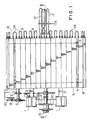
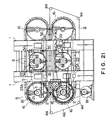
- FIGS. 1 to 3 illustrate a plate treating apparatus according to the present invention.
- a plate to be heat dried or cooled (hereinafter referred to as plate to be treated) is placed on the plate treating apparatus and is heat treated while being transported.
- a pair of vertical frames 1 and 1 are erected on a floor on one side of a caterpillar 9 of the plate treating apparatus, and a pair of parallel beams 2 and 2 are provided to the vertical frames 1 and 1 in the same horizontal plane to laterally extend.
- a pair of lateral supporting shafts 3 and 3 are supported on bearings (not shown) which are arranged on beams 2 and 2 in a conveying direction of the caterpillar 9.
- the caterpillar 9 is constructed as follows.
- a pair of sprocket wheels 4 and 4 are mounted on opposite ends of each of the supporting shafts 3 and 3, and a pair of endless chains 5 and 5 extend between sprocket wheels 4 located at respective sides of the caterpillar 9 to form a pair of chain conveyors 6 and 6.
- a multiplicity of parallel strip-shaped hot plates 8 are closely arranged in an endless manner on the chain conveyors 6 and 6 through attachments 7 secured to outer faces of the chains 5.
- Each of the hot plates 8 is provided in it with a heat transfer medium passage through which a heating medium or a coolant (both hereinafter referred to as heat transfer medium) passes.
- the heat transfer medium passage may be formed in a single row or in rows.
- a rotary shaft 12 is rotatably supported by bearings on portions of beams 2 and 2, the portions being surrounded by hot plates 8 of the caterpillar 9.
- the rotary shaft 12 is provided at its one end with a header 12A.
- the interior of the header 12A is separated into a heat transfer medium supplying portion 10 and a heat transfer medium discharging portion 11.
- the other end of the rotary shaft 12 near the vertical frames 1 and 1 has a rotary joint 15 fitted around it.
- the rotary joint 15 is provided with a supply port 13 and a discharging port 14.
- Connecting tubes 17 are provided to connect between the heat transfer medium supplying portion 10 and an inlet of the heat transfer medium passage of each hot plate 8 and between the heat transfer medium discharging portion 11 and an outlet of the heat transfer medium passage of each hot plate 8.
- the connecting tubes 17 have such a length that they reach turning portions 16 of the caterpillar 9.
- the number of the connecting tubes 17 is the same as the number of the hot plates 8 of the caterpillar 9. In the embodiment of FIGS. 1 to 3, the number of hot plates 8 is 32 and hence that of the connecting tubes 17 is 32.
- reference numeral 17A designates a connecting pipe binder through which connecting tubes 17 pass for preventing them from being caught in each other.
- the caterpillar 9 is, as shown in FIG. 2, rotated by transmitting a driving force of an electric motor 19 to a sprocket wheel 18, mounted around one end of the shaft 3, through a speed reducer 20 and chain 23A.
- a sprocket wheel 21 which has teeth different in number from the teeth of the sprocket wheel 18 is mounted around the shaft 3.
- the sprocket wheel 21 is connected to a sprocket wheel 22 on the rotary shaft 12 through a chain 23B in such a manner that one turn of the caterpillar 9 is synchronized with one turn of the rotary shaft 12.
- an electrical synchronizing device in which pulse generators are connected to the shaft 3 of the caterpillar 9 and the rotary shaft 12 for electrical synchronization.
- the caterpillar 9 is horizontally arranged, it may be installed in an inclined manner or in a vertical manner.
- Supplying of the heat transfer medium to and discharging of it from hot plates 8 are not individually made but made in groups of adjacent hot plates 8.
- the inlet of the heat transfer medium passage of a leading hot plate 8 is connected to one end of a U-shaped connecting tube 17.
- the one end of each connecting tube 17 is extendable to the turning portions 16.
- the outlet of a hot plate 8 and the inlet of an adjacent hot plate 8 of the same group are communicated through a U-shaped connecting joint 24 as shown in FIG. 1.
- the outlet of the heat transfer medium passage of a trailing hot plate 8 of the group is communicated to the heat transfer medium discharging portion 11 of the rotary shaft 12 through another connecting tube 17.
- With such a heat transfer medium circulating unit only two connecting tubes 17 are used in each of the heat transfer medium supplying portion 10 and heat transfer medium discharging portion 11, and the diameter of the rotary shaft 12 and particularly the diameter of the portion connecting the connecting tube 17 is reduced.
- the caterpillar 9 and the rotary shaft 12 are synchronously controlled so that the rotary shaft 12 makes one revolution for one turn of the caterpillar 9.
- the rotary shaft 12 has a circular cross section and hence the peripheral speed and the angular speed thereof are constant.
- the caterpillar 9 forms a track-shaped locus as it turns, and hence the angular speed thereof is not constant although the peripheral speed is constant.
- the length of the connecting tubes 17 must be variable due to the difference in locus between the caterpillar 9 and the rotary shaft 12.
- the connecting tubes 17 may use an extendable mechanism, for example, a telescopic cylinder, which can extend from the rotary shaft 12 to the turning portions 16.
- the connecting tubes 17 may be connected through rotary joints between the hot plates 8 and the rotary shaft 12.
- Flexible pipes are preferably used for the connecting tubes 17 to vary their length and to prevent twisting.
- connecting tubes 17 When flexible tubes are used as the connecting tubes 17, their flexible portions gradually extend as hot plates 8 to which they are connected moves from positions nearest to the rotary shaft 12 to turning portions 16 of the caterpillar, and then the flexible tubes gradually bend. Although torsion is applied to each flexible tube as its one end passes through each turning portion 16, the flexibility of the pipe is capable of overcoming the torsion.
- Gaps between adjacent hot plates 8 and 8 become slightly wider at each of the turning portion 16 and 16 than at the other positions.
- Each of the U-shaped connecting joints 24 which circulate a heat transfer medium through a group of hot plates 8 makes the distance between its legs larger at the turning portions 16.
- a heat transfer medium is always supplied to and discharged from the rotary shaft 12 through the rotary joint 15.
- a heat transfer medium such as steam or hot oil, passes through the rotary shaft 12 to dry the veneer.
- a coolant is always transported through the rotary shaft 12 for maintaining the hot plates 8 at a predetermined temperature when the temperature of a dried veneer is to drop to a temperature, at which an adhesive is not cured, for applying the adhesive, or when a resin laminated veneer is to be cooled after hot pressed.
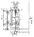
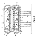
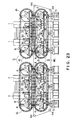
- FIGS. 4 to 8 illustrate an embodiment in which a pair of caterpillars 9 of the preceding embodiment are arranged one above the other in an opposing manner.
- a plate 25 to be treated is conveyed between the caterpillars 9 and 9 in a sandwiched manner for heating or cooling treatment.
- the opposite surfaces of the plate 25 to be treated are subjected to a thermal treatment and hence efficiency of the thermal treatment is fairly increased.
- a sprocket wheel 27 which is mounted around the shaft 3 is connected to a sprocket wheel 26 through a chain 28, the sprocket wheel 26 being engaged with the chain 23A which interconnects the speed reducer 20 to the sprocket wheel 18 of the lower caterpillar 9 to transmit rotation.
- the upper and lower caterpillars 9 and 9 are turned at the same speed but in opposite directions.
- the driving system of the rotary shaft 12 of the upper caterpillar 9 includes a sprocket wheel 30 which is connected to a sprocket wheel 29 through a chain 31.
- the sprocket wheel 29 engages the chain 23B of the lower caterpillar 9.
- This driving system transmits to the rotary shaft 12 of the upper caterpillar 9 rotation with the same speed as and in the opposite direction to the rotation of the rotary shaft 12 of the lower caterpillar 9.
- the beams 2 and 2 which support the upper and lower caterpillar 9 and its accompanying parts in a cantilever fashion, are capable of changing their vertical positions by a suitable devices (not shown) such as screw mechanisms, hydraulic jacks and a like mechanism.
- a plate 25 to be treated such as a veneer
- the plate treating apparatus is capable of drying the plate 25 to be treated.
- a depressing conveyor including parallel conveyor belts 32 may be, as shown in FIG. 9, arranged above the lower caterpillar 9 in a parallel manner.
- a plate 25 to be treated, placed on hot plates 8 of the caterpillar 9 is moved by turning the caterpillar 9. During this movement, the plate 25 to be treated is subjected at its lower surface to a direct thermal influence from hot plates 8 which are maintained at a predetermined temperature.
- the upper surface of the plate 25 to be treated is slightly depressed by synchronously turning the depressing conveyor 32 in a direction opposite to the turning direction of the caterpillar 9, so that the depressing conveyor 32 depresses the plate 25 to be treated not to separate from the hot plates. This prevents cracks from being produced in a direction of fibers due to contraction.
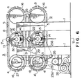
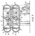
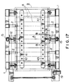
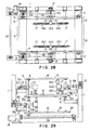
- FIGS. 10 to 13 illustrate two embodiments in which opposite ends of the supporting shafts 3 and 3 of the sprocket wheels are supported.
- a pair of vertical frames 1 and 1 are erected with transverse spacing.
- Two pairs of beams 2 and 2 are provided to each frame 1 in a vertically spaced manner to extend horizontally for supporting corresponding sprocket wheels 4.
- the rotary shaft 12 of the right side of the lower caterpillar 9 is omitted for illustration purpose.
- each of the caterpillars 9 and 9 of the embodiment of FIGS. 10 and 11 a pair of opposed rotary shafts 12 and 12 are used.
- Each of the rotary shafts 12 is solely for supplying or discharging a heat transfer medium.
- two rotary shafts 12 are provided to only one side frame 1 to supply and discharge a heat transfer medium.
- connecting tubes 17 are connected to the inner surfaces of the hot plates 8 and are placed within the caterpillars 9 and 9.
- FIGS. 14 and 15 there is illustrated another embodiment, in which hot plates 8 of a pair of caterpillars 9 and 9 are brought into intimate contact to a plate 25 to be treated to improve the efficiency of the thermal processing.
- a pressing mechanism 33 is provided to a beam 2 of one of the caterpillars 9 and 9 (the upper caterpillar 9 in this embodiment).
- the pressing mechanism 33 enhances the bonding thereof.
- the pressing mechanism 33 includes a pair of fluid cylinders 34 and 34 mounted to the beam 2 in a direction perpendicular to the adjacent hot plates 8.
- a piston rod 35 of each fluid cylinder 34 is fastened at its lower end to one of two pressing bars 36 and 36 (only one of which is shown) through a joint member not shown.
- the pressing bars 36 and 36 extend in the conveying direction of the plate 25 to be treated.
- Two pairs of pendants 37 and 37 are provided to depend from the beam 2 of the upper caterpillar 9. Each pair of pendants 37 and 37 slidably pass through the corresponding pressing bar 36. A locking nut 38 is threaded to the lower end of each pendant 37 to adjust the limit of depressing link portions of the chain 5 to which hot plates 8 are attached.
- fluid cylinders 34 instead of fluid cylinders 34, conventional crank mechanisms, screw mechanisms or springs may be used.
- each pair of supporting members 39 and 39 are supported on the beam 2 in a threaded manner for adjustment of vertical positions thereof although two pairs of supporting members 39 and 39 are shown in FIG. 16.
- Two pairs of supporting members 39 and 39 are arranged right below the pressing bars 36 and 36, respectively, and the other one pair is located at a center position of the lower caterpillar 9.
- Each pair of supporting members 39 and 39 are connected at their upper ends to a supporting bar 40 which is in contact with a link portion of the chain 5 of the lower caterpillar 9.
- the supporting members 39 and 39 serve to bear reaction forces of the upper caterpillar 9 through the supporting bars 40.
- the lower limit of the hot plates which constitute caterpillars 9 and 9 is determined by turning the locking nuts 38 threaded around pendants 37 according to the thickness of the plate 25 to be treated.
- the caterpillars 9 and 9 of FIGS. 14 and 15 are supported on frame 1 in a cantilever fashion.
- a reaction force bearing mechanism may be provided for bearing the upper and lower caterpillars 9 and 9, and is preferably arranged at the sides of the caterpillars 9 and 9 remote from the frame 1.
- a reaction force bearing mechanism a strut, using trains of rollers, or a conveyor including a wide endless belt may be provided in such a manner that the upper traveling surface thereof makes a contact with the lower traveling plane of the lower caterpillar 9.
- supporting members including discs 51 may be, as illustrated in FIG. 16, arranged to bear the lower traveling plane of lower caterpillar 9, each disc being supported on a pair of rails 50.
- the discs 51 are located at least at positions just below supporting shafts 3 of the caterpillars 9 and may be also arranged on the side of frame 1 to totally bear vertical reaction forces.
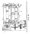
- FIG. 17 illustrates another embodiment in which a pair of headers 41 and 41 are provided to supply and discharge a heat transfer medium.
- the headers 41 and 41 are made of a resilient material such as rubber and are capable of bending at the turning portions 16 and 16 of a caterpillar 9 as the caterpillar 9 turns. More specifically, each of the hot plates 8 is provided at its inner surface with an inlet 42 and outlet 43 of the heat transfer medium passage.
- the headers 41 and 41 are disposed in parallel with each other along the traveling direction of each caterpillar 9. One of the headers 41 and 41 serves to supply a heat transfer medium and the other to discharge the heat transfer medium.
- Each of the headers 41 and 41 is longitudinally provided at its outer surface with supply ports or discharge ports which are connected to corresponding inlets 42 or outlets 43 of hot plates 8 through joints (not shown). Both the number of the joints to connect the inlets 42 of hot plates 8 to the supply ports of the one header 41 and the number of the joints to connect outlets 43 to the discharge ports are 32 when the number of the hot plates 8 is 32.
- Rotary joints 15 and 15 which supply and discharge the heat transfer medium are arranged in the vicinity of respective vertical frames 1 and 1 opposingly erected.
- a rotary shaft 12 is rotatably supported at its proximal end to each of the rotary joints 15 and 15 and is connected at its distal end to the corresponding header 41 through a conventional joint such as a flange.
- the flexible headers 41 and 41 is capable of deforming in the shape of the track of the caterpillar 9, and hence they follow the turning of the caterpillar 9 with a gap equal to the length of the joints which interconnect the caterpillar 9 and the headers 41. Also in this embodiment, the headers 41 and 41 are expanded at the turning portions of the caterpillar 9 as gaps between adjacent hot plates 8 become larger.
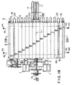
- FIGS. 18 to 22 show an embodiment in which plates 25 to be treated are smoothly carried in and out of plate treating apparatus above described.
- a pair of V-shaped or U-shaped grooves 45 and 45 are, as shown in FIG. 20, formed in an outer surface of each hot plate 8 with a longitudinal interval and in parallel with the conveying direction.
- Two sets of four pulleys 44, 44, 44 and 44 are arranged close to the veneer-carrying-in position and carrying-out position of the lower caterpillar 9, the two sets being disposed in a transversely spaced manner.
- An endless guiding belt 46 such as a wire, a piano wire and a chain, extends around each set of the pulleys 44, 44, 44 and 44 and fits into a corresponding groove 45.
- the caterpillars 9 are arranged so that corresponding grooves 45 of end-to-end facing caterpillars 9 of adjacent plate treating apparatuses are aligned.
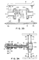
- Several sets of pulleys 44, 44, 44 and 44 are arranged in the vicinity of the plate-carrying-in and -out positions of the combined plate treating apparatuses as shown in FIG. 23, and a guiding belt 46 extends around each set of pulleys 44, 44, 44 and 44 to fit in corresponding grooves 45 of the plate treating apparatuses.
- This embodiment facilitates the carrying in and out of the plate 25 to be treated and transfer of the plate 25 between two plate treating apparatuses.
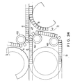
- FIG. 24 Another embodiment in which plate treating apparatuses are arranged in series without guide belts 46 above described is illustrated in FIG. 24.
- the hot plates 8 of this embodiment are made smaller in width than those of the preceding embodiments.
- a lower caterpillar 9 of one of adjacent plate treating apparatuses is arranged to project at its one end, for example, a trailing end from one end (trailing end) of the upper caterpillar 9 of the same plate treating apparatus.
- an upper sprocket wheel 4A of the trailing end of the lower caterpillar 9 of the left-hand plate treating apparatus is projected from the trailing end of the upper caterpillar 9 of the same plate treating apparatus.
- a leading end of an upper caterpillar 9 of an adjacent or right hand plate treating apparatus is located to project from the leading end of the lower caterpillar 9 of the same plate treating apparatus.
- a lower sprocket wheel 4B of the leading end of the upper caterpillar 9 is located to project from the leading end of the lower caterpillar 9.
- the plate treating apparatuses are arranged in such a manner that the projected leading end of the upper caterpillar 9 of the left-hand plate treating apparatus overlaps the projected trailing end of the lower caterpillar of the right-hand plate treating apparatus.
- a guide plate member 47 is provided between the projected end of the lower caterpillar 9 of the left-hand plate treating apparatus and the retreated end of the lower caterpillar 9 of the right-hand plate treating apparatus for guiding a plate to be treated.
- FIG. 25 illustrates another embodiment in which a heat transfer medium circulating system is provided outside the caterpillars 9 and 9.
- Sprocket wheels 4 of the caterpillars 9 and 9 are rotatably supported on beams 2 and 2 horizontally projected from one of two vertical frames 1 and 1.
- the other frame 1 rotatably supports horizontal rotary shafts 12 and 12 of which heat transfer medium supplying portions 10 and heat transfer medium discharging portions 11 are connected to connecting tubes 17.
- the connecting tubes 17 are connected to hot plates 8 of the caterpillars 9 and 9.
- the caterpillars 9 and 9 and the rotary shafts 12 and 12 are synchronously turned to swing connecting tubes 17 like jumping ropes to supply and discharge the heat transfer medium.
- the heat transfer medium supplying and discharging header 12A of each rotary shaft 12 is capable of reciprocating between a projection limit X and retreat limit Y by fluid cylinders 48 or like members in such a manner that the heat transfer medium supplying portion 10 and heat transfer medium discharging portion 11 make one reciprocating movement for one turn of the corresponding caterpillar to keep the connecting tubes 17 from being excessively slackened.
- FIGS. 28 to 34 illustrate embodiments which enhances the capacity of connecting tubes 17 to follow the shape of the caterpillars 9 and 9.
- the connecting tubes 17 connect hot plates 8 of the caterpillars 9 and 9 and rotary shafts 12.
- FIGS. 28 and 29 two pairs of sprocket wheels 4 and 4 of each caterpillar 9 are supported on respective vertical frames 1 and 1 erected along opposite sides of the caterpillars 9 and 9.
- the supporting structure of the caterpillars 9 and 9 and their related structure are the same as those of FIGS. 10 to 13, and hence corresponding parts are designated by like reference numerals and descriptions thereof are omitted.
- a flexible member 150 is attached at its opposite ends to each connecting tube 17 in the vicinity of respective ends for protecting the connecting tube 17.
- the flexible member 150 is deformable according to the curvature of the turning portions 16 and 16. The resiliency and flexibility of the flexible members 150 enables that one revolution of the rotary shafts 12 is synchronized with one turn of respective caterpillars 9.
- Cable bears 151 which are bendable in the shape of jointed limbs as shown in FIG. 30 or steel belts 152 as in FIG. 31 are suitably used as the flexible members 150.
- Both connecting tubes 17 and flexible members 150 are resilient and hence bend to follow the curvature of the inner circumference of the caterpillar 9 every time when they reach the turning portions 16.
- binding members such as a wire 153 at an appropriate interval for positively preventing separation.
- connection of the header 12A of the rotary shaft 12 and hot plates 8 through connecting tubes 17 as shown in FIGS. 30 to 33 is effective for turning the rotary shaft 12 together with the caterpillar 9.
- a sprocket wheel 54 is mounted around one of the supporting shafts 3 and 3 of each pair and is rotated by an electric motor 19 through a speed reducer 55 and a chain (not shown).
- Each caterpillar 9 is provided with a hollow inside, and hence this embodiment adopts a caterpillar driving system in which supporting shafts 3 and 3 of each pair are independently rotated. The other supporting shaft 3 of the same pair is rotated synchronously with the one supporting shaft 3 by the motor 19 through the speed reducer 55 and a chain transmission including a synchronizing shaft 56.
- the synchronizing shaft 56 transversely extends below the lower caterpillar 9.
- the rotary shaft 12 When each of the caterpillars 9 and 9 is turned, the rotary shaft 12 can be synchronously rotated only by the pulling force of the connecting tubes 17 as shown in FIG. 32 since the connecting tubes 17 have rigidity to some extent.
- a sprocket wheel 57 having teeth different in number from the teeth of the sprocket wheel 54 may be mounted around the same shaft 3, and the sprocket wheel 57 may be connected to a sprocket wheel 58 mounted on the rotary shaft 12 through a chain 59.
- the rotary shaft 12 is synchronously controlled in a mechanical manner to make a revolution for a turn of the caterpillar 9.
- an electrical synchronizing control may be adopted in which pulse generators are provided to shafts 3 and rotary shafts 12 of each caterpillar 9.
- each caterpillar 9 of the embodiments includes two groups of adjacent hot plates 8, each group containing 16 hot plates 8.
- An inlet 8a of a leading hot plate 8 of each group is connected to a heat transfer medium supplying portion 10 of the rotary shaft 12 through a connecting tube 17 which extends along the inner faces of the hat plates 8 in a plane perpendicular to the rotary shaft 12.
- each of the hot plates 8 is provided in its inner surface with an inlet 8a and an outlet 8b.
- the inlet 8a of one of the hot plates 8 is connected to the outlet 8b of the adjacent hot plate 8 of the same group through a connecting joint 24.
- each hot plate 8 is provided at its opposite ends with an inlet 8a and an outlet 8b, and the inlet 8a of one end of a hot plate 8 is connected to the outlet 8b of one end of the adjacent hot plate 8 of the same group.
- the outlet 8b of a hot plate 8, from which the heat transfer medium of the group of the hot plates 8 are discharged, is connected to a discharging part of the rotary shaft 12 through another connecting tube 17, which extends perpendicularly to the rotary shaft 12 and partly along the inner surfaces of some hot plates 8.
- FIG. 34 illustrate a heat transfer medium circulating system for a caterpillar 9 which is supported on a frame in a cantilever fashion.
- a pipe 60 is inserted into a hollow rotary shaft 12 and is communicated at one end to a supplying chamber 12B of a header 12A and at the other end to a rotary joint 15.
- a discharging passage 61 is defined between the rotary shaft 12 and the pipe 60.
- the discharging passage 61 is communicated at one end to a discharging chamber 12C of the header 12A and the other end thereof is closed with a sealing member 62.
- An outer shell member 63 surrounds the other end of the rotary shaft 12 to define a discharging chamber 64.
- the discharging passage 61 communicates to the discharging chamber 64 through a communication hole 65 formed through the rotary shaft 12.
- the discharging chamber 64 is connected to a drain or a recirculating system through a conduit 66.
- connecting tubes 17 are connected to the header 12A perpendicularly to the axis of the rotary shaft 12. This arrangement produces little torsional stress in the connecting tubes 17 and provides excellent synchronization of the rotary shaft 12 with the caterpillar 9. Thus, it is possible to make the circumferential length of the caterpillar 9 fairly long.
- the rotary shaft 12 is rotated by the pulling force of the connecting tubes 17 plus the physical synchronization control.
- FIG. 35 shows a guide device 70 disposed between two adjoining caterpillars for assuring smooth transfer of plates to be treated from one caterpillar to the succeeding caterpillar.
- the device 70 comprises a guide member 71 pivotally supported by a horizontal pivot 72 which is disposed at a position higher than the supporting shafts of the sprocket wheels 4.
- the guide member 71 has a concave surface 73 having a curvature equivalent to the curvature of the turning portion 16.
- At the upper and lower ends of the concave surface 73 there are provided horizontally extending protrusions 74a and 74b.
- the device 70 further comprises a stationary structure 75 having an upper surface 76 and an upwardly sloping bridging plate 77.
- Upper and lower compression coil springs 78 and 79 may be interposed between the stationary structure 75 and the guide member 71.
- the hot plates 8 are in mutually adjoining relation without clearances therebetween. However, in the region of the turning portion 16 open gaps are formed between adjoining hot plates 8, as shown, so that without any measures the spring biased upper protrusion 74a would plunge into the gaps.
- the dimensional relations of the two protrusions and the hot plates on the caterpillar are determined such that during the period in which the upper protrusion 74a is closely facing the surface of any one of the hot plates 8, the lower protrusion 74b is also closely facing the surface of one of the hot plates 8 and that during the period in which the upper protrusion 74a is facing the gaps between adjoining hot plates 8, the lower protrusion 74b is facing the gaps between adjoining hot plates 8 and caused to plunge into the gaps due to the force of the lower spring 79 whereby the upper protrusion 74a is positively prevented from engaging the gaps.
- the upper protrusion 74a slidingly engage the surfaces of the hot plates 8 while it is facing the surfaces, thereby to serve for peeling the plates being treated off the surfaces of the hot plates at the moment each plate is entering the region of the turning portion 16, and that the upper protrusion 74a is prevented from plunging into the gaps between adjoining hot plates 8, to positively avoid interference between the protrusion 74a and the hot plates 8.
- the thus peeled plates are conveyed onto the succeeding caterpillar via the plates 76 and 77.
- FIGS. 36 and 37 indicate a modified form in which the caterpillar includes timing belts 80 instead of the endless chains used in the foregoing embodiments.
- the timing belts 80 have teeth 81 that engage teeth 82 of pulleys 4A used in place of the sprocket wheels 4.
- To the outer surface of the timing belt 80 is secured a flexible endless plate 83 of a heat resisting material.
- the plate 83 may be formed integrally with the timing belts 80.
- Hot plates 8 are secured to the outer surface of the plate 83 by means of bolts 84. Alternatively, the hot plates 8 may be secured to the endless plate 83 through engagement of protrusions 85 and recesses of a dovetail-shaped cross section, as shown in FIG. 38.
- the embodiment shown in FIG. 37 has two spaced apart timing belts 80.
- the space between the two timing belts 80 can be advantageously used for connecting the connecting tubes 17 for the heat transfer medium to the hot plates 8.
- the use of the timing belts 80 is advantageous in that the pitch of the teeth 81 of the belts 80 need not have a relation to the dimension of the hot plates 8, whereas in the case of the endless chain, the dimension of the hot plates 8 in the longitudinal direction of the chains must be determined on the basis of the pitch of the endless chain.
- the heat transfer medium use may be made of steam, hot oil, warm water or a like medium for heating a plate to be treated.
- a cooling gas, cold water, or a like medium may be according to the present invention used as the cooling medium.
- various kinds of plate like materials such as a veneer, chip board, fiber board, resin laminated board, plywood and a like material may be heat dried, hot pressed, or cooled.
Landscapes
- Engineering & Computer Science (AREA)
- Mechanical Engineering (AREA)
- Life Sciences & Earth Sciences (AREA)
- General Engineering & Computer Science (AREA)
- Forests & Forestry (AREA)
- Wood Science & Technology (AREA)
- Chemical & Material Sciences (AREA)
- Combustion & Propulsion (AREA)
- Microbiology (AREA)
- Physics & Mathematics (AREA)
- Thermal Sciences (AREA)
- Manufacturing & Machinery (AREA)
- Sustainable Development (AREA)
- Drying Of Solid Materials (AREA)
Applications Claiming Priority (2)
| Application Number | Priority Date | Filing Date | Title |
|---|---|---|---|
| JP82088/90 | 1990-03-29 | ||
| JP8208890A JPH0387201A (ja) | 1989-03-30 | 1990-03-29 | 無限軌道への熱媒体給排方法およびその無限軌道を用いた板体処理装置 |
Publications (3)
| Publication Number | Publication Date |
|---|---|
| EP0451346A2 EP0451346A2 (en) | 1991-10-16 |
| EP0451346A3 EP0451346A3 (en) | 1992-11-25 |
| EP0451346B1 true EP0451346B1 (en) | 1995-07-05 |
Family
ID=13764693
Family Applications (1)
| Application Number | Title | Priority Date | Filing Date |
|---|---|---|---|
| EP19900123216 Expired - Lifetime EP0451346B1 (en) | 1990-03-29 | 1990-12-04 | Plate treating apparatus using a caterpillar |
Country Status (3)
| Country | Link |
|---|---|
| EP (1) | EP0451346B1 (fi) |
| DE (1) | DE69020720T2 (fi) |
| FI (1) | FI96447C (fi) |
Families Citing this family (10)
| Publication number | Priority date | Publication date | Assignee | Title |
|---|---|---|---|---|
| EP0589113A1 (fr) * | 1992-09-22 | 1994-03-30 | Charpente Menuiserie Chasseneuillaise C.M.C. | Dispositif de transfert de pièces de bois dans un four de séchage par micro-ondes |
| IT233508Y1 (it) * | 1994-06-17 | 2000-01-28 | Cremona Lorenzo | Dispositivo di essicazione a guida perfezionata per sfogliati di legno |
| DE19710209A1 (de) * | 1997-03-12 | 1998-09-17 | Meyer Herbert Gmbh Co Kg | Vorrichtung zum Verkleben flächiger Materialien |
| ATE290676T1 (de) * | 1999-08-31 | 2005-03-15 | Skaginn Hf | Wärmebehandlungskammer und verfahren zur wärmebehandlung von produkten |
| US7841462B2 (en) | 2006-05-24 | 2010-11-30 | Span Tech, Llc | Side-flexing conveyor chain with pivoting slats and related methods |
| CN108180739B (zh) * | 2018-02-12 | 2023-08-15 | 郭永广 | 一种适用于乳胶垫烘干处理装置 |
| CN111806045A (zh) * | 2020-07-03 | 2020-10-23 | 重庆中航新型材料科技有限公司 | 用于生产复合节能板的专用设备 |
| CN113059647B (zh) * | 2021-03-11 | 2023-12-19 | 众拓新材料(菏泽)有限公司 | 一种环保刨花板压制设备 |
| CN113071117B (zh) * | 2021-03-31 | 2023-01-10 | 重庆伟星新型建材有限公司 | 管道热处理设备 |
| CN216465272U (zh) * | 2021-05-19 | 2022-05-10 | 东莞市星文新型建材有限公司 | 一种应用于柔性沙砖烘干成型的自动化设备 |
Family Cites Families (6)
| Publication number | Priority date | Publication date | Assignee | Title |
|---|---|---|---|---|
| DE256293C (fi) * | ||||
| DE257672C (fi) * | ||||
| US2071999A (en) * | 1934-03-17 | 1937-02-23 | Laucks I F Inc | Continuous press for production of board-like products |
| US2365804A (en) * | 1940-05-14 | 1944-12-26 | John W Clerke | Continuous press |
| DE803759C (de) * | 1948-10-02 | 1951-04-09 | Ernst Teschner Dipl Ing | Kuehl- oder heizbares Foerderband |
| FR2412395A1 (fr) * | 1977-12-22 | 1979-07-20 | Martin Jean Marie | Machine pour le sechage et le jointage de placages en continu et par contact |
-
1990
- 1990-11-26 FI FI905826A patent/FI96447C/fi active IP Right Grant
- 1990-12-04 EP EP19900123216 patent/EP0451346B1/en not_active Expired - Lifetime
- 1990-12-04 DE DE1990620720 patent/DE69020720T2/de not_active Expired - Lifetime
Also Published As
| Publication number | Publication date |
|---|---|
| EP0451346A2 (en) | 1991-10-16 |
| FI905826A0 (fi) | 1990-11-26 |
| DE69020720T2 (de) | 1996-03-14 |
| FI96447C (fi) | 1996-06-25 |
| FI96447B (fi) | 1996-03-15 |
| EP0451346A3 (en) | 1992-11-25 |
| DE69020720D1 (de) | 1995-08-10 |
| FI905826A (fi) | 1991-09-30 |
Similar Documents
| Publication | Publication Date | Title |
|---|---|---|
| EP0451346B1 (en) | Plate treating apparatus using a caterpillar | |
| CA1308257C (en) | Method of and apparatus for bending and tempering glass sheets | |
| EP1007346B1 (en) | Method and apparatus for processing corrugated paperboard | |
| FI92385C (fi) | Uuni ja menetelmä lasilevyjen kuumentamiseksi | |
| FI72669C (fi) | Kontinuerligt driven maskin foer torkning och sammanfogning av faner. | |
| WO1986005441A1 (en) | Hot press for treating a web of material | |
| US5121683A (en) | Method and apparatus for a continuously working heating-plate press | |
| FI82921C (fi) | Foerfarande och anordning foer boejning och haerdning av glasskiva. | |
| WO1998047699B1 (en) | Method and apparatus for processing corrugated paperboard | |
| US5014772A (en) | Method of circulating a heat transfer medium through a caterpillar and a plate treating apparatus using the caterpillar | |
| EP0750986B1 (en) | Web holddown mechanism for corrugator double backer | |
| US5213819A (en) | Continuously operating press | |
| US3418727A (en) | Veneer dryer | |
| EP0352241A1 (en) | Heat exchange belt conveying apparatus, in particular for thin sheet products and the like | |
| JP3165512B2 (ja) | 無限軌道を構成する熱板 | |
| JP2954362B2 (ja) | 無限軌道を用いた板体処理装置 | |
| KR20100107628A (ko) | 열간 프레스 성형용 가열로의 이송장치 | |
| JPH0387201A (ja) | 無限軌道への熱媒体給排方法およびその無限軌道を用いた板体処理装置 | |
| CN1082180C (zh) | 用于旋转切制的薄木片的具有改进导向装置的烘干装置 | |
| FI62972B (fi) | Press foer utoevning av ytpressning pao ett laengdavsnitt av en framloepande materialbana | |
| CA2322418C (en) | Process and double-belt press for the continuous production of board materials | |
| US6684527B1 (en) | Veneer dryer and method of drying | |
| JP2962764B2 (ja) | 無限軌道を用いた板体処理装置 | |
| CN218203486U (zh) | 一种多层拉幅定型机 | |
| US6074520A (en) | Heated holddown mat for corrugator double backer |
Legal Events
| Date | Code | Title | Description |
|---|---|---|---|
| PUAI | Public reference made under article 153(3) epc to a published international application that has entered the european phase |
Free format text: ORIGINAL CODE: 0009012 |
|
| AK | Designated contracting states |
Kind code of ref document: A2 Designated state(s): DE FR IT |
|
| PUAL | Search report despatched |
Free format text: ORIGINAL CODE: 0009013 |
|
| AK | Designated contracting states |
Kind code of ref document: A3 Designated state(s): DE FR IT |
|
| 17P | Request for examination filed |
Effective date: 19930415 |
|
| 17Q | First examination report despatched |
Effective date: 19931008 |
|
| GRAA | (expected) grant |
Free format text: ORIGINAL CODE: 0009210 |
|
| AK | Designated contracting states |
Kind code of ref document: B1 Designated state(s): DE FR IT |
|
| REF | Corresponds to: |
Ref document number: 69020720 Country of ref document: DE Date of ref document: 19950810 |
|
| ET | Fr: translation filed | ||
| ITF | It: translation for a ep patent filed |
Owner name: MODIANO & ASSOCIATI S.R.L. |
|
| PLBE | No opposition filed within time limit |
Free format text: ORIGINAL CODE: 0009261 |
|
| STAA | Information on the status of an ep patent application or granted ep patent |
Free format text: STATUS: NO OPPOSITION FILED WITHIN TIME LIMIT |
|
| 26N | No opposition filed | ||
| PGFP | Annual fee paid to national office [announced via postgrant information from national office to epo] |
Ref country code: FR Payment date: 20091202 Year of fee payment: 20 |
|
| PGFP | Annual fee paid to national office [announced via postgrant information from national office to epo] |
Ref country code: IT Payment date: 20091229 Year of fee payment: 20 |
|
| PGFP | Annual fee paid to national office [announced via postgrant information from national office to epo] |
Ref country code: DE Payment date: 20100226 Year of fee payment: 20 |
|
| PG25 | Lapsed in a contracting state [announced via postgrant information from national office to epo] |
Ref country code: DE Free format text: LAPSE BECAUSE OF EXPIRATION OF PROTECTION Effective date: 20101204 |