EP0450482A2 - Dispositif avec un poste de chauffage et un poste de formation - Google Patents
Dispositif avec un poste de chauffage et un poste de formation Download PDFInfo
- Publication number
- EP0450482A2 EP0450482A2 EP91104849A EP91104849A EP0450482A2 EP 0450482 A2 EP0450482 A2 EP 0450482A2 EP 91104849 A EP91104849 A EP 91104849A EP 91104849 A EP91104849 A EP 91104849A EP 0450482 A2 EP0450482 A2 EP 0450482A2
- Authority
- EP
- European Patent Office
- Prior art keywords
- heating
- workpiece
- station
- heating device
- needle
- Prior art date
- Legal status (The legal status is an assumption and is not a legal conclusion. Google has not performed a legal analysis and makes no representation as to the accuracy of the status listed.)
- Withdrawn
Links
Images


Classifications
-
- B—PERFORMING OPERATIONS; TRANSPORTING
- B29—WORKING OF PLASTICS; WORKING OF SUBSTANCES IN A PLASTIC STATE IN GENERAL
- B29C—SHAPING OR JOINING OF PLASTICS; SHAPING OF MATERIAL IN A PLASTIC STATE, NOT OTHERWISE PROVIDED FOR; AFTER-TREATMENT OF THE SHAPED PRODUCTS, e.g. REPAIRING
- B29C51/00—Shaping by thermoforming, i.e. shaping sheets or sheet like preforms after heating, e.g. shaping sheets in matched moulds or by deep-drawing; Apparatus therefor
-
- B—PERFORMING OPERATIONS; TRANSPORTING
- B29—WORKING OF PLASTICS; WORKING OF SUBSTANCES IN A PLASTIC STATE IN GENERAL
- B29B—PREPARATION OR PRETREATMENT OF THE MATERIAL TO BE SHAPED; MAKING GRANULES OR PREFORMS; RECOVERY OF PLASTICS OR OTHER CONSTITUENTS OF WASTE MATERIAL CONTAINING PLASTICS
- B29B13/00—Conditioning or physical treatment of the material to be shaped
- B29B13/02—Conditioning or physical treatment of the material to be shaped by heating
- B29B13/023—Half-products, e.g. films, plates
-
- B—PERFORMING OPERATIONS; TRANSPORTING
- B29—WORKING OF PLASTICS; WORKING OF SUBSTANCES IN A PLASTIC STATE IN GENERAL
- B29C—SHAPING OR JOINING OF PLASTICS; SHAPING OF MATERIAL IN A PLASTIC STATE, NOT OTHERWISE PROVIDED FOR; AFTER-TREATMENT OF THE SHAPED PRODUCTS, e.g. REPAIRING
- B29C51/00—Shaping by thermoforming, i.e. shaping sheets or sheet like preforms after heating, e.g. shaping sheets in matched moulds or by deep-drawing; Apparatus therefor
- B29C51/26—Component parts, details or accessories; Auxiliary operations
- B29C51/261—Handling means, e.g. transfer means, feeding means
-
- B—PERFORMING OPERATIONS; TRANSPORTING
- B29—WORKING OF PLASTICS; WORKING OF SUBSTANCES IN A PLASTIC STATE IN GENERAL
- B29C—SHAPING OR JOINING OF PLASTICS; SHAPING OF MATERIAL IN A PLASTIC STATE, NOT OTHERWISE PROVIDED FOR; AFTER-TREATMENT OF THE SHAPED PRODUCTS, e.g. REPAIRING
- B29C51/00—Shaping by thermoforming, i.e. shaping sheets or sheet like preforms after heating, e.g. shaping sheets in matched moulds or by deep-drawing; Apparatus therefor
- B29C51/26—Component parts, details or accessories; Auxiliary operations
- B29C51/42—Heating or cooling
- B29C51/421—Heating or cooling of preforms, specially adapted for thermoforming
- B29C51/424—Heating or cooling of preforms, specially adapted for thermoforming using a heated fluid
-
- B—PERFORMING OPERATIONS; TRANSPORTING
- B29—WORKING OF PLASTICS; WORKING OF SUBSTANCES IN A PLASTIC STATE IN GENERAL
- B29C—SHAPING OR JOINING OF PLASTICS; SHAPING OF MATERIAL IN A PLASTIC STATE, NOT OTHERWISE PROVIDED FOR; AFTER-TREATMENT OF THE SHAPED PRODUCTS, e.g. REPAIRING
- B29C51/00—Shaping by thermoforming, i.e. shaping sheets or sheet like preforms after heating, e.g. shaping sheets in matched moulds or by deep-drawing; Apparatus therefor
- B29C51/26—Component parts, details or accessories; Auxiliary operations
- B29C51/42—Heating or cooling
- B29C51/421—Heating or cooling of preforms, specially adapted for thermoforming
- B29C51/425—Heating or cooling of preforms, specially adapted for thermoforming using movable heating devices
-
- B—PERFORMING OPERATIONS; TRANSPORTING
- B29—WORKING OF PLASTICS; WORKING OF SUBSTANCES IN A PLASTIC STATE IN GENERAL
- B29C—SHAPING OR JOINING OF PLASTICS; SHAPING OF MATERIAL IN A PLASTIC STATE, NOT OTHERWISE PROVIDED FOR; AFTER-TREATMENT OF THE SHAPED PRODUCTS, e.g. REPAIRING
- B29C35/00—Heating, cooling or curing, e.g. crosslinking or vulcanising; Apparatus therefor
- B29C35/02—Heating or curing, e.g. crosslinking or vulcanizing during moulding, e.g. in a mould
- B29C2035/0211—Heating or curing, e.g. crosslinking or vulcanizing during moulding, e.g. in a mould resistance heating
-
- B—PERFORMING OPERATIONS; TRANSPORTING
- B29—WORKING OF PLASTICS; WORKING OF SUBSTANCES IN A PLASTIC STATE IN GENERAL
- B29C—SHAPING OR JOINING OF PLASTICS; SHAPING OF MATERIAL IN A PLASTIC STATE, NOT OTHERWISE PROVIDED FOR; AFTER-TREATMENT OF THE SHAPED PRODUCTS, e.g. REPAIRING
- B29C33/00—Moulds or cores; Details thereof or accessories therefor
- B29C33/02—Moulds or cores; Details thereof or accessories therefor with incorporated heating or cooling means
- B29C33/04—Moulds or cores; Details thereof or accessories therefor with incorporated heating or cooling means using liquids, gas or steam
-
- B—PERFORMING OPERATIONS; TRANSPORTING
- B29—WORKING OF PLASTICS; WORKING OF SUBSTANCES IN A PLASTIC STATE IN GENERAL
- B29C—SHAPING OR JOINING OF PLASTICS; SHAPING OF MATERIAL IN A PLASTIC STATE, NOT OTHERWISE PROVIDED FOR; AFTER-TREATMENT OF THE SHAPED PRODUCTS, e.g. REPAIRING
- B29C51/00—Shaping by thermoforming, i.e. shaping sheets or sheet like preforms after heating, e.g. shaping sheets in matched moulds or by deep-drawing; Apparatus therefor
- B29C51/08—Deep drawing or matched-mould forming, i.e. using mechanical means only
- B29C51/082—Deep drawing or matched-mould forming, i.e. using mechanical means only by shaping between complementary mould parts
Definitions
- the invention relates to a device with a heating station and a molding station for producing a molded part from a flat, three-dimensionally deformable workpiece, which consists of thermoplastic or contains such plastic.
- thermoplastic materials such as, for example, automotive interior trim parts and the like are known in large numbers and work in a more or less satisfactory manner. Disadvantages in most cases are that there is too much waste, that the temperature is too high, which creates toxic fumes, that the energy consumption is relatively large, and that the devices have to be specially designed for certain molded parts and are difficult to convert, etc.
- the invention is therefore based on the object of providing a device for producing thin-walled molded parts which consist of thermoplastic plastics or at least contain thermoplastic plastics, this device having improvements over the above-mentioned disadvantages compared to known devices of the type mentioned.
- the invention provides that at least one heating device is arranged in the heating station and that at least one heating device can simultaneously be moved as a carrier for the workpiece into the molding station.
- the use of a heating device which can be moved or moved from the heating station into the forming station allows the workpiece to be heated in the least possible way, since it no longer cools down during transport to the forming station, but is kept at its optimal temperature. While the thin and mostly large-area workpiece previously lost a considerable amount of heat when it was transferred from the heating station to the forming station, this is no longer the case when using a heating device which can be moved from the heating station to the forming station. As a result, lower temperatures, to which the workpiece must be heated, lower energy consumption and, finally, a lower release of harmful vapors and gases that escape from the heated, thermoplastic containing workpiece.
- a lower heating device and an upper heating device are preferably located in the heating station, between which the flat workpiece is arranged for heating.
- the upper heating device also serves as a movable support for the workpiece to be deformed, in particular if a lower mold is arranged in the forming station, on which the flat workpiece can be placed.
- At least one of the two heating devices works with at least two media, namely with electric current for heating and with hot air for heating an open-pore or air-permeable workpiece.
- a heating device is in fact able to heat both homogeneous workpieces and air-permeable workpieces, it also being useful if at least one of the two heating devices additionally has a cooling device, for example in the form of water channels.
- a cooling device for example in the form of water channels.
- the thin-walled workpiece consist of different materials, such as a homogeneous thermoplastic with a melting temperature of X-degree Celcius and an open-cell thermoplastic with a melting temperature of Y-Degree Celcius when using the heating devices according to the invention, it is possible to expose such a workpiece on its two sides to different temperatures and different types of heat.
- grippers which can optionally be used are also provided, which grip the heated workpiece in the molding station with needles and hold it at least before the molding process.
- These needle grippers require a maximum of 30 to 40 mm of material on the edge of each workpiece in order to be able to grip the respective workpiece. This means that you can work with blanks that are already tightly tolerated and the resulting waste is extremely low.
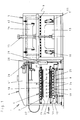
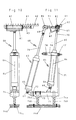
- a device 1 for producing a molded part 2 from a flat, three-dimensionally deformable, single-layer or multi-layer workpiece 3, which consists of or contains thermoplastic plastic comprises a heating station 4 and a molding station 5 according to FIG. 1.
- the heating station 4 contains at least one a heating device 6 or two cooperating heating devices 6 and 7, which heat the workpiece 3 between them, are arranged there according to the exemplary embodiment shown in the figures.
- the lower heating device 7 is e.g. 1 in the form of a spindle drive from a lower position according to FIG. 1 into an upper position according to FIG. 2, so that the workpiece 3 resting or deposited there on the lower heating device 7 can be moved as close as possible to the upper heating device 6 or in direct contact arrives with the upper heater 6.
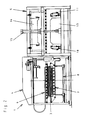
- the upper heating device 6 is not only used for heating workpieces 3, but it can also be moved from the heating station 4 into the forming station 5 or moved there on rollers 9 and thus serves at the same time as a carrier and transport device for transporting the heated workpiece 3 from the heating station 4 into the forming station 5.
- the heating device 6 furthermore has suitable holding means for the workpiece 3 hanging under it according to the exemplary embodiment. These holding means can e.g. work with suction air.
- the heating device 6 transports the workpiece 3 from the heating station 4 into the forming station 5 according to FIG. 3 has, the workpiece 3 is taken over there by one or more gripping devices 10, 11 and held in a clamped state. This is indicated with the aid of arrows a in FIG. 3, which show the direction of pull of the gripping devices 10, 11.
- a perforated conveyor belt 12 which is used for automatic loading of the heating station in the direction of arrow b (FIG 1 and 3) is provided.
- a perforated conveyor belt 12 is e.g. a teflon tape.
- Suitable molding parts are located in the molding station 5. According to the exemplary embodiment shown in FIGS. 1-6, these are a lower mold 13 and an upper mold 14.
- the gripping devices 10 and 11 hold the workpiece 3 between the lower mold 13 and the upper mold 14 after being taken over by the heating device 6, and as soon as the When the heating device 6 serving the carrier and the transporter has left the molding station 5 again, the lower mold 13 and the upper mold 14 move together for the purpose of deforming the workpiece 3 and producing the desired three-dimensionally deformed molded part 2.
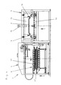
- FIG. 4 shows this working step, the lower mold 13 being moved upwards against the upper mold 14 located there according to the exemplary embodiment.
- the lifting device 15 for the lower mold 13 is e.g. a piston-cylinder device is provided. It is also ensured that the gripping devices 10, 11 release the workpiece 3 in good time when the deformation process between the lower mold 13 and upper mold 14 begins.
- the lower mold 13 and the upper mold 14 are separated again or, according to the exemplary embodiment, the lower mold 13 moves back into its lower starting position according to FIG. 5.
- the molded part 2 is still suspended under the upper mold 14 with the aid of a suitable one Holding device, for example held in the form of pivotable holders 16 at a level above the heating device 6 which can be moved into the molding station 5.
- the molded part 2 is transferred from the upper mold 14 to the movable heating device 6 or placed on its top 17 (FIG 5).
- the upper mold 14 can be moved separately in the vertical direction in accordance with the arrow c in FIG. 5, or the holders 16 only release the molded part 2, so that it falls on the upper side 17 of the heating device 6 from a low height due to gravity. It is understood that the upper side 17 of the heating device 6 has a sufficiently low temperature so that the molded part 2 is not heated again.
- the heating device 6 also delivers the workpiece 3 'brought along to the gripping devices 10, 11 in the molding station 5 in accordance with the working step shown in FIG. 5 and then moves back with the molding 2 resting thereon to the heating station 4, as shown in FIG. 6 is shown. There, the molded part 2 can then be removed by hand or transported further with the aid of handling devices, while in the molding station 5 the workpiece 3 'is deformed into a molded part 2 with the aid of the lower mold 13 and the upper mold 14.
- the two heating devices 6 and 7 can be the same or different.
- the heating can take place electrically inductively, with hot water, with hot oil or with hot air or with combinations of these media. If the workpiece 3 to be heated is multilayered and the individual materials have different temperature and / or material properties such as in the case of carrier material made of plastic and covering material made of velor, needle felt or loop material, i.e. the layers consist of homogeneous or more or less inhomogeneous materials, on the one hand foils and on the other hand nonwoven or materials with an open surface, it is appropriate that the working temperatures of the two heating devices are separate are adjustable so that both heating devices 6, 7 can also be operated at different temperatures.
- the two heating devices 6 and 7 expediently each comprise a contact heating plate 18 or 19 as the basic element.
- These contact heating plates 18, 19 are, for example, electrically inductively heatable and consist, for example, of an upper, relatively thin-walled, metallic plate 21 forming the actual contact surface 20, an electrically heatable heating foil 22 and another metallic plate 23, as can also be seen in FIG. 8. If the material properties of the workpiece 3 to be heated allow this, the heating devices 6, 7 directly touch the workpiece 3 with their contact surfaces 20.
- flow channels 24 for air are located in one, but expediently in both contact heating plates 18, 19 and end there at their respective contact surface 20. These flow channels 24 can also be shut off separately with the aid of locking elements 25.
- the flow channels 24 in the lower and / or upper contact heating plate 18, 19 or in the lower and / or upper heating device 6, 7 can be acted upon with suction air and / or with compressed air, at room temperature and / or with tempered, then preferably heated, air , for which purpose they are connected to a fan 26 which generates either positive pressure and / or negative pressure.
- the upper heating device 6 is connected to the blower 26 via a line 27 according to the exemplary embodiment.
- the line 27 is flexible and can follow the heating device 6 which can be moved into the forming station 5.
- the line 27 can also serve as a pressure line for compressed air, with the help of which the release of the workpiece 3 is carried out or supported by the heating device 6 serving as carrier 6.
- the fan 26 can also be connected via a line 28 to the lower heating device 7 or its flow channels 24 for air, in order to generate an overpressure or a vacuum there.
- a heating device 29 that can be switched on and off can be integrated into the pressure line 28.
- the supply of the flow channels 24 in the lower contact heating plate 19, which are distributed over the entire surface facing the workpiece 3, with hot air via the blower 26 and the heating device 29 serves to heat or heat air-permeable workpieces 3. They can only be made using contact heating plates heat in the area of their surfaces and only to a relatively small workpiece depth.
- an upper heating device 6 and a lower heating device 7 interact using heated air, this flows from the flow channels 24 of the lower heating device 7 through the air-permeable workpiece 3 into the upper heating device 6 or the flow channels 24 located there and then via the vacuum line 27 to Blower 26.
- the blower 26, the hot air generator 29, the lower heating device 7 and the upper heating device 6 and the workpiece 3 located between the two heating devices 6, 7 form a self-contained circuit for the heated air. This self-contained cycle is maintained until the air-permeable workpiece 3 has also reached the temperature required for deformation in the molding station 5.
- the lower heating device 7 is preferably provided with a hot air distributor 31.
- This hot air distributor 31 is, for example, a lattice work or a filter mat, which causes the air channels 24, which are provided with comparatively limited numbers, to escape in the area of the contact surface 20 can be distributed over the entire surface 30 of the workpiece 3 to be heated.
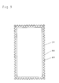
- the lower heating device 7 has a frame 33 resting against the edge 32 of the workpiece 3 to be heated.
- This frame 33 essentially surrounds the hot air distributor 31 and protrudes somewhat above its surface 34 on the workpiece side. This creates a flat chamber 35 between the underside of the workpiece 3 and the surface 34 of the hot air distributor 31, in which there is hot air under excess pressure. From here, the hot air either flows directly into the air-permeable workpiece 3 or initially through the heavily perforated conveyor belt 12 and finally into the upper heating device 6, which sucks the hot air emerging from the upper side 30 of the workpiece 3.
- the upper heating device 6 is also provided with an identically designed collector 36 corresponding to the hot air distributor 31 of the lower heating device 7. Furthermore, a frame 37 corresponding to the frame 33 surrounds the collector 36.
- the hot air circuit is switched off and the upper one
- the heating device 6 is only subjected to negative pressure or a permanent vacuum from the blower 26, so that the heating device 6 can also serve as a carrier for an air-permeable workpiece 3.
- This cooling device 38 comprises channels 39 for a coolant arranged in the lower and / or upper heating device 6, 7 or in their contact heating plates 18, 19.
- This coolant can be water, oil or the like.
- the channels 39 for the coolant in the contact heating plates 18, 19 are expediently controllable or individually controllable. This makes it possible to regulate the temperature in individual areas of the contact heating plate 18 or 19 to different heights.
- the frame or frames 33, 37 can also be used to protect the edge or the edges 40 of the workpiece 3 from heating.
- the workpiece 3 is thus not only fixable between the two heating devices 6, 7 with the aid of the respective frames 33, 37 at a distance from the hot air distributor 31 or collector 36, but the frames 33, 37 also have a further function in that the edge 40 of the workpiece 3 heats up less and thus also a greater strength retains than the other parts of the workpiece 3. This higher strength is desirable in many cases, namely when the workpiece 3 in the forming station 5 is taken over by the gripping devices 10, 11 located there.
- the contact heating plates 18, 19 move towards one another again and for this purpose are preferably mounted on springs not shown in the figures.
- the contact heating plates 18, 19 can slowly spring together.
- the springs are also preferably relatively soft.
- the embodiment according to FIG. 7 differs from the exemplary embodiment described first only in that a device 50 suitable for pure vacuum deformation is arranged in the forming station 5 instead of a lower mold 13 and an upper mold.
- This device 50 consists of a female or male 51, a vacuum box 52 and a frame 53 which can be lowered onto the free edge 54 of the vacuum box 52 and is used there for fixing the heated workpiece 3.
- the vacuum deformation takes place in the device 50 in a basically known manner.
- a suitable adjusting device 55 lowers the frame 53 from a rest position according to FIG. 7 above the level of the movable heating device 6 and presses the workpiece 3 with its edge 40 onto the free edge 53 of the vacuum box 52.
- the die or patrix 51 is then subjected to vacuum in a manner known per se with the aid of a blower 56, so that the atmospheric air pressure presses the workpiece 3 onto the surface of the die or patrix 51 and thus brings about the desired deformation.
- Pressing devices or the like working with overpressure can also be used in principle.
- the two gripping devices 10, 11 are preferably needle grippers 60 according to FIGS. 10 and 11 or needle grippers 90 according to FIGS. 12 and 13.
- Each of the needle grippers 60 has at least one needle 61, but preferably a plurality of needles 61, as shown in Fig. 10.
- the needles 61 are arranged on a needle carrier 62. Furthermore, the needles 61 are straight and relatively short.
- the needle gripper 60 further comprises at least one, but according to the exemplary embodiment two adjustment elements 63 and 64.
- the two adjustment elements 63, 64 are each pivotably articulated at their one end 65 or 66 at a fixed point 67 or 68. Furthermore, the two adjusting elements 63, 64 can be telescoped or their length can be changed.
- the two adjustment elements 63, 64 also connected to each other at their other ends 69, 7o by means of a spacer 71, this spacer 71 being pivoted at the respective ends 69,7o.
- the length of the spacer 71 is basically rigid, but can also be changed for the purpose of adjustment. 11, the distance between the two articulation points or fixed points 67, 68 is somewhat larger than the length of the spacer 71.
- the distance between the two fixed points 67 and 68 can also be changed for the purpose of adjustment and in the respective operating position with the help a setting shoe 72 and fixable with the aid of screws 73 on a support 74.
- Support 74 is supported by springs 74a and is longitudinally displaceable on guide rods 74b which are arranged on the bottom on a shoe 74c which engages in a dovetail guide 74d.
- the shoe 74c can be fastened there using screws.
- the carrier 74 is therefore also adjustable together with the two adjusting elements 63 and 64 along the dovetail guide 74d.
- a support 75 with an adjustable stop 76 is arranged on the carrier 74, which limits the possible pivoting movement of the one adjusting element 64 about the fixed point 68 between two stop points 77 and 78.
- the two adjustment elements 63, 64 are preferably piston-cylinder devices, the cylinders being articulated with their ends facing away from the piston rods 79, 80 at the fixed or pivot points 67, 68.
- the one adjusting element 64 or the corresponding piston-cylinder device carries at the free, telescopic end 70 a bearing piece 81 which carries the needle carrier 62 freely pivotable. With its axis 82, the needle carrier 62 is displaceable in the bearing piece 81 in the axial direction. Furthermore, a spring 83 supported on the bearing piece 81 acts on the needle carrier 62, so that the latter is displaced by the spring 83 into a basic position, from this basic position against the force of the spring 83, however, relative to the axis 84 of the adjusting element 64 or perpendicular to the axis 82 the corresponding piston-cylinder device is displaceable. With its needle carrier 62, the needle gripper can therefore follow deformations or changes in position occurring in the lateral direction in the event of tensile stress on the workpiece 3.
- the needle carrier 62 is also connected via arms or a fork formed by these to the spacer 71, which is articulated in a joint 86 on the free end 69 of the other adjusting element 63 or on the piston rod 79 of the corresponding piston-cylinder device.
- the position of the free end 69 of the adjusting element 63 or the respective position of the joint 86 therefore also determines the position and inclination of the needle carrier 62 and its needles 61.
- a change in position of the joint 86 caused by the adjusting element 63 causes a corresponding change in position or inclination of the needle carrier 62 and the needles 61.
- the possible adjustment and change in position of the joint 86 is limited by a fork 87 at the free end 70 of the adjusting element 64.
- the fork 87 serves as a stop for the spacer 71, which according to FIG. 11 lies in a slot in the fork 87.
- the cylinders of the two adjusting elements 63 and 64 can be controlled separately, so that the two piston rods 79, 80 can also be adjusted individually or together.
- the stroke of the two piston rods 79, 80 is different, and finally the actuation of the adjusting elements 63, 64 is also such that the piston rods 79, 80 can move at different speeds.
- necessary throttling and control elements are provided in the pressure supply lines for the adjusting elements 63, 64, which are basically known.
- the needles 61 on the needle carrier 62 are pressed upward into the workpiece 3 from below, whereupon the piston rod 79 of the adjusting element 63 is retracted slightly, so that the needle carrier 62 is rotated counterclockwise about the axis 82 pivots and further the needle carrier 62 is moved to the left in FIG. 11 together with the adjusting element 64 carrying it.
- the needling is thus carried out by extending the piston rods 79, 80 and then retracting the piston rod 79.
- both piston rods 79, 80 are retracted until the adjusting element 64 is prevented from moving further at the stop point 78 of the stop 76.
- the necessary stroke of the piston rod 79 is greater than that of the piston rod 80 overall in each operation.
- the needle carrier 62 is again pivoted with the aid of the adjusting element 63 and, furthermore, both piston rods 79, 80 are retracted or extended so far that the respectively desired level is reached.
- the frame 37 on the movable heating device 6 is expediently adapted to the needling of the workpiece 3 by the needle carrier 62.
- it has recesses 89 on its outside. These recesses 89 give the frame 37 a rake-like contour and enable the needles 61 to penetrate into the material of the workpiece 3 at a short distance from its outer edge.
- the needles first reach through the workpiece and then lie with their tips in the area of the recesses 89.
- Gripping devices 10 and 11 or needle grippers 60 are arranged in the forming station 5 on all sides of the workpiece 3, the needle carriers 62 being movable in a total of three directions X, Y and Z which overlap at the same time.
- the needle gripper 9o has only one telescopic or length-adjustable adjusting element 91 and not two adjusting elements like the needle gripper 6o.
- the adjusting element 91 is in turn preferably a piston-cylinder device.
- the adjusting element 91 carries one or more needles 93 which are angled in the tensioning direction with respect to the axis 94 of the piston rod 95 causing the movement.
- a needled workpiece cannot therefore come loose automatically.
- the adjusting element 91 is at its second end 96, i.e. supported at the lower end of the cylinder device 97 so as to be pivotable about an axis 98. Near the lower end 96, an arm 99 also projects away from the cylinder device 97 and has an adjusting element 100.
- the adjusting element 91 can perform pivoting movements towards and away from the forming tools 1o1 and 1o2 about its bearing point or about the axis 98 arranged on the bottom. This is driven by an inflatable and deflatable hose 1o3 and a reset element 1o4 e.g. in the form of a pressure membrane 1o4, which acts on the arm 99.
- the hose 1o3 serving as a swivel drive for the adjusting element 91 abuts the adjusting element 91 on the one hand and is supported on the lower mold 1o2 on the other hand and is preferably also fastened there.
- the hose 1o3 is a piece of hose and can have any length, so that it is not only one Adjustment element 91 abuts, but on several and possibly even on several sides of the molding tool 1o2.
- the adjusting element 91 is arranged essentially standing close to the circumference 1o5 of the lower molding tool 1o2 and can only be pivoted within a small angular range, as can be seen in FIG. 13 in solid or dashed lines according to the two representations.
- the stroke in the swivel direction is limited by the pressure membrane 1o4, which is e.g. can also act as a rubber buffer or the like, as well as through the setting element 100 on the arm 99, which cooperates with the pressure membrane 104 when setting the swivel stroke.
- the tip of the needle 93 in the single-needle position according to FIG. 12 is inclined slightly away from the molding tools 1o1 and 1o2.
- the storage of the lower end 96 of the adjusting element 91 and the arrangement of the pressure membrane 1o4 take place, for example, on a base plate 1o6 of the lower mold 1o2.
- the hose 1o3 can be arranged partially recessed in a recess 1o7 on the circumference 1o5 of the lower mold 1o2.
- the control and supply of the hose 1o3 with a pressure medium are not shown in the figures, since these are basically familiar elements.
Landscapes
- Engineering & Computer Science (AREA)
- Mechanical Engineering (AREA)
- Physics & Mathematics (AREA)
- Thermal Sciences (AREA)
- Blow-Moulding Or Thermoforming Of Plastics Or The Like (AREA)
- Moulds For Moulding Plastics Or The Like (AREA)
Applications Claiming Priority (2)
| Application Number | Priority Date | Filing Date | Title |
|---|---|---|---|
| DE4010441A DE4010441C2 (de) | 1990-03-31 | 1990-03-31 | Vorrichtung zum Herstellen eines Formteils aus einem verformbaren Werkstück |
| DE4010441 | 1990-03-31 |
Publications (2)
| Publication Number | Publication Date |
|---|---|
| EP0450482A2 true EP0450482A2 (fr) | 1991-10-09 |
| EP0450482A3 EP0450482A3 (en) | 1993-08-11 |
Family
ID=6403503
Family Applications (1)
| Application Number | Title | Priority Date | Filing Date |
|---|---|---|---|
| EP19910104849 Withdrawn EP0450482A3 (en) | 1990-03-31 | 1991-03-27 | Apparatus with a heating station and a forming station |
Country Status (5)
| Country | Link |
|---|---|
| EP (1) | EP0450482A3 (fr) |
| JP (1) | JP2583663B2 (fr) |
| KR (1) | KR910016464A (fr) |
| CN (1) | CN1055317A (fr) |
| DE (1) | DE4010441C2 (fr) |
Cited By (14)
| Publication number | Priority date | Publication date | Assignee | Title |
|---|---|---|---|---|
| EP0579937A1 (fr) * | 1992-07-18 | 1994-01-26 | Maschinenfabrik Georg Geiss | Machine de formage par le vide, pour former et souder, en mîme temps, deux feuilles en plastique |
| EP1099530A1 (fr) * | 1999-11-09 | 2001-05-16 | Tetra Laval Holdings & Finance Sa | Machine pour la production de récipients en matière plastique |
| EP1284182A3 (fr) * | 2001-08-13 | 2003-04-09 | R+S Technik GmbH | Procédé et appareil pour thermoformer des pièces avec imprimés à la surface |
| EP1304201A1 (fr) * | 2001-10-17 | 2003-04-23 | Persico S.p.A. | Installation pour le préchauffage de matériaux thermoformables poreux et méthode de préssage |
| EP1386709A1 (fr) * | 2002-07-22 | 2004-02-04 | Maschinenfabrik J. Dieffenbacher GmbH & Co. | Procédé et appareil pour soulever un cordon de matière plastique |
| EP1410895A1 (fr) * | 2002-10-16 | 2004-04-21 | ELKOM-Elektroheizplatten-Technik GmbH | Dispositif pour thermoformage forme avec une membrane et système de chauffage ou réfroidissement |
| WO2004069522A1 (fr) * | 2003-02-05 | 2004-08-19 | G.M.P. Spa | Installation integree de production d'articles de polyurethane renforce, procede associe et articles de polyurethane, ainsi obtenus |
| EP1522397A1 (fr) * | 2003-10-10 | 2005-04-13 | Adolf Illig GmbH & Co. KG | Appareil pour le formage des plaques ou sections d'une bande de film thermoplastiques chauffées |
| DE102004003742A1 (de) * | 2004-01-23 | 2005-08-18 | Gerd Weinrich | Vorwärmvorrichtung für flächige Materialienabschnitte |
| DE102004060965A1 (de) * | 2004-12-17 | 2006-06-22 | Rehau Ag + Co. | Vorrichtung und Verfahren zur Herstellung von Hohl-Formteilen |
| US7101503B2 (en) | 2002-02-15 | 2006-09-05 | R + S Technik Gmbh | Molding method and apparatus with plural cooperating mold tools for forming interior trim components for motor vehicles |
| EP1935600A1 (fr) * | 2006-12-20 | 2008-06-25 | Schmidt & Heinzmann GmbH & Co. KG | Dispositif doté d'un dispositif de levage |
| EP3124204A1 (fr) | 2015-07-31 | 2017-02-01 | Nabuurs Developing S.L. | Moule destine a la deformation thermique de composants |
| CN107263849A (zh) * | 2017-07-25 | 2017-10-20 | 佛山市乐华恒业卫浴有限公司 | 一种用于一体缸的成型设备 |
Families Citing this family (12)
| Publication number | Priority date | Publication date | Assignee | Title |
|---|---|---|---|---|
| DE19527691C2 (de) * | 1994-11-25 | 1999-05-06 | Rehau Ag & Co | Verfahren zur Herstellung von Formteilen |
| DE29713665U1 (de) * | 1997-07-31 | 1998-12-17 | Frimo Huber Systemtechnik Gmbh | Vorrichtung zum thermischen Formen von Kunststoffolien |
| KR20040021918A (ko) * | 2002-09-05 | 2004-03-11 | 명재권 | 일회용 원두커피캡슐플레이트의 제작장치 및원두커피캡슐플레이트 |
| DE102009007703B4 (de) * | 2009-02-05 | 2019-08-29 | Daimler Ag | Verfahren zum Herstellen eines Kunststoffbauteils mit Verstärkungsstruktur |
| CN103057103B (zh) * | 2012-12-24 | 2015-02-04 | 潘震州 | 一种厚卷板材成型机 |
| KR102309386B1 (ko) * | 2015-01-20 | 2021-10-06 | 삼성디스플레이 주식회사 | 윈도우 가공 장치 |
| DE102015101668A1 (de) * | 2015-02-05 | 2016-08-11 | Benteler Automobiltechnik Gmbh | Zweifach fallendes Heiz- und Formwerkzeug sowie Verfahren zur Herstellung warmumgeformter und pressgehärteter Kraftfahrzeugbauteile |
| JP6364376B2 (ja) * | 2015-04-20 | 2018-07-25 | 三井屋工業株式会社 | 搬送装置 |
| CN105643907A (zh) * | 2016-03-09 | 2016-06-08 | 东莞市宏浩包装机械有限公司 | 一种可直接定型的吸塑成型或气压成型设备 |
| CN107303622A (zh) * | 2016-04-20 | 2017-10-31 | 张跃 | 一种夹式钎焊装置及其使用方法 |
| CN107303620A (zh) * | 2016-04-20 | 2017-10-31 | 张跃 | 一种夹式连续铜钎焊流水线 |
| CN110181798A (zh) * | 2019-05-29 | 2019-08-30 | 江苏师范大学 | 一种塑料板加热装置 |
Citations (6)
| Publication number | Priority date | Publication date | Assignee | Title |
|---|---|---|---|---|
| US2926385A (en) * | 1953-08-06 | 1960-03-01 | Plax Corp | Sheet shaping |
| FR2078575A5 (fr) * | 1970-02-12 | 1971-11-05 | Mahaffy Harder Engineeri | |
| FR2421719A1 (fr) * | 1977-11-03 | 1979-11-02 | Osoboe Ok | Installation pour la fabrication de pieces a partir de feuilles en matiere thermoplastique |
| DE3103584A1 (de) * | 1981-02-03 | 1982-08-12 | Paul Kiefel Gmbh, 8228 Freilassing | Verfahren und thermoformmaschine zum formen von thermoplastischen platten, folien o.dgl. |
| EP0063462A1 (fr) * | 1981-04-15 | 1982-10-27 | M.L. Shelley & Partners Limited | Dispositif de thermoformage |
| EP0148762A2 (fr) * | 1984-01-06 | 1985-07-17 | The Wiggins Teape Group Limited | Objets moulés en matière plastique renforcée de fibres |
Family Cites Families (4)
| Publication number | Priority date | Publication date | Assignee | Title |
|---|---|---|---|---|
| US3910747A (en) * | 1974-09-23 | 1975-10-07 | Formex Mfg Inc | Apparatus having improved sheet clamping means for forming plastic sheets |
| DE2743184C3 (de) * | 1977-09-26 | 1981-03-12 | Osoboe opytno-konstruktorskoe bjuro po razvitiju mechanopnevmatičeskoj technologii pererabotki listovych termoplastov, Leningrad | Vorrichtung zur Herstellung von Gegenständen aus blattförmigem thermoplstischem Material mit einer Heizvorrichtung für dieses, die aus zwei Luftkästen besteht |
| DE3435188C2 (de) * | 1984-09-25 | 1986-10-02 | Multivac Sepp Haggenmüller KG, 8941 Wolfertschwenden | Heizeinrichtung zum Erwärmen einer Folie vor deren Warmverformen |
| JPS6437255A (en) * | 1987-08-04 | 1989-02-07 | Riken Chemical Ind | Gum for oral sterilization |
-
1990
- 1990-03-31 DE DE4010441A patent/DE4010441C2/de not_active Expired - Fee Related
- 1990-07-30 KR KR1019900011631A patent/KR910016464A/ko not_active Application Discontinuation
- 1990-07-31 CN CN90106558A patent/CN1055317A/zh active Pending
- 1990-10-31 JP JP2296749A patent/JP2583663B2/ja not_active Expired - Lifetime
-
1991
- 1991-03-27 EP EP19910104849 patent/EP0450482A3/de not_active Withdrawn
Patent Citations (6)
| Publication number | Priority date | Publication date | Assignee | Title |
|---|---|---|---|---|
| US2926385A (en) * | 1953-08-06 | 1960-03-01 | Plax Corp | Sheet shaping |
| FR2078575A5 (fr) * | 1970-02-12 | 1971-11-05 | Mahaffy Harder Engineeri | |
| FR2421719A1 (fr) * | 1977-11-03 | 1979-11-02 | Osoboe Ok | Installation pour la fabrication de pieces a partir de feuilles en matiere thermoplastique |
| DE3103584A1 (de) * | 1981-02-03 | 1982-08-12 | Paul Kiefel Gmbh, 8228 Freilassing | Verfahren und thermoformmaschine zum formen von thermoplastischen platten, folien o.dgl. |
| EP0063462A1 (fr) * | 1981-04-15 | 1982-10-27 | M.L. Shelley & Partners Limited | Dispositif de thermoformage |
| EP0148762A2 (fr) * | 1984-01-06 | 1985-07-17 | The Wiggins Teape Group Limited | Objets moulés en matière plastique renforcée de fibres |
Cited By (21)
| Publication number | Priority date | Publication date | Assignee | Title |
|---|---|---|---|---|
| EP0579937A1 (fr) * | 1992-07-18 | 1994-01-26 | Maschinenfabrik Georg Geiss | Machine de formage par le vide, pour former et souder, en mîme temps, deux feuilles en plastique |
| EP1099530A1 (fr) * | 1999-11-09 | 2001-05-16 | Tetra Laval Holdings & Finance Sa | Machine pour la production de récipients en matière plastique |
| US6358032B1 (en) | 1999-11-09 | 2002-03-19 | Tetra Laval Holdings & Finance Sa | Machine for the production of plastic receptacles |
| EP1284182A3 (fr) * | 2001-08-13 | 2003-04-09 | R+S Technik GmbH | Procédé et appareil pour thermoformer des pièces avec imprimés à la surface |
| US6749794B2 (en) | 2001-08-13 | 2004-06-15 | R + S Technik Gmbh | Method and apparatus for molding components with molded-in surface texture |
| EP1304201A1 (fr) * | 2001-10-17 | 2003-04-23 | Persico S.p.A. | Installation pour le préchauffage de matériaux thermoformables poreux et méthode de préssage |
| US7101503B2 (en) | 2002-02-15 | 2006-09-05 | R + S Technik Gmbh | Molding method and apparatus with plural cooperating mold tools for forming interior trim components for motor vehicles |
| EP1386709A1 (fr) * | 2002-07-22 | 2004-02-04 | Maschinenfabrik J. Dieffenbacher GmbH & Co. | Procédé et appareil pour soulever un cordon de matière plastique |
| US7353934B2 (en) | 2002-07-22 | 2008-04-08 | Maschinenfabrik J. Dieffenbacher Gmbh & Co. | Method and apparatus for picking up a plastic product |
| EP1410895A1 (fr) * | 2002-10-16 | 2004-04-21 | ELKOM-Elektroheizplatten-Technik GmbH | Dispositif pour thermoformage forme avec une membrane et système de chauffage ou réfroidissement |
| WO2004069522A1 (fr) * | 2003-02-05 | 2004-08-19 | G.M.P. Spa | Installation integree de production d'articles de polyurethane renforce, procede associe et articles de polyurethane, ainsi obtenus |
| EP1522397A1 (fr) * | 2003-10-10 | 2005-04-13 | Adolf Illig GmbH & Co. KG | Appareil pour le formage des plaques ou sections d'une bande de film thermoplastiques chauffées |
| DE102004003742A1 (de) * | 2004-01-23 | 2005-08-18 | Gerd Weinrich | Vorwärmvorrichtung für flächige Materialienabschnitte |
| DE102004060965A1 (de) * | 2004-12-17 | 2006-06-22 | Rehau Ag + Co. | Vorrichtung und Verfahren zur Herstellung von Hohl-Formteilen |
| EP1935600A1 (fr) * | 2006-12-20 | 2008-06-25 | Schmidt & Heinzmann GmbH & Co. KG | Dispositif doté d'un dispositif de levage |
| US7891967B2 (en) | 2006-12-20 | 2011-02-22 | Schmidt & Heinzmann Gmbh & Co. Kg | Apparatus having a lifting apparatus |
| EP3124204A1 (fr) | 2015-07-31 | 2017-02-01 | Nabuurs Developing S.L. | Moule destine a la deformation thermique de composants |
| DE102015112641A1 (de) | 2015-07-31 | 2017-02-02 | Nabuurs Developing S.L. | Formeinrichtung zur thermischen Umformung von Bauteilen |
| US9981409B2 (en) | 2015-07-31 | 2018-05-29 | Nabuurs Developing S. L. | Forming device for thermoforming components |
| CN107263849A (zh) * | 2017-07-25 | 2017-10-20 | 佛山市乐华恒业卫浴有限公司 | 一种用于一体缸的成型设备 |
| CN107263849B (zh) * | 2017-07-25 | 2023-07-21 | 箭牌家居集团股份有限公司 | 一种用于一体缸的成型设备 |
Also Published As
| Publication number | Publication date |
|---|---|
| DE4010441A1 (de) | 1991-10-02 |
| KR910016464A (ko) | 1991-11-05 |
| CN1055317A (zh) | 1991-10-16 |
| DE4010441C2 (de) | 1994-10-20 |
| JPH03284933A (ja) | 1991-12-16 |
| JP2583663B2 (ja) | 1997-02-19 |
| EP0450482A3 (en) | 1993-08-11 |
Similar Documents
| Publication | Publication Date | Title |
|---|---|---|
| EP0450482A2 (fr) | Dispositif avec un poste de chauffage et un poste de formation | |
| EP1436140B1 (fr) | Procede et dispositif pour manipuler de facon automatisee des mats impregnes de resine lors de la production de pieces en smc | |
| DE10035237C1 (de) | Verfahren und Produktionsanlage zum Herstellen von schalenförmigen, fasermatten-verstärkten Kunststoffteilen | |
| EP3538351A1 (fr) | Procédé et dispositif de fabrication additive d'une pièce tridimensionnelle | |
| DE3807164C2 (fr) | ||
| DE4206262A1 (de) | Verfahren zum verschweissen von halogenfreien thermoplastfolien | |
| EP2803471B1 (fr) | Machine d'usinage pour le thermoformage d'une pièce à déformation thermoplastique | |
| DE3216332C2 (de) | Vorrichtung zum Herstellen eines dreidimensional geformten Schichtkörpers aus einer kompakten Kunststoffschicht und einer angeschäumten Schaumstoffschicht | |
| DE3827497A1 (de) | Vorrichtung zur beschichtung von dreidimensionalen koerpern mit einer folie | |
| DE102011055141B4 (de) | Folienentfernvorrichtung und Verfahren zum Entfernen einer Folie von Objekten | |
| DE60312008T2 (de) | Anlage zur herstellung von objekten durch wärmeformen von kügelchen aus thermoplastischem material | |
| DE102013103653B4 (de) | Verfahren zur fertigung eines kunststoffteils und gerät zudessen durchführung sowie resultierendeskunststoffprodukt | |
| WO2017129806A1 (fr) | Outil de drapage d'une découpe fibreuse et procédé de fabrication d'une ébauche tridimensionnelle | |
| DE112013006092T5 (de) | Anlage und Verfahren zur Herstellung eines Werkstücks aus Thermoplast | |
| EP0914934A1 (fr) | Procédé pour l'emboutissage de matières | |
| DE2328368B2 (de) | Thermoformvorrichtung zum herstellen von formlingen grosser tiefe aus einem relativ dicken kunststoffband | |
| DE4338301C2 (de) | Vorrichtung zur Herstellung von profilierten Kunststoff-Hohlteilen | |
| EP1025978B1 (fr) | Dispositif de thermoformage de récipients à partir d'un film thermoplastique | |
| DE19853660C2 (de) | Vorrichtung und Verfahren zum Kaschieren | |
| EP0787111A1 (fr) | Procede de fabrication d'articles moules en verre, par moulage par compression et dispositif specialement approprie pour la mise en uvre de ce procede | |
| DE2931715C2 (de) | Formwerkzeug zur Herstellung von Membranen | |
| DE2504440C3 (de) | Vorrichtung zum Tiefziehen von Werkstücken aus thermoplastischer Kunststoffolie | |
| DE2054437C3 (de) | Umformanlage zum Verarbeiten von Platten oder Folien aus thermoplastischem Kunststoff | |
| DE4028589C2 (de) | Nadelvorrichtung zum Übernehmen und Halten von flächigen Werkstücken aus thermoplastischem Kunststoff | |
| DE3435859A1 (de) | Vorrichtung und verfahren zum formen von buestenteilen |
Legal Events
| Date | Code | Title | Description |
|---|---|---|---|
| PUAI | Public reference made under article 153(3) epc to a published international application that has entered the european phase |
Free format text: ORIGINAL CODE: 0009012 |
|
| AK | Designated contracting states |
Kind code of ref document: A2 Designated state(s): AT BE CH DE DK ES FR GB GR IT LI LU NL SE |
|
| RBV | Designated contracting states (corrected) |
Designated state(s): AT BE DE ES FR GB IT SE |
|
| PUAL | Search report despatched |
Free format text: ORIGINAL CODE: 0009013 |
|
| AK | Designated contracting states |
Kind code of ref document: A3 Designated state(s): AT BE CH DE DK ES FR GB GR IT LI LU NL SE |
|
| 17P | Request for examination filed |
Effective date: 19930810 |
|
| 17Q | First examination report despatched |
Effective date: 19941219 |
|
| STAA | Information on the status of an ep patent application or granted ep patent |
Free format text: STATUS: THE APPLICATION HAS BEEN WITHDRAWN |
|
| 18W | Application withdrawn |
Withdrawal date: 19950223 |