EP0448239B1 - Machine comportant des paliers à compensation thermique - Google Patents
Machine comportant des paliers à compensation thermique Download PDFInfo
- Publication number
- EP0448239B1 EP0448239B1 EP91301618A EP91301618A EP0448239B1 EP 0448239 B1 EP0448239 B1 EP 0448239B1 EP 91301618 A EP91301618 A EP 91301618A EP 91301618 A EP91301618 A EP 91301618A EP 0448239 B1 EP0448239 B1 EP 0448239B1
- Authority
- EP
- European Patent Office
- Prior art keywords
- case
- bearings
- ring
- cup
- insert
- Prior art date
- Legal status (The legal status is an assumption and is not a legal conclusion. Google has not performed a legal analysis and makes no representation as to the accuracy of the status listed.)
- Revoked
Links
Images


Classifications
-
- F—MECHANICAL ENGINEERING; LIGHTING; HEATING; WEAPONS; BLASTING
- F16—ENGINEERING ELEMENTS AND UNITS; GENERAL MEASURES FOR PRODUCING AND MAINTAINING EFFECTIVE FUNCTIONING OF MACHINES OR INSTALLATIONS; THERMAL INSULATION IN GENERAL
- F16C—SHAFTS; FLEXIBLE SHAFTS; ELEMENTS OR CRANKSHAFT MECHANISMS; ROTARY BODIES OTHER THAN GEARING ELEMENTS; BEARINGS
- F16C25/00—Bearings for exclusively rotary movement adjustable for wear or play
- F16C25/06—Ball or roller bearings
- F16C25/08—Ball or roller bearings self-adjusting
-
- F—MECHANICAL ENGINEERING; LIGHTING; HEATING; WEAPONS; BLASTING
- F16—ENGINEERING ELEMENTS AND UNITS; GENERAL MEASURES FOR PRODUCING AND MAINTAINING EFFECTIVE FUNCTIONING OF MACHINES OR INSTALLATIONS; THERMAL INSULATION IN GENERAL
- F16C—SHAFTS; FLEXIBLE SHAFTS; ELEMENTS OR CRANKSHAFT MECHANISMS; ROTARY BODIES OTHER THAN GEARING ELEMENTS; BEARINGS
- F16C19/00—Bearings with rolling contact, for exclusively rotary movement
- F16C19/22—Bearings with rolling contact, for exclusively rotary movement with bearing rollers essentially of the same size in one or more circular rows, e.g. needle bearings
- F16C19/34—Bearings with rolling contact, for exclusively rotary movement with bearing rollers essentially of the same size in one or more circular rows, e.g. needle bearings for both radial and axial load
- F16C19/36—Bearings with rolling contact, for exclusively rotary movement with bearing rollers essentially of the same size in one or more circular rows, e.g. needle bearings for both radial and axial load with a single row of rollers
- F16C19/364—Bearings with rolling contact, for exclusively rotary movement with bearing rollers essentially of the same size in one or more circular rows, e.g. needle bearings for both radial and axial load with a single row of rollers with tapered rollers, i.e. rollers having essentially the shape of a truncated cone
-
- F—MECHANICAL ENGINEERING; LIGHTING; HEATING; WEAPONS; BLASTING
- F16—ENGINEERING ELEMENTS AND UNITS; GENERAL MEASURES FOR PRODUCING AND MAINTAINING EFFECTIVE FUNCTIONING OF MACHINES OR INSTALLATIONS; THERMAL INSULATION IN GENERAL
- F16C—SHAFTS; FLEXIBLE SHAFTS; ELEMENTS OR CRANKSHAFT MECHANISMS; ROTARY BODIES OTHER THAN GEARING ELEMENTS; BEARINGS
- F16C19/00—Bearings with rolling contact, for exclusively rotary movement
- F16C19/52—Bearings with rolling contact, for exclusively rotary movement with devices affected by abnormal or undesired conditions
- F16C19/525—Bearings with rolling contact, for exclusively rotary movement with devices affected by abnormal or undesired conditions related to temperature and heat, e.g. insulation
-
- F—MECHANICAL ENGINEERING; LIGHTING; HEATING; WEAPONS; BLASTING
- F16—ENGINEERING ELEMENTS AND UNITS; GENERAL MEASURES FOR PRODUCING AND MAINTAINING EFFECTIVE FUNCTIONING OF MACHINES OR INSTALLATIONS; THERMAL INSULATION IN GENERAL
- F16C—SHAFTS; FLEXIBLE SHAFTS; ELEMENTS OR CRANKSHAFT MECHANISMS; ROTARY BODIES OTHER THAN GEARING ELEMENTS; BEARINGS
- F16C19/00—Bearings with rolling contact, for exclusively rotary movement
- F16C19/54—Systems consisting of a plurality of bearings with rolling friction
- F16C19/546—Systems with spaced apart rolling bearings including at least one angular contact bearing
- F16C19/547—Systems with spaced apart rolling bearings including at least one angular contact bearing with two angular contact rolling bearings
- F16C19/548—Systems with spaced apart rolling bearings including at least one angular contact bearing with two angular contact rolling bearings in O-arrangement
-
- F—MECHANICAL ENGINEERING; LIGHTING; HEATING; WEAPONS; BLASTING
- F16—ENGINEERING ELEMENTS AND UNITS; GENERAL MEASURES FOR PRODUCING AND MAINTAINING EFFECTIVE FUNCTIONING OF MACHINES OR INSTALLATIONS; THERMAL INSULATION IN GENERAL
- F16C—SHAFTS; FLEXIBLE SHAFTS; ELEMENTS OR CRANKSHAFT MECHANISMS; ROTARY BODIES OTHER THAN GEARING ELEMENTS; BEARINGS
- F16C33/00—Parts of bearings; Special methods for making bearings or parts thereof
- F16C33/30—Parts of ball or roller bearings
- F16C33/58—Raceways; Race rings
- F16C33/583—Details of specific parts of races
- F16C33/586—Details of specific parts of races outside the space between the races, e.g. end faces or bore of inner ring
-
- F—MECHANICAL ENGINEERING; LIGHTING; HEATING; WEAPONS; BLASTING
- F16—ENGINEERING ELEMENTS AND UNITS; GENERAL MEASURES FOR PRODUCING AND MAINTAINING EFFECTIVE FUNCTIONING OF MACHINES OR INSTALLATIONS; THERMAL INSULATION IN GENERAL
- F16H—GEARING
- F16H3/00—Toothed gearings for conveying rotary motion with variable gear ratio or for reversing rotary motion
- F16H3/02—Toothed gearings for conveying rotary motion with variable gear ratio or for reversing rotary motion without gears having orbital motion
- F16H3/08—Toothed gearings for conveying rotary motion with variable gear ratio or for reversing rotary motion without gears having orbital motion exclusively or essentially with continuously meshing gears, that can be disengaged from their shafts
- F16H3/087—Toothed gearings for conveying rotary motion with variable gear ratio or for reversing rotary motion without gears having orbital motion exclusively or essentially with continuously meshing gears, that can be disengaged from their shafts characterised by the disposition of the gears
- F16H3/089—Toothed gearings for conveying rotary motion with variable gear ratio or for reversing rotary motion without gears having orbital motion exclusively or essentially with continuously meshing gears, that can be disengaged from their shafts characterised by the disposition of the gears all of the meshing gears being supported by a pair of parallel shafts, one being the input shaft and the other the output shaft, there being no countershaft involved
-
- F—MECHANICAL ENGINEERING; LIGHTING; HEATING; WEAPONS; BLASTING
- F16—ENGINEERING ELEMENTS AND UNITS; GENERAL MEASURES FOR PRODUCING AND MAINTAINING EFFECTIVE FUNCTIONING OF MACHINES OR INSTALLATIONS; THERMAL INSULATION IN GENERAL
- F16H—GEARING
- F16H3/00—Toothed gearings for conveying rotary motion with variable gear ratio or for reversing rotary motion
- F16H3/02—Toothed gearings for conveying rotary motion with variable gear ratio or for reversing rotary motion without gears having orbital motion
- F16H3/08—Toothed gearings for conveying rotary motion with variable gear ratio or for reversing rotary motion without gears having orbital motion exclusively or essentially with continuously meshing gears, that can be disengaged from their shafts
- F16H3/087—Toothed gearings for conveying rotary motion with variable gear ratio or for reversing rotary motion without gears having orbital motion exclusively or essentially with continuously meshing gears, that can be disengaged from their shafts characterised by the disposition of the gears
- F16H3/091—Toothed gearings for conveying rotary motion with variable gear ratio or for reversing rotary motion without gears having orbital motion exclusively or essentially with continuously meshing gears, that can be disengaged from their shafts characterised by the disposition of the gears including a single countershaft
- F16H3/0915—Toothed gearings for conveying rotary motion with variable gear ratio or for reversing rotary motion without gears having orbital motion exclusively or essentially with continuously meshing gears, that can be disengaged from their shafts characterised by the disposition of the gears including a single countershaft with coaxial input and output shafts
-
- F—MECHANICAL ENGINEERING; LIGHTING; HEATING; WEAPONS; BLASTING
- F16—ENGINEERING ELEMENTS AND UNITS; GENERAL MEASURES FOR PRODUCING AND MAINTAINING EFFECTIVE FUNCTIONING OF MACHINES OR INSTALLATIONS; THERMAL INSULATION IN GENERAL
- F16H—GEARING
- F16H57/00—General details of gearing
- F16H57/02—Gearboxes; Mounting gearing therein
- F16H57/021—Shaft support structures, e.g. partition walls, bearing eyes, casing walls or covers with bearings
-
- F—MECHANICAL ENGINEERING; LIGHTING; HEATING; WEAPONS; BLASTING
- F16—ENGINEERING ELEMENTS AND UNITS; GENERAL MEASURES FOR PRODUCING AND MAINTAINING EFFECTIVE FUNCTIONING OF MACHINES OR INSTALLATIONS; THERMAL INSULATION IN GENERAL
- F16C—SHAFTS; FLEXIBLE SHAFTS; ELEMENTS OR CRANKSHAFT MECHANISMS; ROTARY BODIES OTHER THAN GEARING ELEMENTS; BEARINGS
- F16C2202/00—Solid materials defined by their properties
- F16C2202/20—Thermal properties
- F16C2202/22—Coefficient of expansion
-
- F—MECHANICAL ENGINEERING; LIGHTING; HEATING; WEAPONS; BLASTING
- F16—ENGINEERING ELEMENTS AND UNITS; GENERAL MEASURES FOR PRODUCING AND MAINTAINING EFFECTIVE FUNCTIONING OF MACHINES OR INSTALLATIONS; THERMAL INSULATION IN GENERAL
- F16C—SHAFTS; FLEXIBLE SHAFTS; ELEMENTS OR CRANKSHAFT MECHANISMS; ROTARY BODIES OTHER THAN GEARING ELEMENTS; BEARINGS
- F16C2361/00—Apparatus or articles in engineering in general
- F16C2361/61—Toothed gear systems, e.g. support of pinion shafts
Definitions
- This invention relates in general to transmissions and transaxles and like machinery and more particularly to machinery of that character having bearings which are mounted to compensate for differential thermal expansion and contraction between cases and shafts.
- the input shaft has a pocket which receives the end of the output shaft, and here the output shaft is provided with another single row tapered roller bearing, known as a pocket bearing, which is also mounted directly with respect to the bearing for the output shaft.
- the input and output shafts carry gears which mesh with gears on a countershaft, and the countershaft at its ends is fitted with single row tapered roller bearings that are set into the case also in the direct configuration.
- a typical manual shift transaxle has an input shaft and a parallel countershaft which are likewise set in directly mounted tapered roller bearings that are fitted to the case, and tile countershaft is in turn coupled through gearing with the differential shaft.
- the tapered roller bearings carry extremely heavy loads for their size. Furthermore, they take axial or thrust loads as well as radial loads, and thus, a minimum number of bearings accommodate all of the loads to which the shafts are subjected. These characteristics serve to make transmissions equipped with tapered roller bearings highly compact.
- opposed tapered roller bearings should operate within an optimum setting range dictated by application requirements.
- the objective is to minimise axial and radial free motion in the shafts, for this maximises the bearing life, reduces noise, and improves gear mesh.
- the directly mounted bearings which support the aligned input and output shafts and the countershaft of the typical in-line transmission and the parallel input shaft, main shaft and differential shaft of the typical manual transaxle in effect capture those shafts axially. If the transmission or transaxle case were made from steel, like the shafts and bearings, the case and shafts and the bearings would expand similarly with temperature variations, and the settings of the bearings for each shaft would not change drastically over a wide range of temperatures.
- the aluminium alloys from which many cases for the transmission and transaxles of current manufacture are cast, have coefficients of thermal expansion greater than that of the steel from which the shafts and bearings are made. Assuming such a transmission of transaxle is assembled at room temperature with its directly mounted bearings in a condition of zero end play, the bearings will experience pre-load when the temperature drops, because the case contracts more than the shafts. By the same token, the bearings will experience end play as the temperature rises above room temperature, since the case expands more than the shafts.
- DE-A-3239305 describes the mounting of a shaft in a casing by means of tapered roller bearings.
- the back face of the outer race of one tapered roller bearing abuts a co-operating abutment of the casing through a temperature compensating ring so as to compensate for differential expansion of the casing and shaft with changes of temperature.
- a tapered roller bearing comprising a first race in the form of a cone having an outwardly presented tapered raceway and a back face located beyond the larger diameter end of the raceway; a second race in the form of a cup located around the cone and having an inwardly presented raceway and a back face at the smaller diameter end of the raceway, tapered rollers located in a single row between the raceways of the cup and cone, and a compensating ring disposed for abutment with one of said races for loading said one race axially against the other said race via said rollers, said ring being formed from a material having a high coefficient of thermal expansion, characterized in that said one race has a recess which provides a surface for locating the ring radially and an abutment or backing surface facing axially in the same direction as the back face of said one race, said ring being disposed in said recess and against said backing surface.
- a combination comprising a case having coaxial abutment faces for locating shaft means, shaft means in the case which shaft means has abutment faces respectively presented toward and spaced axially from the abutment faces of the case, the shaft means being formed from a material which has a different coefficient of thermal expansion from the material of the case, and at least two bearings supporting the shaft means in the case, the bearings being configured to accommodate both axial and radial loads and being each mounted in the case and on the shaft means between the abutment faces of the case and the shaft means where the abutment faces are in opposition to each other, so that the bearings confine the shaft means both axially and radially in the case, each bearing having inner and outer races being presented respectively opposite abutment faces on the shaft means and in the case, each of said bearings having mutually facing raceways and rolling elements which roll along the raceways, and a compensating ring disposed axially between at least one of said races and the abutment face opposite which
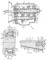
- a manually operated automotive transmission A ( Figure 1) includes a case 2 which is cast from a lightweight metal such as aluminium alloy.
- the transmission A also has an input shaft 4 and an output shaft 6 which are axially aligned along an axis x of rotation, the former projecting from one end of the case 2 and the latter from the other end.
- the transmission A has a countershaft 8 which is contained wholly within the case 2 where it rotates about an axis x parallel to the common axis x of the input and output shafts 4 and 6. All three of the shafts 4, 6 and 8 carry gears 10 which mesh in different combinations to produce different speed ratios between the input shaft 4 and the output shaft 6.
- the three shafts 4, 6 and 8 are machined from steel, as are the gears 10 on them.
- the input shaft 4 rotates in a single row tapered roller bearing 20 ( Figure 1) that fits around it and within a bore 22 in the wall at one end of the case 2, it being located between abutments, that is a shoulder 24 at the end of the bore 22 and another shoulder 26 on the shaft 4.
- the output shaft 6 rotates on another single row tapered roller bearing 30 ( Figures 1 and 2) located in a bore 32 at the opposite end wall of the case 2. It is also located between abutments in the form of a shoulder 34 at the end of the bore 32 and a backing face 36 on the shaft 6.
- the output shaft 6 at its end has a pilot 40 (Figure 1) which projects into a pocket 42 in the end of the input shaft 4.
- the pilot 40 is fitted with still another tapered roller bearing 44.
- the tapered roller bearings 20 and 30 are mounted in opposition in the direct configuration, that is, with the large ends of their tapered rollers presented inwardly toward each other.
- the tapered roller bearing 44 of the pocket 42 is mounted in the direct configuration with respect to the bearing 30 of the output shaft 6.
- the pocket bearing 44 enables the output shaft 6 to rotate relative to the input shaft 4, the two shafts 4 and 6 cannot move axially with respect to each other or with respect to the case 2, since the bearings 20 and 30 in effect capture them in the case 2. For purposes of the present invention, they are in effect one shaft.
- the countershaft 8 is housed entirely within the case 2, its ends being received in single row tapered roller bearings 48 and 50 (Figure 1) which are in turn received in bores 52 and 54 respectively, located in the end walls of the case 2. Indeed, the bore 52 lies below the bore 22 in which the bearing 20 for the input shaft 4 is located, whereas the bore 54 is located below the bore 32 in which the bearing 30 for the output shaft 6 is located.
- the countershaft 8 has abutments, that is shoulder 56, and the bearings 48 and 50 are captured between these shoulders and corresponding abutments or shoulders 58 at the ends of the bores 52 and 54 of the case 2.
- the bearings 48 and 50 in turn capture the countershaft 8 in the case 2 in the sense that they prevent the countershaft 8 from moving radially or axially in the case 2, yet they permit rotation of the shaft 8 with minimal frictional resistance.
- Each of the bearings 20, 30, 48 and 50 has an axis x of rotation which lies coincident with the axis x of the shaft 4, 6 or 8 which it supports, and being a single row tapered roller bearing, it includes ( Figure 2) a cone 60 which fits around one of the shafts 4, 6 or 8, a cup 62 which fits into one of the bores 22, 32, 52 or 54 and around the cone 60, tapered rollers 64 which are arranged in a single row between the cone 60 and cup 62, and a cage 66 for maintaining the proper spacing between the rollers 64.
- the cup 62 remains essentially stationary in the case 2, while the cone 60 rotates within it as its particular shaft 4, 6 or 8 turns about its axis x of rotation.
- the cone 60 has a bore 68 ( Figure 2) which is slightly smaller than the shaft 4, 6 or 8 over which the cone 60 fits, so that an interference fit exists between the cone 60 and its shaft. It also has a tapered raceway 70 which is presented outwardly toward the cup 62. The raceway 70 lies between a thrust rib 72 and a retaining rib 74, both of which project outwardly beyond the raceway 70. The two ends of the cone 60 are squared off with respect to the axis x of rotation, the end at the thrust rib 72 forming a cone back face 76.
- the cup 62 has an outwardly presented cylindrical surface 80 (Figure 2) which may be slightly smaller or slightly larger than the bore 22, 32, 52 or 54 into which it fits, depending on whether an interference or loose fit is desired.
- the cup 62 has a tapered raceway 82 which is presented inwardly toward the tapered raceway 70 of the cone 60. The ends of the cup 62 are squared off with respect to the axis x, the larger of the end faces, which is at the small end of the tapered raceway 82, forming a cup back face 84.
- the tapered rollers 64 lie in a single circumferential row between the raceways 70 and 82 of the cone 60 and cup 62 with their large end faces presented toward the thrust rib 72 of the cone 60 ( Figure 2).
- the thrust rib 72 prevents the rollers 64 from being expelled from the space between the two raceways 70 and 82 when a radial load is transmitted through the rollers 64.
- the rollers 64 are on apex, meaning that if the side faces of the rollers 64 were extended to their respective apexes, those apexes would lie at a common point along the axis x, and the same holds true with regard to the two raceways 70 and 82.
- the cone 60 of the bearing 20 fits tightly around the input shaft 4 with its back face 76 against the shoulder 26 ( Figure 1).
- the cup 62 of that bearing fits snugly in the bore 22 with its back face 84 against the shoulder 24.
- the cone 60 for the other bearing 30 fits snugly around the output shaft 6 with its back face 76 against the backing face 36
- the cup 62 of that bearing fits loosely in the bore 32 with its back face 84 presented toward but not contacting the shoulder 34 at the end of the bore 32.
- the cones 60 of the two bearings 48 and 50 for the countershaft 8 fit snugly around the countershaft 8 with their back faces against the shoulders 56 on the shaft 8.
- the cup 62 of the bearing 48 fits snugly within its bore 52 where its back face 84 is against the shoulder 58 at the end of the bore 52.
- the cup 62 of the bearing 50 fits loosely into the bore 54, and while its back face 84 is presented toward the shoulder 58 at the end of that bore, it does not actually contact the shoulder 58.
- each bearing 20, 30, 48 and 50 maintains a slight separation between adjacent rollers 64. It further holds the rollers 64 around the cone raceway 70 when the cone 60 is removed from the cup 62.
- the pocket bearing 44 is much the same as the other bearings 20, 30, 48 and 50, except that it is not located in a wall of the case 2, but is instead located in the end of the input shaft 4. Moreover, its cup may be an integral part of the input shaft 4, in which event its raceway 82 forms the pocket 42.
- the bearings 20, 30 and 44 being located along the common axis x of the input and output shafts 4 and 6, operate at a common setting, and that setting depends on the location of the cups 62 for the two bearings 20 and 30 that are in the case - or at least it is controlled by the location of those cups 62. For example, if the cups 62 are spread too far apart, the shafts 4 and 6 will be loose between those cups 62, or in other words, will be in a condition of end play. On the other hand, if the cups 62 are too close together, the bearings 20 and 30 and those portions of the shafts 4 and 6 that are between them, as well as the pocket bearing 44, will be in a state of compression or, in other words, in a condition of pre-load. Traditionally, the settings for the bearings of transmissions have been controlled with shims located between the back faces of the cups and the shoulders toward which those back faces are presented.
- the case 2 When subjected to temperature variations, the case 2, being formed from aluminium alloy, undergoes greater dimensional changes than the shafts 4 and 6, which are formed from steel. Indeed, aluminium alloy has about twice the coefficient of thermal expansion as does steel. Thus, an elevation in temperature will cause the end walls of the case 2 to spread farther apart and they of course will carry the shoulders 24 and 34, which locate the cups 62 of the two bearings 20 and 30, outwardly with them. The shafts 4 and 6 will also grow and this spreads the backing shoulders 26 and 36 on the aligned shafts 4 and 6 farther apart. However the increase in distance between the shoulders 24 and 34 of the bores 22 and 32 is about twice as great as the increase in the distance between the backing shoulders 26 and 36 on the shafts 4 and 6. This differential expansion could significantly alter the setting of the bearings 20, 30 and 44 were it not for a compensating ring 90 in the cup 62 of the bearing 30 ( Figure 2).
- the cup 62 of the bearing 30 contains ( Figure 3) a recess of rabbet 92 which opens out of its cylindrical surface 80 and its back face 84, and while possessing some depth and length, it is not so extensive as to impair the structural integrity of the cup 62.
- the rabbet 92 has a cylindrical surface 94 which is parallel to the cylindrical outer surface 80, but nevertheless is located inwardly from it, and an end face 96 which is squared off with respect to the axis x, but is of course offset from the cup back face 84.
- the compensating ring 90 is tightly fitted into the rabbet 92 ( Figure 3). As such, it bears against the end face 96 which serves as a backing surface for the ring 90.
- the ring 90 projects a slight distance beyond the cup back face 84, but lies flush with or below the cylindrical outer surface 80. Hence, it also fits loosely in the bore 32 to facilitate assembly.
- the ring 90 is composed of an insert 98 or band formed from a material having a high coefficient of thermal expansion, indeed a coefficient that is significantly greater than the coefficient of expansion for the aluminium alloy of the case 2.
- Some polymers are suitable for this purpose including some polymers which are elastomers.
- One such elastomer is sold by E.I. duPont de Nemours under the trade mark VITON. This elastomer has a coefficient of thermal expansion of about 216 x 10 ⁇ 6 cm/cm/°C (120 x 10 ⁇ 6 in/in/°F).
- the compensating ring 90 includes an annular backing plate 100 of metal or other material which is bonded to the insert 98 at one end of the insert 98 - that is at the end which is presented outwardly at the back face 84.
- the plate 100 projects beyond or stands out from the back face 84 and from a functional standpoint forms the back face of the cup 62.
- the backing plate 100 bears against the shoulder 34 at the end of the bore 32 which contains the cup 62. This standout exists at the lowest operating temperatures for the bearing 30.
- the plate 100 is not as thick as the insert 98, and indeed the insert 98 has two thin webs 102 which extend axially along the inner and outer edges of the annular plate 100.
- the insert 98 is bonded to the plate 100 along that face of the insert 98 that is presented toward the plate 100 and also at the webs 102 which extend along the two edges of the plate 100. This prevents the insert 98 from extruding beyond the plate 100 when compressed.
- the compensating ring 90 may have another backing plate 100 at the opposite end of its insert 98, should extrusion tend to occur at that end.
- the compensating ring 90 in the cup 62 of the bearing 30 maintains all three of the bearings 20, 30 and 44 that are along the two shafts 4 and 6 at a generally uniform setting over a wide range of temperature variations.
- its case 2 will expand more than the two shafts 4 and 6, but even so the compensating ring 90 will maintain the spread between the two bearings 20 and 30 consistent with that of the expansion of the two axially aligned shafts 4 and 6.
- the ring 90 likewise expands axially and forces the cup 62 for the bearing 30 farther from the shoulder 34 of its bore 32.
- the distance that cup 62 for the bearing 30 is displaced corresponds roughly to the difference in expansion between the case 2 and the two shafts 4 and 6 measured in the region between the two bearings 20 and 30, less any axial offset caused by axial expansion in the bearings 20, 30 and 44.
- the compensating ring 90 will axially contract about the same as the difference between the contraction of the case 2 and two shafts 4 and 6, less the axial offset caused by contraction of the bearings 20, 30 and 44, so that the setting for the three bearings 20, 30 and 44 remains essentially the same,
- the compensating ring 90 compensates for differential thermal expansions and contractions between the case 2 and the axially aligned shafts 4 and 6 that are within the case 2.
- the two bearings 48 and 50 which support the countershaft 8 also operate at a generally uniform setting over a wide range of temperature, since the cup 62 of the bearing 50 is likewise fitted with a compensating ring 90 that bears against the shoulder 58 at the end of the bore 54 in which that bearing is located.
- the compensation for the countershaft 8 can occur at the same end of the case 2 as the compensation for the aligned shafts 4 and 6, so the countershaft 8 is not displaced axially with respect to the aligned shafts 4 and 6. This ensures that the gears 10 of the three shafts 4, 6 and 8 mesh properly notwithstanding the compensation.
- the compensation for the countershaft 8 may be at the other end of the case 2.
- the bearings 20, 30 and 44 along the aligned shafts 4 and 6 and the bearings 48 and 50 for the countershaft 8 do not experience excessive pre-load at cold temperatures, and this tends to reduce the shifting effort during cold start-up.
- the rings 90 eliminate excessive end play in the bearings 20, 30, 44 and 50 at higher operating temperatures, and this causes a better distribution of loads within those bearings, extends their lives, and improves machine reliability.
- the rings 90 expand radially, although slightly, and this tends to prevent the cups 62 in which they are located from rotating in the bores 32 and 54 for the cups 62.
- the compensating rings 90 may also serve to dampen vibrations in the shafts 6 and 8, and this together with the reduction in end play may reduce the noise generated by the transmission A. Being supplied integral with the cups 62 for their respective bearings 30 and 50, the compensating rings 90 do not require any special handling by those who assemble the transmission A.
- the cups 62 for the bearings 20 and 48 at the opposite end of the transmission may also be fitted with compensating rings 90 so as to provide the additional measure of compensation necessary to accommodate the greater length.
- the additional compensating rings 90 are generally not necessary in automobile transmissions where the distance between the bearings 20 and 30 for the shafts 4 and 6 and the distance between the bearings 48 and 50 for the countershaft 8 are not too large.
- the length of the insert 98 for the compensating ring 90 used in the bearing 30 on the shaft 6 or in the bearing 50 of the shaft 8 depends on a number of factors including the distance (d c ) between the case shoulders 24 and 34, the distance (d s ) between shaft shoulder 26 and backing face 36, the coefficient (C A1 ) of the thermal expansion for the aluminium alloy of the case 2, the coefficient (C St ) of thermal expansion for the steel of the shafts 4, 6 and 8, the coefficient (C p ) of thermal expansion for the insert 98 of the compensating ring 90, the temperature differential (AT), and the geometry of the bearings.
- MSC maximum setting change
- the length (l) of the insert is derived from the following formula: Assume the bearings 48 and 50 on the steel countershaft 8 have the cup back faces 84 set 33 cm (13 inches) apart; that the distance between cone back faces 76 is 25.4 cm (10 inches); that the ambient temperature is 21°C (70°F) and the normal operating temperature is 104°C (220°F), and that the coefficient (C p ) of expansion for the insert 98 is 216 x 10 ⁇ 6 cm/cm/C° (120 x 10 ⁇ 6 in/in/°F).
- Aluminium has a coefficient (C Al ) of expansion of 23.4 x 10 ⁇ 6 cm/cm/C° (13 x 10 ⁇ 6 in/in/°F) while tile coefficient (C St ) for steel is 11.7 x 10 ⁇ 6 cm/cm/°C (6.5 x 10 ⁇ 6 in/in/°F). Also assume the sum of the changes ( ⁇ b) in the stands of the two bearings 48 and 50 amounts to 0.127 mm (0.005 inches).
- the insert 98 must have a length l of: Relying solely on linear expansion of the insert 98 often results in an insert 98 that requires a rabbet 92 larger than a single cup 62 can reasonably accommodate.
- the insert 98 is confined radially as well as axially, and indeed retained in a state of axial compression when the transmission A is at ambient temperature, the volumetric expansion of the material in the insert 98 is in effect converted into a linear expansion.
- the insert 98 being confined both radially and circumferentially, experiences only axial expansion from an increase in temperature, and what may have otherwise occurred as radial and circumferential expansion, manifests itself as linear expansion.
- the radial confinement produces a volumetric condition in which the coefficient of linear expansion is increased by a factor of 3.
- the material of the insert should be somewhat flexible, and for this reason elastomers, such as the elastomer sold under the trade mark VITON, are generally better suited than more rigid polymers. However, elastomers tend to extrude more readily than the more rigid polymers, so the compensating ring 90 and the rabbet 92 and bore 32 or 54 into which it fits should be configured to inhibit extrusion of the insert 98.
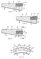
- a modified compensating ring 110 ( Figure 4) likewise fits into a rabbet 92 that opens out of the cup 62 of one of the bearings 30 or 50.
- the ring 110 includes an insert 112 which is formed from a soft elastomer, such as VITON elastomer.
- the ring 110 also includes two bands 114 and 116, each of U-shaped cross-section which telescope with respect to each other and encapsulate the insert 112.
- the bands 114 and 116 are preferably moulded from a relatively rigid polymer, although they may be formed from metal as well.
- the bight portion of the smaller band 116 bears against the end face 96 of the rabbet 92, whereas the bight portion of the larger band 114 is presented beyond the back face 84 of the cup 62.
- the insert 112 possesses a high coefficient of thermal expansion, considerably greater than that of the case 2, and is bonded to neither of the bands 114 nor 116 along its cylindrical surfaces.
- the two bands 114 and 116 are fitted together loosely enough to enable one to slide relative to the other, and the insert expands and contracts in response to temperature variations.
- Still another modified compensating ring 120 ( Figure 5) also fits in the rabbet 92 of the cup 62 for the bearing 30 or 50, but the cup 62 along the end face 96 of its rabbet 92 is further provided with a shallow annular groove 122 that opens out of the cylindrical surface 94 for the rabbet 92.
- the ring 120 includes an insert 124 which is formed from a polymer or elastomer having a high coefficient of thermal expansion.
- the insert 120 for all intents and purposes fills the rabbet 92 and indeed along its inner surface is provided with a nib 126 which projects into the groove 122 to retain the ring 124 in the rabbet 92.
- the compensating ring 120 includes a backing element 128 of U-shaped configuration.
- One end of the insert 124 fits into the element 128 where it is bonded to the element 128.
- the bight portion of the element 128 lies beyond the back face 84 of the cup 62.
- the element 128 may be moulded from a relatively rigid polymer or stamped from a metal such as steel.
- Still another modified compensating ring 130 fits into an annular recess or groove 132 that is set inwardly from the outwardly presented surface 80 of the cup 62, so that it opens out of the back face 84 between the tapered raceway 82 and the outwardly presented surface 80.
- the ring 130 has an insert 134 and an annular backing plate 136 which are similar to their counterparts in the ring 90.
- the plate 136 is presented, at least in part, beyond the back face 84 of the cup 62.
- the insert 134 has a series of axially directed grooves 138 that enable air to escape, as the compensating ring 130 is fitted into the annular groove 132 of the cup 62.
- Yet another modified compensating ring 140 which fits into the rabbet 92 of the cup 62 for one of the bearings 30 or 50 is designed to utilise the volumetric principle of compensation. It includes an insert 142 formed from a flexible material, such as VITON elastomer, and two backing plates 144, one at each end of insert 142. Being confined radially to achieve a volumetric condition, the insert 142 fits snugly over the cylindrical surface 94 of the rabbet 92 and likewise snugly against the surface of the bore 32 or 54 into which the cup 62 containing the rabbet 92 is located. Both of these surfaces are machined to effect a good seal with the two backing plates 144.
- a flexible material such as VITON elastomer
- each backing plate 144 has a rearwardly directed flange 146 which forms a groove into which the end of the insert 142 fits, and indeed the insert 142 is bonded to the backing plates 144 between the two flanges 146 of each.
- the flanges 146 in turn have sealing lips which lie flush with the two cylindrical surfaces of the insert 142.
- the lips on the inner flanges 146 bear against the cylindrical surface 94 of the rabbet 92, whereas the lips of the outer flanges 146 bear against the cylindrical surface of the housing bore 32 or 54 which surrounds the rabbet 92 and compensating ring 140.
- the flanges 146 and their sealing lips prevent the flexible material of the insert 142 from extruding beyond the backing plates 144 in the presence of heavy axial forces.
- the backing plates 144 may be moulded from a relatively firm polymer, and the one presented toward the shoulder 34 or 58 of the case may have a steel reinforcing element 148 embedded in it.
- the housing bore 32 or 54 is enlarged in the region of the large ends of the tapered roller 64 to provide a counterbore 150 ( Figure 9).
- the bearing 30 or 50 which fits into the bore 32 or 54 has a cup 152 which at the large end of its raceway 82 projects through the counterbore 150 and beyond it where it is provided with an outwardly directed flange 154.
- the compensating ring 90 fits between the shoulder at the end of the counterbore 150 and the flange 154 of the cup 152 where it encircles the outwardly presented cylindrical surface 80 of the cup 152.
- the flange 154 may be provided with an integral lip 156 or an attached ring radially and circumferentially to confine the compensating ring 90 to prevent extrusion and thus rely on the volumetric principle of expansion (Figure 10).
- the compensation provided by the compensating ring 90, or for that matter any of the other rings 110,120, 130 or 140, may be utilised in a transaxle B ( Figure 11) which in may respects resembles the in-line transmission A.
- the transaxle B includes a case 160, which is cast from an aluminium alloy, and in addition an input shaft 162, a main shaft 164, and a differential shaft 166, all of which rotate in the case 160 and are formed from steel.
- the input shaft 162 and the main shaft 164 lie parallel to each other and carry gears 168 which mesh in various combinations to change the speed ratio between the shafts 162 and 164.
- the main shaft 164 couples with the differential shaft 166 through more gearing.
- the input shaft 162 rotates on two single row tapered roller bearings 170 and 172 which are set into opposite ends of the case 160 in the direct configuration.
- the main shaft 164 likewise rotates in two single row tapered roller bearings 174 and 176 set into the case 160 in the direct configuration.
- Either one or both of the bearings 170 and 172 for the input shaft 162 may be fitted with the compensating ring 90, or any of the other rings 110, 120, 130 or 140, and the same holds true with regard to bearings 174 and 176 of the countershaft 164.
- either one of the bearings 178 of the differential shaft 166 may have a compensating ring 90, but the lesser spread between those bearings 178 reduces differential shaft expansion and contraction, and for most transaxles B, the ring 90 is not required at the differential shaft bearings 178.
- compensating rings 90, 110, 120, 130 and 140 are shown mounted on a cup, they may also be mounted in a cone ( Figure 12). This invention can also apply to automatic transmissions and transaxles as well.
Landscapes
- Engineering & Computer Science (AREA)
- General Engineering & Computer Science (AREA)
- Mechanical Engineering (AREA)
- Support Of The Bearing (AREA)
- Mounting Of Bearings Or Others (AREA)
Claims (15)
- Un palier à rouleaux coniques (comprenant une première voie de roulement sous la forme d'un cone (60) ayant une voie de roulement conique présentée extérieurement (70) et une face arrière (76) située après l'extrêmité de diamètre supérieur de la voie de roulement; une deuxième voie de roulement sous la forme d'une cuvette (62) située autour du cone et ayant une voie de roulement présentée intérieurement (82) et une face arrière (84) à l'extrêmité de diamètre inférieur de la voie de roulement, des roulements coniques (64) disposés en rangée unique entre les voies de roulement du cone et de la cuvette, et un anneau à compensation (90) servant de butée avec l'une desdites voies de roulement pour le montage axial d'une desdites voies de roulement contre l'autre desdites voies de roulement par l'intermédiaire desdits roulements, ledit anneau étant composé d'un matériau ayant un haut coefficient de dilatation thermique, caractérisé par le fait que ladite voie de roulement (62) a une encoche offrant une surface (94) permettant le logement de l'anneau de manière radiale et une butée ou surface de renfort (96) orientée axialement dans la même direction que la face arrière (84) de ladite voie de roulement, ledit anneau (90) étant disposé dans ladite encoche et contre ladite surface de renfort (96).
- Un palier à rouleaux coniques ainsi revendiqué à la Revendication 1 dans lequel l'anneau de compensation (90) est porté par la cuvette (62).
- Un palier à rouleaux coniques ainsi revendiqué à la Revendication 2 dans lequel l'encoche (92) s'ouvre sur la face arrière (84) de la cuvette.
- Un palier à rouleaux coniques ainsi revendiqué à la Revendication 1 ou à la Revendication 2 dans lequel l'encoche (92) est un rabat sortant de la face arrière (84) et de la surface externe (80) de la cuvette.
- Un palier à rouleaux coniques ainsi revendiqué à la Revendication 2 dans lequel la cuvette (152) a une ailette orientée radialement vers l'extérieur et dans lequel la surface de renfort est sur l'ailette.
- Un palier à rouleaux coniques ainsi revendiqué dans quelqu'une des Revendications 1 à 5 dans lequel l'anneau de compensation (90) a un élément de renfort (100) plus dur que ledit matériau.
- Un palier à roulements coniques ainsi revendiqué à la Revendication 6 dans lequel ledit matériau est un élastomère.
- Une combinaison comprenant un boîtier (2) ayant des faces de butée coaxiales pour le logement des moyens d'arbre, des moyens d'arbre (4,6) dans le boîtier dont les moyens d'arbre ont des faces de butée (26,36) présentées respectivement vers les faces de butée du boîtier et espacées axialement par rapport à ce dernier, les moyens d'arbre étant composés d'un matériau ayant un coefficient de dilatation thermique différent de celui du matériau du boîtier, et au moins deux roulements (20,30) soutenant les moyens d'arbre (4,6) dans le boîtier, les roulements ayant une configuration visant à loger à la fois les charges radiales et axiales, chacun des roulements étant monté dans le boîtier et sur les moyens d'arbre (4,6) entre les faces de butée du boîtier et les moyens d'arbre, les faces de butée étant en opposition l'une à l'autre, en sorte que les roulements confinent les moyens d'arbre à la fois radialement et axialement dans le boîtier, chaque roulement (20,30) ayant des voies internes et externes présentées respectivement face aux faces de butée des moyens d'arbre et du boîtier, chacun des deux roulements (20,30) ayant des voies de roulement disposées mutuellement l'une en face de l'autre et en face des éléments de roulement (64) roulant le long des voies de roulement, et un anneau de compensation (90) disposé axialement entre au moins l'une desdites voies de roulement et la face de butée (34) en face de laquelle ladite voie de roulement est située, pour répondre à des variations de température dans le roulement, permettant par là-même de compenser la dilatation et la contraction thermique différentielle entre l'arbre et le boîtier, caractérisée par le fait que ladite voie a une encoche (92) dans laquelle ledit anneau (90) est radialement situé et une surface de butée (96) contre laquelle l'anneau est disposé, afin de faire butée à la face de butée (34) située face à l'anneau mentionné.
- La combinaison ainsi revendiquée à la Revendication 8 dans laquelle l'anneau de compensation (90) comprend un matériau flexible qui est rigidement confiné par un ergot et de manière radiale dans l'encoche en sorte que le matériau ne puisse se dilater radialement vers l'intérieur ou vers l'extérieur, la contraction ou l'expansion en volume ne se manifestant que dans la direction axiale.
- La combinaison ainsi revendiquée à la Revendication 8 dans laquelle l'anneau de compensation comporte un anneau composé d'un matériau flexible confiné entre deux bandes annulaires (114,116) montées en engagement de téléscopage axial de l'une par rapport à l'autre.
- La combinaison ainsi revendiquée à la Revendication 9 ou à la Revendication 10 dans laquelle ledit matériau flexible est un élastomère de substance incompressible.
- La combinaison ainsi revendiquée dans quelqu'une des Revendications 8 à 11 dans laquelle le roulement est un palier à rouleaux coniques, ladite encoche étant formée sur la face arrière (84) à l'extrémité de petit diamètre de la voie de roulement conique de la voie externe (62) du roulement.
- La combinaison ainsi revendiquée à la Revendication 12 dans laquelle l'encoche (90) est un rabat sortant de la surface cylindrique externe (80) et de la face arrière (84) de ladite voie externe.
- La combinaison ainsi revendiquée à la Revendication 8, dans laquelle l'anneau de compensation comprend une pièce rapportée (112) et la première et la seconde bandes annulaires (114,116) qui ensemble encapsulent substanciellement la pièce rapportée, la pièce rapportée étant composée d'un matériau possèdant un coefficient de dilatation thermique supérieur aux coefficients de dilatation thermique des matériaux composant le boîtier (2) et l'arbre (4,6), les deux bandes annulaires confinant la pièce rapportée de manière radiale mais étant capables de se déplacer axialement l'une par rapport à l'autre lorsque la pièce rapportée se dilate ou se contracte axialement en réaction à des variations de température dans le roulement.
- La combinaison ainsi revendiquée à la Revendication 14, dans laquelle la première bande (116) est installée à l'intérieur de la seconde bande (114) en sorte que les deux bandes se téléscopent l'une dans l'autre lorsque la pièce rapportée (112) se dilate.
Priority Applications (1)
| Application Number | Priority Date | Filing Date | Title |
|---|---|---|---|
| EP95100984A EP0668448B1 (fr) | 1990-03-21 | 1991-02-27 | Machine comportant des paliers à compensation thermique |
Applications Claiming Priority (2)
| Application Number | Priority Date | Filing Date | Title |
|---|---|---|---|
| US07/496,854 US5028152A (en) | 1990-03-21 | 1990-03-21 | Machine with thermally compensated bearings |
| US496854 | 1990-03-21 |
Related Child Applications (2)
| Application Number | Title | Priority Date | Filing Date |
|---|---|---|---|
| EP95100984.4 Division-Into | 1991-02-27 | ||
| EP95100984A Division EP0668448B1 (fr) | 1990-03-21 | 1991-02-27 | Machine comportant des paliers à compensation thermique |
Publications (3)
| Publication Number | Publication Date |
|---|---|
| EP0448239A2 EP0448239A2 (fr) | 1991-09-25 |
| EP0448239A3 EP0448239A3 (en) | 1992-04-15 |
| EP0448239B1 true EP0448239B1 (fr) | 1995-08-09 |
Family
ID=23974461
Family Applications (2)
| Application Number | Title | Priority Date | Filing Date |
|---|---|---|---|
| EP95100984A Expired - Lifetime EP0668448B1 (fr) | 1990-03-21 | 1991-02-27 | Machine comportant des paliers à compensation thermique |
| EP91301618A Revoked EP0448239B1 (fr) | 1990-03-21 | 1991-02-27 | Machine comportant des paliers à compensation thermique |
Family Applications Before (1)
| Application Number | Title | Priority Date | Filing Date |
|---|---|---|---|
| EP95100984A Expired - Lifetime EP0668448B1 (fr) | 1990-03-21 | 1991-02-27 | Machine comportant des paliers à compensation thermique |
Country Status (5)
| Country | Link |
|---|---|
| US (1) | US5028152A (fr) |
| EP (2) | EP0668448B1 (fr) |
| JP (1) | JP2934329B2 (fr) |
| BR (1) | BR9101090A (fr) |
| DE (2) | DE69131756T2 (fr) |
Cited By (1)
| Publication number | Priority date | Publication date | Assignee | Title |
|---|---|---|---|---|
| DE102011008612A1 (de) | 2011-01-14 | 2012-07-19 | GM Global Technology Operations LLC (n. d. Ges. d. Staates Delaware) | Wellenlageranordnung mit thermischer Anpassungsvorrichtung |
Families Citing this family (84)
| Publication number | Priority date | Publication date | Assignee | Title |
|---|---|---|---|---|
| JP2832869B2 (ja) * | 1991-05-10 | 1998-12-09 | 株式会社ゼクセル | 可変容量型べーン型圧縮機の軸受構造 |
| GB9225877D0 (en) * | 1992-12-11 | 1993-02-03 | Lucas Ind Plc | Gearbox |
| SE502460C2 (sv) * | 1993-06-04 | 1995-10-23 | Bofors Ab | Sätt och anordning för temperaturoberoende lagring |
| US5585682A (en) * | 1993-11-10 | 1996-12-17 | Sundstrand Corporation | Thermally compensated assembly for a generator |
| US5562349A (en) * | 1994-11-15 | 1996-10-08 | Honeywell Inc. | Bearing assembly having thermal compensation |
| US5598747A (en) * | 1995-05-04 | 1997-02-04 | Dana Corporation | Thermal compensating bearing support structure for transmission case |
| CA2182923C (fr) * | 1995-08-10 | 2006-10-10 | Walter P. Waskiewicz | Garniture de coussinet/palier |
| FR2759129B1 (fr) * | 1997-01-31 | 1999-03-05 | Roulements Soc Nouvelle | Roulement et palier comportant un insert de compensation thermique |
| US6135641A (en) * | 1997-10-30 | 2000-10-24 | Honeywell International Inc. | Hybrid duplex bearing assembly having thermal compensation |
| DE19833910B4 (de) * | 1998-07-28 | 2007-07-12 | Zf Friedrichshafen Ag | Wärmedehnungsausgleich |
| US6334713B1 (en) | 1999-03-23 | 2002-01-01 | Roller Bearing Industries, Inc. | Bearing assembly having an improved wear ring liner |
| US6250815B1 (en) * | 1999-06-24 | 2001-06-26 | Zf Meritor, Llc | Temperature compensating carrier bearing assembly |
| EP1212556A1 (fr) | 1999-08-16 | 2002-06-12 | Roller Bearing Industries, Inc. | Joint de roulement |
| DE10006001B4 (de) * | 2000-02-11 | 2010-11-25 | Audi Ag | Vorrichtung zum Lagern einer Welle |
| DE10023947A1 (de) * | 2000-05-16 | 2001-11-22 | Bosch Gmbh Robert | Wälzlager, Kolbenpumpe und Pumpenaggregat |
| US6481894B1 (en) | 2001-02-23 | 2002-11-19 | Lord Corporation | Pitch bearing |
| US6939052B1 (en) * | 2003-01-27 | 2005-09-06 | Precision Components, Inc. | Bearing with integrated mounting features |
| FR2853370B1 (fr) * | 2003-04-01 | 2006-05-05 | Roulement muni d'un insert en elastomere et machine agricole comportant un tel roulement | |
| US7219938B2 (en) * | 2003-09-09 | 2007-05-22 | The Timken Company | Backing ring for railcar axle |
| US20060018582A1 (en) * | 2004-07-26 | 2006-01-26 | Mircea Gradu | Bearing having thermal compensating capability |
| US20090080824A1 (en) * | 2004-07-26 | 2009-03-26 | The Timken Company | Bearing having thermal compensating capability |
| US20060104553A1 (en) * | 2004-11-12 | 2006-05-18 | Timken Us Corporation | Radially adjustable linear bearing assembly |
| US7175560B2 (en) * | 2005-01-20 | 2007-02-13 | American Axle & Manufacturing, Inc. | Thermally compensating bearing preload arrangement in axle assembly |
| DE102005043945A1 (de) * | 2005-09-15 | 2007-03-22 | Schaeffler Kg | Radialwälzlager, insbesondere einreihiges Schrägkugellager für das Festlager einer Werkzeugmaschinen-Hauptspindel |
| DE102005043954A1 (de) * | 2005-09-15 | 2007-03-22 | Schaeffler Kg | Radialwälzlager, insbesondere einreihiges Zylinderrollenlager für das Loslager einer Werkzeugmaschinen-Hauptspindel |
| DE102006014790A1 (de) * | 2006-03-29 | 2007-10-11 | Getrag Ford Transmissions Gmbh | Getriebe mit Ausgleichsscheibe |
| US7318759B2 (en) * | 2006-06-07 | 2008-01-15 | Honeywell International, Inc. | Preload system for bearings in a waterjet propulsion apparatus |
| DE602007003359D1 (de) * | 2006-06-30 | 2009-12-31 | Timken Co | Konisches rollenlager mit abnehmbarer rippe |
| EP2085626B1 (fr) * | 2006-11-13 | 2013-08-21 | JTEKT Corporation | Palier à roulement et dispositif de palier à roulement |
| JP2008196570A (ja) * | 2007-02-13 | 2008-08-28 | Jtekt Corp | 転がり軸受装置 |
| US8678665B2 (en) * | 2007-03-08 | 2014-03-25 | Twin Disc., Inc. | Bearing arrangement for heavy duty marine transmission |
| DE102007018928A1 (de) | 2007-04-21 | 2008-10-23 | Schaeffler Kg | Kompensationsvorrichtung |
| DE102007018929A1 (de) | 2007-04-21 | 2008-10-23 | Schaeffler Kg | Vorrichtung zur Kompensation von thermisch bedingten axialen Relativverschiebungen |
| DE102007020521A1 (de) * | 2007-05-02 | 2008-11-06 | Schaeffler Kg | Kompensationsvorrichtung |
| DE102007043474A1 (de) | 2007-09-12 | 2009-03-19 | Schaeffler Kg | Lageranordnung |
| DE102007045252A1 (de) | 2007-09-21 | 2009-04-02 | Schaeffler Kg | Vorrichtung zum Ausgleich axialer Wärmedehnungen einer Wälzlageranordnung |
| DE102007045655A1 (de) | 2007-09-25 | 2009-04-02 | Schaeffler Kg | Vorrichtung zum Ausgleich axialer Wärmedehnungen einer Wälzlageranordnung |
| DE102007050066A1 (de) | 2007-10-19 | 2009-04-23 | Schaeffler Kg | Vorrichtung zur Kompensation von thermisch bedingten axialen Relativverschiebungen |
| DE102007050201A1 (de) | 2007-10-20 | 2009-04-23 | Schaeffler Kg | Kompensationsvorrichtung zum Ausgleich thermisch bedingter relativer axialer Lageänderungen zwischen zwei Bauteilen |
| US8036863B2 (en) * | 2008-02-07 | 2011-10-11 | American Axle & Manufacturing, Inc. | Method for customizing a bearing bore |
| JP2009203846A (ja) * | 2008-02-27 | 2009-09-10 | Jtekt Corp | ターボチャージャ用軸受装置 |
| AU2009308429B2 (en) * | 2008-10-24 | 2014-08-28 | Twin Disc, Inc. | Bearing arrangement for heavy duty marine transmission |
| DE102008061042A1 (de) | 2008-12-09 | 2010-06-17 | Schaeffler Kg | Wärmedehnungsausgleichselement sowie Wälzlager |
| DE102009056615A1 (de) | 2009-12-02 | 2011-06-09 | Schaeffler Technologies Gmbh & Co. Kg | Ausgleichselement in einem Wälzlager, Lageranordnung und Getriebe |
| GB2478523A (en) * | 2010-03-05 | 2011-09-14 | Gm Global Tech Operations Inc | Housing assembly arrangement |
| DE102010011444A1 (de) | 2010-03-15 | 2011-09-15 | Schaeffler Technologies Gmbh & Co. Kg | Thermokompensationselement und Lageranordnung mit einem Thermokompensationselement |
| DE102010035062A1 (de) * | 2010-08-21 | 2012-02-23 | Schaeffler Technologies Gmbh & Co. Kg | Kegelrollenlager mit Käfig |
| DE102010035784A1 (de) | 2010-08-30 | 2012-03-01 | Schaeffler Technologies Gmbh & Co. Kg | Mehrring-Wälzlager zur Axiallagerung einer Welle |
| DE102010048728A1 (de) | 2010-10-16 | 2012-04-19 | Schaeffler Technologies Gmbh & Co. Kg | Lagerring sowie Lageranordnung mit einem Lager |
| US8591120B2 (en) | 2010-10-27 | 2013-11-26 | Schaeffler Technologies AG & Co. KG | Rolling bearing |
| US8684608B2 (en) | 2010-10-27 | 2014-04-01 | Schaeffler Technologies AG & Co. KG | Rolling bearing |
| US8690445B2 (en) | 2010-10-27 | 2014-04-08 | Schaeffler Technologies AG & Co. KG | Rolling bearing arrangement |
| DE102011087080A1 (de) | 2011-01-28 | 2012-08-02 | Schaeffler Technologies Gmbh & Co. Kg | Thermoausgleichselement mit wellenförmiger Feder |
| DE102011004414A1 (de) | 2011-02-18 | 2012-08-23 | Schaeffler Technologies Gmbh & Co. Kg | Verfahren zur Montage von wenigstens einem Thermokompensationselement in vorgespannten Lageranordnungen |
| DE102011006747A1 (de) | 2011-04-05 | 2012-10-11 | Schaeffler Technologies Gmbh & Co. Kg | Kegelrollenlager |
| US8408807B2 (en) | 2011-04-19 | 2013-04-02 | Schaeffler Technologies AG & Co. KG | Hydraulic thermal compensation for bearing systems |
| US9222508B2 (en) | 2011-05-17 | 2015-12-29 | Schaeffler Technologies AG & Co. KG | Bearing race with integrated spring |
| FR2978219B1 (fr) * | 2011-07-22 | 2014-05-16 | Ntn Snr Roulements | Montage d’un arbre tournant dans un carter par l’intermediaire d’un roulement |
| DE102012202900A1 (de) * | 2012-02-27 | 2013-08-29 | Aktiebolaget Skf | Lageranordnung |
| DE102012006390A1 (de) | 2012-03-30 | 2013-10-02 | Johann Singer | Vorrichtung zum Einstellen und Aufrechterhalten einer optimalen Wälzlagervorspannkraft |
| FR2991411A1 (fr) * | 2012-05-31 | 2013-12-06 | Skf Ab | Dispositif de palier a roulement pour colonne de direction. |
| US20160061254A1 (en) * | 2013-03-28 | 2016-03-03 | Aktiebolaget Skf | Bearing assembly and method for assembling and mounting said bearing assembly with a component supporting said bearing assembly |
| CN105074247A (zh) * | 2013-03-28 | 2015-11-18 | 斯凯孚公司 | 轴承组件及组装和安装轴承组件与支撑轴承组件的部件的方法 |
| DE102014204101A1 (de) * | 2013-04-23 | 2014-10-23 | Schaeffler Technologies AG & Co. KG | Kompakte, integrierte Vorspannvorrichtung für Lager |
| EP2840271A3 (fr) * | 2013-08-22 | 2015-05-06 | Schaeffler Technologies AG & Co. KG | Arrangement de palier avec une bague de retenue et méthode de fabrication |
| DE102013220222A1 (de) | 2013-10-08 | 2015-04-09 | Schaeffler Technologies AG & Co. KG | Lagervorrichtung |
| DE102013221601B4 (de) * | 2013-10-24 | 2015-11-19 | Aktiebolaget Skf | Außenring für ein Wälzlager sowie Verfahren zur Montage eines Wälzlagers |
| DE102013222840A1 (de) | 2013-11-11 | 2015-05-13 | Schaeffler Technologies Gmbh & Co. Kg | Sicherungsbauteil zur Axial- und Verdrehsicherung eines Wälzlagerrings |
| DE102013223173B4 (de) * | 2013-11-14 | 2015-10-29 | Aktiebolaget Skf | Lageranordnung |
| DE102014207922A1 (de) | 2014-04-28 | 2015-10-29 | Aktiebolaget Skf | Lagerring mit einem Temperaturkompensationsring, Lager mit dem Lagerring sowie Verfahren zum Herstellen eines Lagerrings |
| DE102014210908A1 (de) * | 2014-06-06 | 2015-12-17 | Aktiebolaget Skf | Lagerring für ein Lager sowie ein Lager mit dem Lagerring und ein Verfahren zum Herstellen eines Lagerrings |
| DE102014219705B4 (de) | 2014-09-29 | 2023-04-27 | Aktiebolaget Skf | Lagerring |
| DE102014219730A1 (de) | 2014-09-29 | 2016-03-31 | Aktiebolaget Skf | Lageranordnung |
| DE102014225029B4 (de) * | 2014-12-05 | 2025-06-05 | Aktiebolaget Skf | Temperaturkompensationsring, Lagerring sowie Lageranordnung |
| DE102015215303B4 (de) | 2015-08-11 | 2022-09-08 | Aktiebolaget Skf | Temperaturkompensationsring sowie Lagerring mit dem Temperaturkompensationsring |
| DE102016115515A1 (de) * | 2016-08-22 | 2018-02-22 | Dt Swiss Ag | Nabe und Nabenserie |
| DE102016224395A1 (de) * | 2016-12-07 | 2018-06-07 | Aktiebolaget Skf | Lageranordnung |
| US20190016004A1 (en) * | 2017-07-17 | 2019-01-17 | Elsner Engineering Works, Inc. | Thermal compensating mount for a knife roll in a web processing machine |
| US10662998B2 (en) | 2018-08-13 | 2020-05-26 | Schaeffler Technologies AG & Co, KG | Sleeve for deep groove ball bearing |
| US10612595B2 (en) | 2018-08-13 | 2020-04-07 | Schaeffler Technologies AG & Co. KG | Lubrication groove for deep groove ball bearing |
| US10612596B1 (en) | 2018-09-24 | 2020-04-07 | Schaeffler Technologies AG & Co. KG | Anti-creep deep groove ball bearing |
| GB2588434B (en) * | 2019-10-24 | 2022-08-10 | Edwards Ltd | Bearing support and pump |
| CN110873123A (zh) * | 2019-11-25 | 2020-03-10 | 苏州溪能环保科技有限公司 | 一种耐久型精密轴承 |
| US11391324B1 (en) | 2021-04-07 | 2022-07-19 | Schaeffler Technologies AG & Co. KG | Creep mitigation design for bearing assembly |
Family Cites Families (26)
| Publication number | Priority date | Publication date | Assignee | Title |
|---|---|---|---|---|
| DE1068516B (fr) * | 1959-11-05 | |||
| DE1066388B (fr) * | 1900-01-01 | |||
| US1867582A (en) * | 1928-09-04 | 1932-07-19 | John Deere Tractor Co | Internal combustion engine |
| US1746978A (en) * | 1928-11-17 | 1930-02-11 | Carl J Winkler | Adapter for bearings |
| US2141145A (en) * | 1938-02-21 | 1938-12-20 | Timken Roller Bearing Co | Cushioned roller bearing and mounting |
| US2324676A (en) * | 1941-06-06 | 1943-07-20 | Chrysler Corp | Bearing |
| US2711356A (en) * | 1952-06-30 | 1955-06-21 | Willis B Ensinger | Bearing construction for high speed rotors |
| US2803507A (en) * | 1952-12-03 | 1957-08-20 | Licentia Gmbh | Resilient spacer rings for multiple bearings rotatably supporting shafts |
| US2700581A (en) * | 1953-03-13 | 1955-01-25 | Aluminium Francais I | Precision fit for bearings and the like |
| US2727796A (en) * | 1955-01-11 | 1955-12-20 | G M Giannini & Co Inc | Temperature compensation of shaft end play and the like |
| US2859033A (en) * | 1956-06-27 | 1958-11-04 | Hughes Aircraft Co | Constant force applying mechanism |
| US2836473A (en) * | 1957-07-26 | 1958-05-27 | Clarence W Tydeman | Mounting for preloading tapered roller bearings |
| US3106432A (en) * | 1961-10-17 | 1963-10-08 | Kearney & Trecker Corp | Adjustable journal bearing with automatic heat compensator |
| US3202466A (en) * | 1963-09-09 | 1965-08-24 | Ford Motor Co | Mounting arrangement with selfcompensating roller bearings |
| US3317258A (en) * | 1964-10-06 | 1967-05-02 | Leblond Mach Tool Co R K | Compensation for spindle creep due to bearing temperature |
| DE1964995U (de) * | 1967-05-20 | 1967-07-27 | Boelkow Gmbh | Nachstellbares lager. |
| SE334781B (fr) * | 1967-12-07 | 1971-05-03 | Skf Svenska Kullagerfab Ab | |
| US3640591A (en) * | 1970-03-04 | 1972-02-08 | Us Air Force | Rolling contact bearing having temperature compensation |
| US3692372A (en) * | 1971-06-24 | 1972-09-19 | Gen Electric | Thermally expansible bearing assembly |
| DE2532370A1 (de) * | 1975-07-19 | 1977-01-20 | Ford Werke Ag | Verfahren zur genauen einstellung von kegelrollenlagern |
| DE2658791C2 (de) * | 1976-12-24 | 1983-02-10 | Planetroll Antriebe Gmbh, 7932 Munderkingen | Stufenlos einstellbares Reibungsgetriebe |
| US4283096A (en) * | 1978-04-21 | 1981-08-11 | United Technologies Corporation | Intershaft bearing |
| GB2080443B (en) * | 1980-07-18 | 1984-09-12 | Lamb Co F Jos | Bearing assembly for machine tool spindles |
| DE3239305A1 (de) * | 1982-10-23 | 1984-04-26 | Zahnradfabrik Friedrichshafen Ag, 7990 Friedrichshafen | Axiallagerabstuetzung |
| US4626111A (en) * | 1985-07-25 | 1986-12-02 | Farrel Corporation | Self-compensating anti-friction bearing clearance device |
| JP2586503B2 (ja) * | 1987-08-17 | 1997-03-05 | 日本精工株式会社 | 軸受の取付装置 |
-
1990
- 1990-03-21 US US07/496,854 patent/US5028152A/en not_active Expired - Lifetime
-
1991
- 1991-02-27 EP EP95100984A patent/EP0668448B1/fr not_active Expired - Lifetime
- 1991-02-27 DE DE69131756T patent/DE69131756T2/de not_active Expired - Fee Related
- 1991-02-27 EP EP91301618A patent/EP0448239B1/fr not_active Revoked
- 1991-02-27 DE DE69111862T patent/DE69111862D1/de not_active Expired - Lifetime
- 1991-03-20 BR BR919101090A patent/BR9101090A/pt not_active IP Right Cessation
- 1991-03-20 JP JP3057236A patent/JP2934329B2/ja not_active Expired - Lifetime
Cited By (1)
| Publication number | Priority date | Publication date | Assignee | Title |
|---|---|---|---|---|
| DE102011008612A1 (de) | 2011-01-14 | 2012-07-19 | GM Global Technology Operations LLC (n. d. Ges. d. Staates Delaware) | Wellenlageranordnung mit thermischer Anpassungsvorrichtung |
Also Published As
| Publication number | Publication date |
|---|---|
| US5028152A (en) | 1991-07-02 |
| JPH0599223A (ja) | 1993-04-20 |
| DE69111862D1 (de) | 1995-09-14 |
| DE69131756T2 (de) | 2000-03-09 |
| EP0668448B1 (fr) | 1999-10-27 |
| BR9101090A (pt) | 1991-11-05 |
| EP0668448A1 (fr) | 1995-08-23 |
| EP0448239A3 (en) | 1992-04-15 |
| DE69131756D1 (de) | 1999-12-02 |
| JP2934329B2 (ja) | 1999-08-16 |
| EP0448239A2 (fr) | 1991-09-25 |
Similar Documents
| Publication | Publication Date | Title |
|---|---|---|
| EP0668448B1 (fr) | Machine comportant des paliers à compensation thermique | |
| US20090080824A1 (en) | Bearing having thermal compensating capability | |
| EP0454324B1 (fr) | Dispositif amortisseur pour palier conique | |
| US6250815B1 (en) | Temperature compensating carrier bearing assembly | |
| US6227713B1 (en) | Tapered roller bearing for working rolls of roll strands | |
| EP0683329B1 (fr) | Palier | |
| EP1548305B1 (fr) | Ensemble de palier à éléments roulants | |
| US20030155803A1 (en) | Wheel-driving axle unit | |
| US4027932A (en) | Clutch release bearing | |
| US20060018582A1 (en) | Bearing having thermal compensating capability | |
| US8602193B2 (en) | Bearing arrangement for heavy duty transmission | |
| CA1244074A (fr) | Roulement de dilatation a double rangee de rouleaux cylindriques | |
| EP1693581B1 (fr) | Dispositif de palier pour arbre de pignon | |
| US6776531B2 (en) | Rolling bearing with seal plate | |
| US7503699B2 (en) | Wheel axle bearing unit | |
| JP5062045B2 (ja) | スラストころ軸受 | |
| US20050064979A1 (en) | Bevel gear transmission | |
| JP3460162B2 (ja) | トランスミッションのシャフト支持構造 | |
| JP2003148596A (ja) | 変速機の軸受装置 | |
| JP2002327761A (ja) | 密封板付転がり軸受とこの密封板付転がり軸受を組み込んだトランスミッション | |
| JP5081571B2 (ja) | シェル形針状ころ軸受 | |
| JP2007333011A (ja) | 深溝玉軸受 | |
| JP2007100791A (ja) | 円すいころ軸受及び軸受装置 | |
| JP2006194292A (ja) | スラストころ軸受 | |
| Dickerhoff et al. | Thermal compensating tapered roller bearing for enhancement of transmission and transaxle performance |
Legal Events
| Date | Code | Title | Description |
|---|---|---|---|
| PUAI | Public reference made under article 153(3) epc to a published international application that has entered the european phase |
Free format text: ORIGINAL CODE: 0009012 |
|
| AK | Designated contracting states |
Kind code of ref document: A2 Designated state(s): DE FR GB SE |
|
| PUAL | Search report despatched |
Free format text: ORIGINAL CODE: 0009013 |
|
| AK | Designated contracting states |
Kind code of ref document: A3 Designated state(s): DE FR GB SE |
|
| 17P | Request for examination filed |
Effective date: 19920617 |
|
| 17Q | First examination report despatched |
Effective date: 19931214 |
|
| GRAA | (expected) grant |
Free format text: ORIGINAL CODE: 0009210 |
|
| AK | Designated contracting states |
Kind code of ref document: B1 Designated state(s): DE FR GB SE |
|
| PG25 | Lapsed in a contracting state [announced via postgrant information from national office to epo] |
Ref country code: FR Free format text: LAPSE BECAUSE OF NON-PAYMENT OF DUE FEES Effective date: 19950809 |
|
| XX | Miscellaneous (additional remarks) |
Free format text: TEILANMELDUNG 95100984.4 EINGEREICHT AM 27/02/91. |
|
| REF | Corresponds to: |
Ref document number: 69111862 Country of ref document: DE Date of ref document: 19950914 |
|
| PG25 | Lapsed in a contracting state [announced via postgrant information from national office to epo] |
Ref country code: SE Effective date: 19951109 |
|
| PG25 | Lapsed in a contracting state [announced via postgrant information from national office to epo] |
Ref country code: DE Effective date: 19951110 |
|
| EN | Fr: translation not filed | ||
| PGFP | Annual fee paid to national office [announced via postgrant information from national office to epo] |
Ref country code: SE Payment date: 19960117 Year of fee payment: 6 |
|
| PGFP | Annual fee paid to national office [announced via postgrant information from national office to epo] |
Ref country code: GB Payment date: 19960119 Year of fee payment: 6 |
|
| PGFP | Annual fee paid to national office [announced via postgrant information from national office to epo] |
Ref country code: FR Payment date: 19960201 Year of fee payment: 6 |
|
| PLBI | Opposition filed |
Free format text: ORIGINAL CODE: 0009260 |
|
| PLBF | Reply of patent proprietor to notice(s) of opposition |
Free format text: ORIGINAL CODE: EPIDOS OBSO |
|
| 26 | Opposition filed |
Opponent name: SKF GMBH Effective date: 19960426 |
|
| PLBF | Reply of patent proprietor to notice(s) of opposition |
Free format text: ORIGINAL CODE: EPIDOS OBSO |
|
| PLBF | Reply of patent proprietor to notice(s) of opposition |
Free format text: ORIGINAL CODE: EPIDOS OBSO |
|
| RDAH | Patent revoked |
Free format text: ORIGINAL CODE: EPIDOS REVO |
|
| RDAG | Patent revoked |
Free format text: ORIGINAL CODE: 0009271 |
|
| STAA | Information on the status of an ep patent application or granted ep patent |
Free format text: STATUS: PATENT REVOKED |
|
| GBPR | Gb: patent revoked under art. 102 of the ep convention designating the uk as contracting state |
Free format text: 961222 |
|
| 27W | Patent revoked |
Effective date: 19961222 |